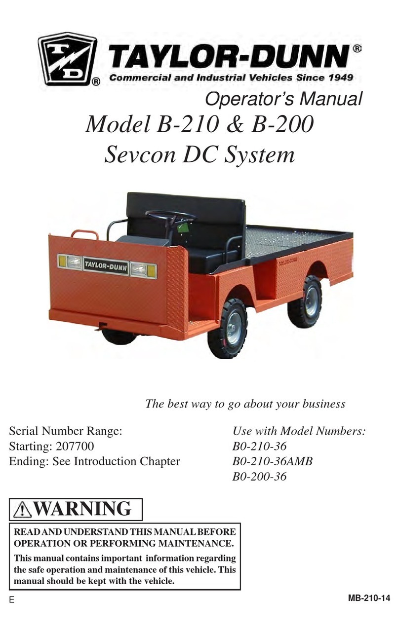
Taylor-Dunn E-451 Building instructions

The Best Way
To Go
About Your
Business
TAYLOR-DUNN
®
READ THEOPERATOR’S MANUALBEFORE OPERATING
THIS VEHICLE.
Theoperator’smanualcontainsimportant information
regarding the safe operation of this vehicle.
WARNING
Starting Serial Number: 206900
Ending Serial Number: See Introduction Chapter
Service and Replacement
Parts Manual
MANUAL: ME-45X-01
E-451 & E-457
Model Numbers:
E0-034-51
E0-034-57
C

Yoursatisfactionisout#1goal.Ifyouhavequestionsorconcerns
with your vehicle, please contact your sales Representative or
Service Advisor at your local dealership.
Taylor-Dunn has a worldwide dealer and distribution network to
provide replacement parts and service for our vehicles.
Referto our website, www.taylor-dunn.com,for a dealerlookup
application.
Originally Published [date]
Revision C, 7/12/2018, contents subject to change without notice
Taylor-Dunn®Mfg.
2114 W. Ball Rd.
Anaheim, CA 92804
(800)-688-8680
(714) 956-4040
(FAX) (714) 956-0504
Visit our Web site: www.taylor-dunn.com
My Vehicle information
Serial Number: .
Date Purchased: .
Date Delivered: .
Dealer Purchased From: .
Salesman Name: .

Taylor-Dunn Contact information
Service, Parts, Sales:
Taylor-Dunn has a network of dealers distributed around the globe to support
our vehicles. Information regarding vehicle sales, replacement parts, or service
should be obtained through your local dealer. A dealer locator can be found on
the Taylor-Dunn website at www.taylor-dunn.com.
If you do not have access to the internet, you can call the factory direct at:
01 (714) 956-4040
Feedback regarding this or any Taylor-Dunn vehicle manual can be sent to:
Taylor-Dunn Manufacturing
Attn: Tech Writer
2114 West Ball Road
Anaheim, CA 92804

The Taylor-Dunn Corporation:
Leading Provider of Commercial & Industrial Vehicles since 1949
Taylor-Dunn Manufacturing:
From the day we shipped our rst vehicle in 1949, we have pursued a singular goal: to build tough, rugged, dependable vehicles to help
our customers move personnel, equipment, and materials. It’s that simple. For over sixty years, our standard and custom vehicles - Burden
Carriers, Personnel Carriers, Stock Chasers, Electric Carts, Tow Tractors & more - have been the leading solution for customers in a
broad range of industrial, commercial, and ground-support markets.
Decades of experience are an invaluable asset, and it is an asset we cherish and protect. Our guiding principle is to provide application-
specic solutions, which are reliable, efcient, and economical.
Our domestic and international network of quality Taylor-Dunn Dealers and Parts & Service Support keeps our customers moving.
Tiger Tractor:
Tiger manufacturing has become a leading manufacturer of internal combustion industrial tractors and ground support equipment. With
tractor capacities ranging from 3,000 - 12,000 pounds drawbar pull, they are ideal for industrial applications as well as aircraft ground
support. As with all Taylor-Dunn vehicles; quality, service, support and reliability are built into all Tiger Tractor products.
Shown below is just a small sample of what Taylor-Dunn has to offer to keep your business moving:

Master Table of Contents
Introduction......................................................7
Service/Maintenance Guidelines....................13
Preventative Maintenance ..............................17
Special Tool List ..............................................21
Lubrication.......................................................25
Front Axle.........................................................29
Drive Axle.........................................................33
Steering............................................................45
Brakes...............................................................51
Drive Motor.......................................................57
Motor Controller ..............................................65
Wire Diagram ...................................................69
Batteries...........................................................73
Tires & Wheels.................................................79
Hardware Information .....................................83
Replacement Parts..........................................89
Note: Eachsectiontitlepagecontains
a section table of contents


Table of Contents
Introduction
This section is one section of a complete service
manual. Before starting any procedure, read all
warnings and instructions that are located in the
Service Guidelines chapter.
WARNING
Introduction
About this manual...........................................8
Who Should Read This Manual......................8
How To Use This Manual ................................8
Conventions ............................................................9
Signal Words and Their Denitions: ........................9
Responsibilities...............................................10
How to Identify Your Vehicle ..........................11
Web Site Registration .....................................11

Page-8 ME-45X-01
Introduction E-451 & E-457
ABOUT THIS MANUAL
The purchase of this vehicle shows a belief in
high quality products manufactured in the USA.
Taylor-Dunn®, a leading manufacturer of electric burden
and personnel carriers since 1949, wants to be sure
this vehicle provides years of reliable service. Please
continue to read this manual and enjoy this high quality
Taylor-Dunn®vehicle.
This manual is to serve as a guide for the service,
repair, and operation of Taylor-Dunn®vehicles and is
notintended as a trainingguide.Taylor-Dunn®hasmade
every effort to include as much information as possible
about the operation and maintenance of this vehicle.
Taylor-Dunn is not to be held liable for errors in this
manual or any consequential damage that results from
the use of this manual.
Before servicing, operating, training or performing
maintenance on this or any other Taylor-Dunn®vehicle,
read the appropriate Taylor-Dunn®manual.
Each Taylor-Dunn®manual references the applicable
models and serial numbers on the front cover.
Please, be aware of all cautions, warnings, instructions,
and notes contained in this manual.
WHO SHOULD READ THIS MANUAL
This manual is intended for use by anyone who is going
to operate, own, perform maintenance on, service, or
order parts for this Taylor-Dunn®vehicle. Each person
shall be familiar with the parts of this manual that apply
to their use of this vehicle.
HOW TO USE THIS MANUAL
This manual is organized into these main sections:
Introduction
This section describes how to use this service manual
and how to identify your vehicle.
Maintenance, Service, and Repair
This section gives specic information on the servicing
of the vehicle and a schedule for maintenance checks.
This manual is for mechanical repairs only and does
not include electrical diagnosis procedures. Electrical
diagnosisproceduresareincluded in a separate manual.
Replacement Parts
This section provides an illustrated view of various
assemblies.Theillustrationsare accompanied bytables
identifying the parts.

Page-9
ME-45X-01
Introduction
E-451 & E-457
Conventions
Symbols and/or words used to dene Dangers, Warnings, Cautions, and Notices are found throughout this manual.
The “Words” in this context will be referred to as “Signal words.” The words dened here as “signal words” may be
used elsewhere in the text of this document without being a signal word. When used as a signal word, the signal
word will be enclosed in a solid rectangle with white background (example below).
Signal Words and Their Denitions:
DANGER: This signal word will be accompanied by the safety alert symbol (see below). “DANGER” will indicate
a hazard that, if not avoided, WILL result in death or serious bodily injury to yourself, the operator or
passengers of the vehicle, or people in the immediate area of the vehicle.
WARNING: This signal word will be accompanied by the safety alert symbol (see below). “WARNING” will indicate
a hazard that, if not avoided, may result in death or serious bodily injury to yourself, the operator or
passengers of the vehicle, or people in the immediate area of the vehicle.
CAUTION: This signal word will be accompanied by the safety alert symbol (see below). “CAUTION” will indicate a
hazardthat,if not avoided, mayresultinminoror moderate injury toyourself,theoperator or passengers
of the vehicle, or people in the immediate area of the vehicle.
NOTICE: This signal word will not be accompanied by the safety alert symbol. “NOTICE” will indicate a condition
that if not avoided may result in property damage. “Property” is dened as the vehicle, components in
the vehicle and/or the surrounding area such as buildings, other vehicles, etc.
Safety alert symbol (see
above).
Represents a high voltage
hazard.
Represents an explosion
hazard.
Represents a corrosive
chemical hazard.
Represents a re hazard.
Represents a poisonous
chemical hazard.
Some of the decals applied to the
vehiclewillhave iconsrepresenting their
function. The icons and their denitions
are listed below:
Read the operators manual.
Read the maintenance manual.
Keep arms and legs inside the
vehicle.
Parking brake ON.
Parking brake OFF.
Do not get wet.
Do not spray wash.
This is an example of a safety alert message. This
message will contain information about a hazard and/
or instructions on avoiding a hazard. The actual size
and location of this warning box may vary.
WARNING
Safety Messages
Importantinformationnotifying you of any conditionsthat
may result in hazards to yourself, persons nearby, and/
or hazards to the vehicle will be presented in a text box
with a black border and may include a signal word (see
above). To the right is an example of a safety message.
The safety message may include additional warning
icons representing the type of hazard. The following
is a list of these icons and what they represent. These
icons may also be included on the various warning and
information decals applied to the vehicle.

Page-10 ME-45X-01
Introduction E-451 & E-457
RESPONSIBILITIES
Of the Owner...
The owner of this or any Taylor-Dunn vehicle is
responsible for the overall maintenance and repairs
of the vehicle, as well as the training of operators.
Theownerisalso responsible for operator trainingper
the following federal regulations:
• ANSI/ITSDF 56.8-2006 Personnel and Burden
Carriers: Part II, Paragraph 6.2a.
• ANSI/ITSDF 56.9 – 2007 Safety Standard for
Operator Controlled Industrial Tow Tractors: Part
II, paragraph 4.11.
• Code of Federal Regulations (CFR) Title 29,
Subtitle B, Chapter Xvii OSHA, Part 1910.178
Powered Industrial Trucks (2011): 1910.178,
Section (l).
Per OSHA Regulation, 29 CFR 1910.178 Powered
Industrial Truck Operator Training, the owner must
keepa record ofconducted training andmaintenance
performed on the vehicle.
Of the Service Personnel...
The service personnel are responsible for the service
and maintenance of the vehicle. At no time shall a
service person allow any untrained personnel to service
or repair this or any Taylor-Dunn®vehicle. For the
purposes of training, a qualied service person may
oversee the repairs or services being made to a vehicle
by an individual in training.At no time shall an untrained
individualbeallowedtoserviceorrepairavehiclewithout
supervision. This manual is not a training guide.
Personnel performing service and repair shall have
knowledge of:
• Basic standard automotive repair procedures
• Basic DC electrical theory
• DC series wound motor speed control operation
• Use of digital and analog multi-meters
• Lead acid batteries
Personnel performing maintenance shall have basic
knowledge of standard automotive maintenance
procedures and lead acid batteries.
Of the Operator...
A vehicle shall not be operated until the operator has
successfully completed an operator training course
provided by the owner of the vehicle.
Theoperator is responsibleto be surethat the vehicle
is operated only on authorized roads, highways, and
installations.
The operator is responsible to confirm that all
passengers are properly seated and properly using
the available restraints.
The operator is responsible for the safe operation of
the vehicle, preoperational and operational checks
on the vehicle, and the reporting of any problems to
service and repair personnel.
To maintain peak performance, always use original
Taylor-Dunn replacement parts intended for use
on your vehicle. Taylor-Dunn components are
designed and tested for use on specic Taylor-Dunn
model vehicles. Only use the correct Taylor-Dunn
replacement components for your Taylor-Dunn
vehicle.
Do not modify your vehicle:
Modications to this vehicle may have an undesirable
affect on the operation of the vehicle, result in
additional frame stress, or stress other components
resulting in premature failure or an unsafe condition
and may lead to an accident resulting in serious injury
or death.
WARNING
The only personnel authorized to repair, modify, or
adjust any part of this or any Taylor-Dunn vehicle is
a factory authorized service technician. Repairs made
by unauthorized personnel may result in damage to
the vehicles systems which could lead to an unsafe
condition resulting in severe bodily injury and/or
property damage. Unauthorized repairs may also
void the vehicles warranty.
WARNING

Page-11
ME-45X-01
Introduction
E-451 & E-457
HOW TO IDENTIFY YOUR VEHICLE
This manual is valid only for the serial numbers listed on the front cover. If the ending serial number is blank, then
this manual was for current production vehicles when printed. If you did not receive this manual with the vehicle,
you should conrm this manual is valid for your serial number at the Taylor-Dunn web site.
The locations of the model and serial numbers are shown in the illustrations below:
WEB SITE REGISTRATION
Registering on the Taylor-Dunn web site will give you access to a wealth of information about your vehicle and the
entire Taylor- Dunn line of vehicles. Your contact information will remain condential and will not be shared outside
of the Taylor-Dunn corporation.
Once registered on the Taylor-Dunn web site, you will have access to:
• Additional Taylor-Dunn product information.
• Worldwide Taylor-Dunn dealer contacts
• Vehicle Service, Maintenance, Operator, Troubleshooting, and Parts manuals.
• Replacement part number lookup utility
www.taylor-dunn.com

Page-12 ME-45X-01
Introduction E-451 & E-457
Notes:

Table of Contents
Service/Maintenance
Guidelines
Service/Maintenance Guidelines
READ ME FIRST-Maintenance Guidelines and
General instructions.................................14
Vehicle Modications......................................15
Replacement Parts..........................................16
Using Non-OEM Replacement Components...........16

Service/Maintenance Guidelines
Page 14
E-451 & E-457
ME-45X-01
READ ME FIRST-MAINTENANCE GUIDELINES AND GENERAL
INSTRUCTIONS
• Read the operator’s manual before operating this vehicle.
• Avoid re hazards and have re protection equipment present in the work area.
• Conduct vehicle performance checks in an authorized area where safe clearance exists.
• Ventilate the work area properly.
• Regularly inspect and maintain the following systems in a safe working condition: brakes, steering
mechanisms, speed and directional control mechanisms, warning devices, lights, governors, guards, and
safety devices.
• Inspect and maintain battery limit switches, protective devices, electrical conductors, and connections in
conformance with Taylor-Dunn’s®recommended procedures.
• Keep the vehicle in clean condition to minimize re hazards and facilitate detection of loose or defective parts.
• Do not use an open ame to check level or leakage of battery electrolyte.
• Do not use open pans of fuel or ammable uids for cleaning parts.
• Only properly trained and authorized technicians should perform maintenance or repairs to this vehicle.
When lifting the vehicle, always use a hoist with
lifting strap, or a jack of adequate capacity. Use jack
stands to support the vehicle before starting any
repairs. Failure to use lifting and support devices of
rated load capacity may result in severe bodily injury.
WARNING
On a three wheel vehicle: When raising both
rear wheels, the front end of the vehicle must be
supported to prevent tipping. The rear of the vehicle
should be raised by a means so that the left and right
side are raised equally, such as a hoist with xed
length chains attached to the left and right side of
the vehicle. Failure to properly support the vehicle
may result in the vehicle tipping over causing severe
bodily injury and/or property damage.
WARNING
The vehicle may operate at any time while performing
control system test procedures.
All tests must be performed with the drive wheels
off of the ground and the vehicle supported with
jack stands.
Testing with drive wheels on the ground may result in
vehicle movement causing severe bodily injury and/
or property damage.
WARNING
The only personnel authorized to repair, modify, or
adjust any part of this or any Taylor-Dunn vehicle is
a factory authorized service technician. Repairs made
by unauthorized personnel may result in damage to
or improper operation of the vehicles systems which
could lead to an unsafe condition resulting in severe
bodily injury and/or property damage.
Unauthorized repairs may also void the vehicles
warranty.
WARNING
Read and follow all of the guidelines listed below.
Failure to follow these guidelines may result in severe
bodily injury and/or property damage.
WARNING
Periodic maintenance and service must be performed
on this vehicle. Failure to complete these scheduled
maintenance and service procedures can result in
severe bodily injury and/or property damage. It is
the owner and/or operators responsibility to ensure
that proper service and maintenance is performed on
the vehicle, described in this manual.
WARNING
BEFORE STARTING ANY REPAIRS
1) Make sure the Start switch is in the “OFF” position,
then remove the key.
2) Place the Direction Control switch in the center
“OFF” position.
3) Set the park brake or conrm the brake is set when
equipped with an automatic brake.
4) Place blocks under the front or rear wheels to
prevent vehicle movement.
5) Disconnect the main positive and negative cables
at the batteries.
WARNING

Service/Maintenance Guidelines
Page 15
ME-45X-01
E-451 & E-457
VEHICLE MODIFICATIONS
Taylor-Dunn vehicles are designedandmanufactured in accordancewithANSI/ITSDFandOSHAregulations.
Per ANSI/ITSDF and OHSA, modications to the vehicle must be approved by the manufacturer. Listed below
are the specic regulations:
ANSI/ITSDF 56.8-2006 Personnel and Burden Carriers
Paragraph 8.2q:
Modications and additions which affect capacity and safe machine operation shall not be performed by
the customer or user without manufacture’s prior written authorization; where authorized modications
have been made, the user shall ensure that capacity, operation, warning, and maintenance instructions
plates, tags, or decals are changed accordingly.
Paragraph 8.2r:
Care shall be taken to ensure that all replacement parts are interchangeable with the original parts and
of a quality at least equal to that provided in the original equipment.
ANSI/ITSDF 56.9 – 2007 Safety Standard for Operator Controlled Industrial Tow
Tractors
Paragraph 6.2.14:
Modications and additions which affect capacity and safe tow tractor operation shall not be performed
without manufacture’s prior written approval. Capacity, operation, and maintenance instructions plates,
tags, or decals are changed accordingly.
Code of Federal Regulations (CFR) Title 29, Subtitle B, Chapter Xvii OSHA, Part
1910.178 Powered Industrial Trucks (2011)
1910.178(a)(4)
Modications and additions which affect capacity and safe operation shall not be performed by the
customer or user without manufacturers prior written approval. Capacity, operation, and maintenance
instruction plates, tags, or decals shall be changed accordingly.
1910.178(q)(6)
Industrial trucks shall not be altered so that the relative positions of the various parts are different from
what they were when originally received from the manufacturer, nor shall they be altered either by the
addition of extra parts not provided by the manufacturer or by the elimination of any parts, except as
provided in paragraph (q)(12) of this section.Additional counterweighting of fork trucks shall not be done
unless approved by the truck manufacturer.

Service/Maintenance Guidelines
Page 16
E-451 & E-457
ME-45X-01
REPLACEMENT PARTS
Using Non-OEM Replacement Components
To maintain peak performance, always use original Taylor-Dunn replacement parts intended for use on your vehicle.
Taylor-Dunn components are designed and tested for use on specic Taylor-Dunn model vehicles. Only use the
correct Taylor-Dunn replacement components for your Taylor-Dunn vehicle.
Electrical Components
Electrical components not tested by Taylor-Dunn (or intended for use on other Taylor-Dunn vehicles) may have
unanticipated interaction and/or interference with the vehicles control system resulting in unsafe vehicle operation
or damage to the electrical system.
Mechanical Components
Mechanical components not tested by Taylor-Dunn (or from other model Taylor-Dunn vehicles) may have an
undesirable affect on the operation of the vehicle, result in additional frame stress, or stress other components
resulting in premature failure or an unsafe condition.
Due to the unknown properties of non-Taylor-Dunn tested components or from components not originally equipped
on the vehicle, we cannot approve their use in a Taylor-Dunn vehicle.
To maintain peak performance, always use original Taylor-Dunn replacement parts intended for use on your
vehicle. Taylor-Dunn components are designed and tested for use on specic Taylor-Dunn model vehicles. Only
use the correct Taylor-Dunn replacement components for your Taylor-Dunn vehicle.
Do not modify your vehicle:
Modications to this vehicle may have an undesirable effect on the operation of the vehicle, result in additional
frame stress, or stress other components resulting in premature failure or an unsafe condition and may lead
to an accident resulting in serious injury or death.
WARNING
When welding to the vehicle:
• Do not weld onto any fuel tanks, electrical control components, engine,
or transmission.
• Welding shall be performed by qualied welders.
• Disconnect the battery.
• Disconnect all wires from other electronic modules.
• Disconnect all wires from the engine control systems.
• Disconnect all wires from the transmission control module.
• Connect welding cable directly to the frame, do not connect to any
control components.
• Welding emits showers of sparks. Protect all fuel system components,
engine intake and battery from exposure to the sparks.
Failure to follow these rules may damage electronic control modules
resulting in unsafe operation of the vehicle or result in re causing severe
bodily injury and/or property damage.
WARNING

Table of Contents
Preventative Maintenance
This section is one section of a complete service
manual. Before starting any procedure, read all
warnings and instructions that are located in the
Service Guidelines chapter.
WARNING
Preventative Maintenance
Daily Visual Inspection ...................................18
Pre-Operation Inspection................................18
Maintenance Schedule....................................18
Interlock Switch Inspection............................20
Start Switch ............................................................20
High Pedal Disable (HPD).......................................20
Operator Presence Switch ......................................20

PM Schedule
Page 18
E-451 & E-457
ME-45X-01
DAILY VISUAL INSPECTION
The following items shall be inspected once every day
before the vehicle is put into service:
• External frame damage (body).
• Operation of all lights and warning alarms.
• Proper operation of all instrument panel gauges
and warning lights.
• Smooth and proper operation of seat belts (if
equipped).
• Brake uid level.
• Tire tread or sidewall damage.
• Proper operation of adjustable seat mechanisms
(if equipped).
• Smooth and proper operation of all controls such
as but not limited to:
• Throttle pedal
• Brake pedal
• Parking brake
• Steering
• Horn
• Etc.
Proper operation of all locking mechanisms such as but
not limited to:
• Hood latches
• Cargo box’s
• Cab doors
• Etc.
Proper operation of all interlocking switches such as but
not limited to:
• Ignition switch
• Operator presence switch
• Brake interlock switch.
• Etc.
This section is one section of a complete service
manual. Before starting any procedure, read all
warnings and instructions that are located in the
Service Guidelines chapter.
WARNING PRE-OPERATION INSPECTION
Thefollowing items shall be inspectedevery time before
the vehicle is driven:
• Steering operation.
• Brake operation (service and park brake).
• Proper operation of trailer hitch.
This section is one section of a complete service
manual. Before starting any procedure, read all
warnings and instructions that are located in the
Service Guidelines chapter.
WARNING
Maintenance Guidelines for Severe Duty
Applications
This maintenance schedule is based on the average
typical application. If the vehicle is operated under
“severe conditions”, service procedures shall be
conducted more frequently than specied. The frequency
of service under severe conditions is determined by the
use of the vehicle. The owner/operator must evaluate
the operating environment to determine the increase in
maintenance frequency.
In addition, the entire vehicle shall be inspected monthly
for signs of damage.
The following list is meant as a guide and is not all-
inclusive of a “severe duty” application.
• Operation in excess of 100 hours per month.
• Extreme temperature.
• Bumpy, dusty, or ill maintained roads.
• Excessively wet areas.
• Corrosive or contaminated areas.
• Frequent loading of the vehicle at/near capacity.
MAINTENANCE SCHEDULE
A PM Check List is available and was included on the
documentation CD that was provided with your vehicle.
The document number is PM-0024.

PM Schedule
Page 19
ME-45X-01
E-451 & E-457
Every Week
• All daily items plus the following:
• Battery electrolyte level (all cells).
• Check all tires tread for debris.
• Check rear tire pressure.
• Check all interlocks.
• Operation of throttle/brake treadle.
• Operation of lights and horn.
• Operation of steering.
• Operation of operator presence switch.
• Check for uid leaks.
First 20 hours
• Re-torque the wheel nuts.
Every Month or 100 hours
• All weekly items plus the following:
• Check all safety warning labels.
• Clean battery terminals.
• Inspect front wheel bearings.
• Inspect fork collar bearings.
• Inspect steering chain tension.
• Inspect hitch.
Every 3 Months or 300 hours
• All monthly items plus the following Inspect and
adjust brake.
• Clean battery compartment.
• Inspect all hardware for tightness (rst 300 hours
then every 1,200 hours).
• Lubricate the vehicle per lubrication schedule.
• Re-torque wheel nuts.
• Tighten all electrical connections.
• Clean drive motor exterior.
Every 6 Months or 600 hours
• All monthly items plus the following:
• Inspect all electrical connections of signs of
overheating.
• Inspect all wiring for cracks, fraying, or wear.
• Inspect steering column and bell crank bearings.
• Inspect frame for damage.
• Test battery.
• Inspect brake band and drum.
Every Year or 1,200 hours)
• All 6 month items plus the following:
• Clean and repack front wheel bearings.
• Inspect and tighten all hardware.
• Inspect motor brushes and blow out carbon.
• Rotate rear tires.
• Inspect rear wheel bearings.
Every 2 Years or 2,000 hours
• All yearly items plus the following:
• Flush and replace the transaxle oil.

PM Schedule
Page 20
E-451 & E-457
ME-45X-01
INTERLOCK SWITCH INSPECTION
The interlock switches should disable vehicle operation when activated. Perform the following to conrm proper
operation. If any one test fails, then immediately remove the vehicle from service and refer repair to a qualied
technician.
All procedures shall be performed with the charger disconnected from its power source except for the procedure
testing the charger interlock. If using a portable charger, disconnect the charger cable from the vehicle.
If equipped with a battery disconnect switch, make sure it is in the run position before performing procedures.
Start Switch
Sitintheapproved operator position, turn thestartswitch
OFFand select a direction,then slowly press thethrottle
pedal.
• The vehicle should not operate.
Release the pedal and place the direction control switch
in the center OFF position.
Turn the start switch ON, select a direction and slowly
press the throttle pedal.
• The vehicle should operate normally.
High Pedal Disable (HPD)
Sit in the approved operator position, turn the start
switch ON.
Press and hold the throttle pedal to the oor.
Select a direction:
• The vehicle should not move
Release the throttle pedal and press again.
• The vehicle should operate normally.
Operator Presence Switch
Stand in the approved operator position, turn the start
switchON,selectadirection,andslowlypressthetreadle
forward.
• The vehicle should operate normally.
Releasethethrottle pedal, lift yourfootup offtheleftside
oorboard and again slowly press the treadle.
• The vehicle should not operate.
These procedures may result in unexpected vehicle movement.
• All procedures shall be performed in an area that allows for possible movement of the vehicle and room to
safely stop the vehicle if it moves.
• DO NOT allow any personnel to stand in front or behind the vehicle while performing these procedures.
Failure to follow the above instructions may result in severe personal injury and/or property damage.
DO NOT bypass, modify, or disable any interlock switch. Doing so could result in unexpected movement of the
vehicle causing severe bodily injury and/or property damage.
WARNING
This manual suits for next models
3
Table of contents
Other Taylor-Dunn Electric Vehicle manuals

Taylor-Dunn
Taylor-Dunn B 2-10 User manual

Taylor-Dunn
Taylor-Dunn C0-425-48 User manual

Taylor-Dunn
Taylor-Dunn SS-025-34 Building instructions

Taylor-Dunn
Taylor-Dunn MB-238-00 Manual

Taylor-Dunn
Taylor-Dunn Bigfoot G-1500 Building instructions

Taylor-Dunn
Taylor-Dunn TC-080-120 User manual

Taylor-Dunn
Taylor-Dunn BT-280 Series User manual

Taylor-Dunn
Taylor-Dunn 2018 BIGFOOT G-1500 User manual

Taylor-Dunn
Taylor-Dunn C0-T50-80 Building instructions

Taylor-Dunn
Taylor-Dunn TC-030-60C User manual