Taylor-Wharton XL-45HP User manual
Instructions for
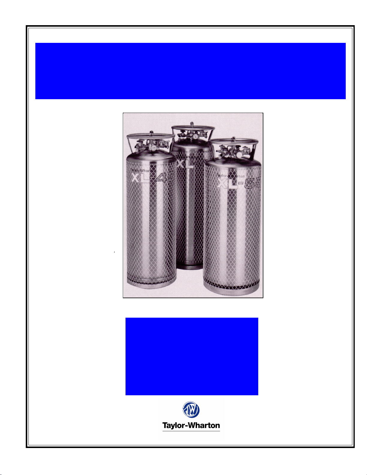
XL-45HP, XL-50HP, XL-55HP and XL-50VHP
with Dual Regulator
Do not attempt to use or maintain this
unit until you read and understand these
instructions. Do not permit untrained
persons to use or maintain this unit. If
you do not fully understand these
instructions, contact your supplier for
further information.
TW-288
1

Pressure Hazard The containers covered by this literature may contain pressures up to
350 psig (24 bar/2413 kPa for the XL-45HP/50HP/55HP and pressures up to 500 psig (34
bar/3447 kPa for the XL-50VHP. Sudden release of this pressure may cause personal
injury by issuing cold gas or liquid, or by expelling parts during servicing. Do not attempt
any repairs on these containers until all pressure is released, and the contents have been
allowed to vaporize to ensure no pressure build-up can occur.
Extreme Cold-Cover Eyes and Exposed Skin Accidental contact of the skin or eyes
with any cryogenic liquid or cold issuing gas may cause a freezing injury similar to frost-
bite. Protect your eyes and over your skin when handling the container or transferring
liquid, or in any instance where the possibility of contact with liquid, cold popes and cold
gas may exist. Safety goggles or a face shield should be worn when withdrawing liquid or
gas. Long-sleeved clothing and gloves that can be easily removed are recommended for
skin protection. Cryogenic liquids are extremely cold and will be at temperatures below -
300°F (-184°C under normal atmospheric pressure.
Keep Equipment Well Ventilated Although some of the gases used in these contain-
ers are non-toxic and non-flammable, they can cause asphyxiation in a confined area
without adequate ventilation. An atmosphere that does not contain enough oxygen for
breathing will cause dizziness, unconsciousness, or even death. These gasses cannot
be detected by the human senses and will be inhaled normally as if they were air. Ensure
there is adequate ventilation where these gasses are used and store liquid containers
outdoors or only in well ventilated are.
Repla ement Parts Must be Cleaned for Oxygen Servi e Some materials, espe-
cially non-metallic gaskets and seals, can be a combustion hazard if used in oxygen or
nitrous oxide service, although they may be acceptable for use with other cryogenic liq-
uids. Use only Taylor-Wharton recommended spare parts, and be certain parts used on
oxygen or nitrous oxide equipment marked cleaned for oxygen service. For information
on cleaning, consult the Compressed Gas Association (CGA pamphlet G-4.1, Cleaning
for Oxygen Service or equivalent industrial cleaning specifications.
Install Relief Valves in Cryogeni Liquid Lines - When installing piping of fill hose
assemblies, make certain a suitable safety relief valve is installed in each section of
plumbing between shut-off valves. Trapped liquefied gas will expand as it warms and may
burst hoses or piping causing damage or personal injury.
The XL-45HP, XL-50HP, XL-55HP and XL50VHP are vacuum insulated, stainless steel
containers designed to store and transport cryogenic liquid oxygen, nitrogen, argon, car-
bon dioxide, and nitrous oxide. Built to DOT 4L standards, these containers may be used
for over the road transportation of cryogenic fluids, as well as on-site storage and supply
in a wide range of applications.
As rugged, long holding time, self-contained gas supply systems, these cylinders are
capable of providing continuous flow rates of up to 150 cfh (3.9 cu.m/h in carbon dioxide
service, up to 110 cfh (2.9 cu.m/h in nitrous oxide service, up to 350 cfh (9.2 cu.m/h in
other gas services. The XL-45HP/50HP/55HP are designed to hold liquid with a relief valve
setting of 350 psig (24 bar/2413 kPa and the XL-50VHP with a relief valve setting of 500
psig (34 bar/3447 kPa , which provides greater holding times than lower pressure cryo-
genic containers
CONTAINER
SAFETY
NOTE:
For detailed
information on the
handling of ryogeni
liquids, refer to the
Compressed Gas
Asso iation
publi ation: P-12
Safe Handling of
Cryogeni Liquids
available from the
Compressed Gas
Asso iation, In . 1235
Jefferson Davis
Highway, Arlington,
VA 22202.
NOTE:
The Xl-50VHP is not
designed to store or
transport ryogeni
liquid nitrous oxide.
GENERAL
INFORMATION
2
SPECIFICATIONS
XL-45HP XL-50HP XL-55HP XL-50VHP
Dimensions
Diameter 20 in. (508 mm) 20 in. (508 mm) 20 in. (508 mm) 20 in. (508 mm)
Height 61 3/8 in. (1559 mm) 64 5/8 in. (1641 mm) 69 7/16 in. (1764 mm) 64 3/4 in. (1645 mm)
Weight
Empt (Nominal) 272 lb. (123 kg) 284 lb. (129 kg) 287 lb. (130 kg) 310 lb. (141 kg)
Capacit , Gross 176 liters 188 liters 208 liters 188 liters
Capacit , Useable Liquid 165 liters 176 liters 198 liters 176 liters
Weight of Contents Maximum
Based on DOT Rated Service Pressure
Carbon Dioxide 387 lb. (176 kg) 414 lb. (188 kg) 458 (208 kg) 381 (173 kg)
Ox gen 360 lb. (163 lb.) 385 lb. (175 kg) 426 (193 kg) 364 lb. (165 kg)
Nitrogen 252 lb. (114 kg) 269 lb. (122 kg) 298 lb. (135 kg) 240 lb. (109 kg)
Argon 438 lb. (199 kg) 467 lb. (212 kg) 518 lb. (235 kg) 443 lb. (201 kg)
Nitrous Oxide 368 lb. (167 kg) 393 lb. (178 kg) 435 lb. (197 kg) N/A
Normal Evaporation Rate*
(% Capacit per Da )
Carbon Dioxide 0.75%0.75% 0.75% 0.80%
Ox gen 1.4% 1.2% 1.2% 1.5%
Nitrogen 2.2% 2.0% 1.9% 2.2%
Argon 1.4% 1.2% 1.2% 1.5%
Nitrous Oxide 0.75% 0.75% 0.75% N/A
Gas Flow Rate @ NTP (STP)**
Carbon Dioxide 150 cfh (3.9 cu.m/h) 150 cfh (3.9 cu.m/h) 150 cfh (3.9 cu.m/h) 150 cfh (3.9 cu.m/h)
Ox gen, Nitrogen, Argon 350 cfh (9.2 cu.m/h) 350 cfh (9.2 cu.m/h) 350 cfh (9.2 cu.m/h) 350 cfh (9.2 cu.m/h)
Nitrous Oxide 110 cfh (2.9 cu.m/h) 110 cfh (2.9 cu.m/h) 110 cfh (2.9 cu.m/h) N/A
Relief Valve Setting 350 psig 350 psig 350 psig 500 psig
(24 bar/2413 kPa) (24 bar/2413 kPa) (24 bar/2413 kPa) (34 bar/3447 kPa)
Inner Container Bursting Disc 525 psig 525 psig 525 psig 750 psig
(36 bar/3620 kPa) (36 bar/3620 kPa) (36 bar/3620 kPa) (52 bar/5171 kPa)
Dual Pressure Building/
Economizer Regulator***
Pressure Building Setting 300 psig 300 psig 300 psig 400 psig
(20.7 bar/2068 kPa) (20.7 bar/2068 kPa) (20.7 bar/2068 kPa) (28 bar/2758 kPa)
Economizer Setting 320 psig 320 psig 320 psig 420 psig
(22 bar/2206 kPa) (22 bar/2206 kPa) (22 bar/2206 kPa) (29 bar/2896 kPa)
Design Specifications
TC 4LM 4LM N/A N/A
DOT 4LM 4LM 4LM 4LM
Gaseous Capacit
Based on DOT Rated Service Pressure
@ NTP (STP)
Carbon Dioxide 3383 cu.ft. (89 cu.m) 3619 cu.ft. (95cu.m) 4003 cu.ft. (108 cu.m) 3330 cu.ft. (88 cu.m)
Ox gen 4350 cu.ft. (114 cu.m) 4651 cu.ft. (122 cu.m) 5146 cu.ft. (135 cu.m) 4397 cu.ft. (116 cu.m)
Nitrogen 3478 cu.ft. (91 cu.m) 3712 cu.ft. (98 cu.m) 4112 cu.ft. (108 cu.m) 3312 cu.ft. (87 cu.m)
Argon 4236 cu.ft. (111 cu.m) 4516 cu.ft. (119 cu.m) 5012 cu.ft. (132 cu.m) 4285 cu.ft. (113 cu.m)
Nitrous Oxide 3211 cu.ft. (84 cu.m) 3429 cu.ft. (90 cu.m) 3796 cu.ft. (106 cu.m) N/A
Specifications are subject to change without notice.
* Vented N.E.R. based on Useable Liquid Capacit .
** Container pressure at or above factor Dual Pressure Building/Economizer Regulator setting.
*** Regulator has a pressure delta of 20 psig (1.4 bar/138 kPa).
3

Handling the Container
The XL Series containers are very rugged liquid cylinders. All cryogenic liquid containers
have an inner container and an outer container with an insulated vacuum space between
them. Any abuse (dents, dropping, tip-over, etc. can effect the integrity of the containers
insulation system.
When fully loaded, the XL-55HP in argon service will contain up to 518 lb (235 kg of
product. While moving a full container, you may be handling up to 805 lb. (365 kg , and
you should treat the load accordingly. The attachment points provided on the XL-45HP/
50HP/55HP/50VHP will allow you to use a hand truck or a hoist to handle these loads
properly. Do not attempt to move these cylinders by any other means. While moving the
cylinder, the following precautions should be observed:
qNever lay the container on its side. Always ship, operate, and store the unit in a
vertical, or upright position.
qWhen loading or unloading the container from a truck, use a hand truck, lift gate,
crane, or parallel loading dock. Never attempt to manually lift the unit.
qTo move the container over rough surfaces, or to lift the container, attach an appropri-
ate sling to the lifting points cut into the welded support posts, and use a portable
lifting device that will handle the weight of the container and its contents.
FREIGHT DAMAGE
PRECAUTIONS
ANY FREIGHT DAMAGE
CLAIMS ARE YOUR
RESPONSIBILITY. Cryogenic
liquid containers are delivered to
your carrier from Taylor-Whartons
dock in new condition. When you
receive our product you may
expect it to be in that same
condition. For your own
protection, take time to visually
inspect each shipment in the
presence of the carriers agent
before you accept delivery. If any
damage is observed, make an
appropriate notation on the freight
bill. Then ask the driver to sign
the notation before you receive
the equipment. You should
decline to accept containers that
show damage which may affect
serviceability.
XL-45HP, XL-50HP
XL-55HP, XL-50VHP
Containers
4
The XL-45HP will store up to 165 liters of product; the XL 50HP/50VHP up to 176 liters,
and 196 liters for the XL-55HP. All four cylinders can deliver either liquid or gas. The
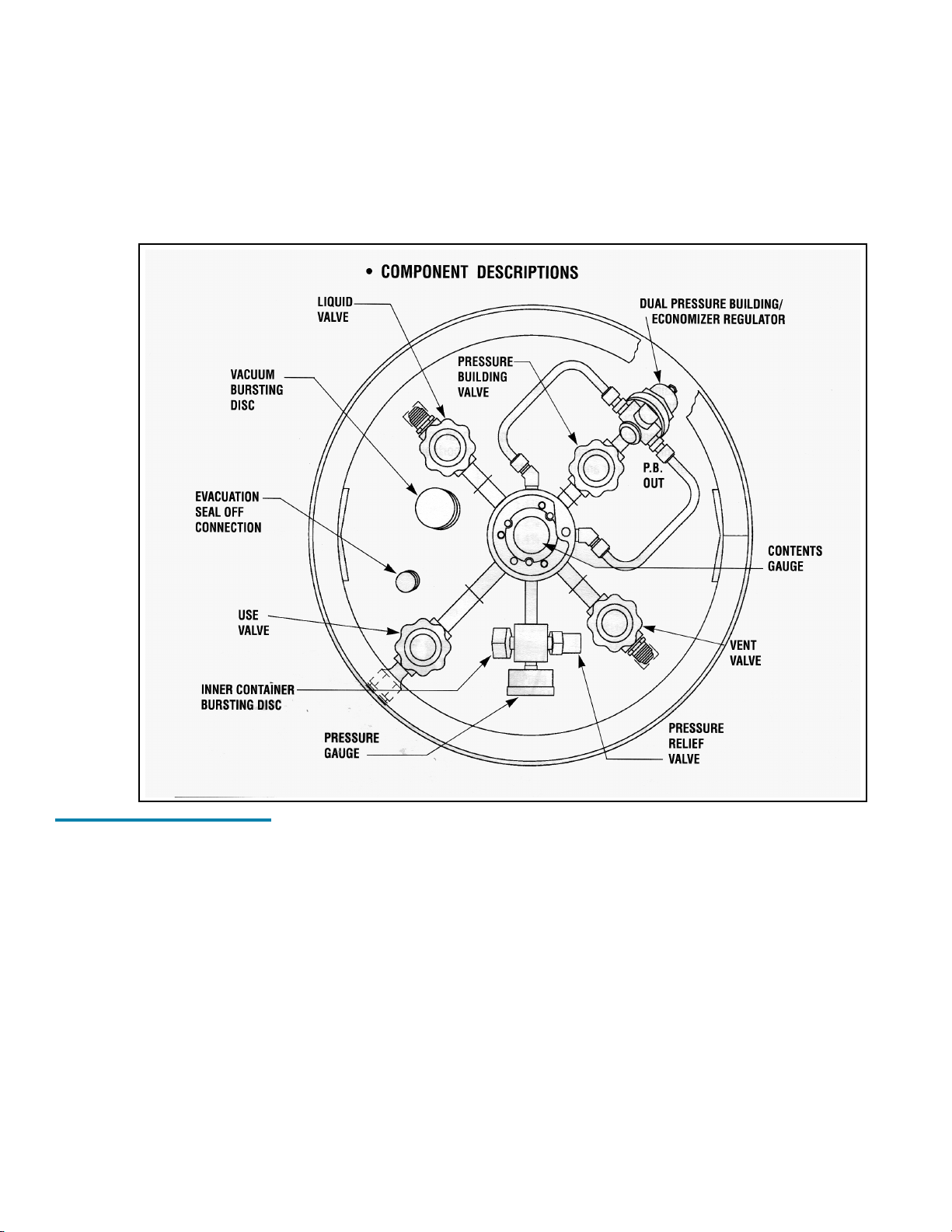
following component and circuit descriptions are pertinent to the operation of all the con-
tainers and should be read before attempting operation. The components may be identi-
fied on the Component Location Illustration.
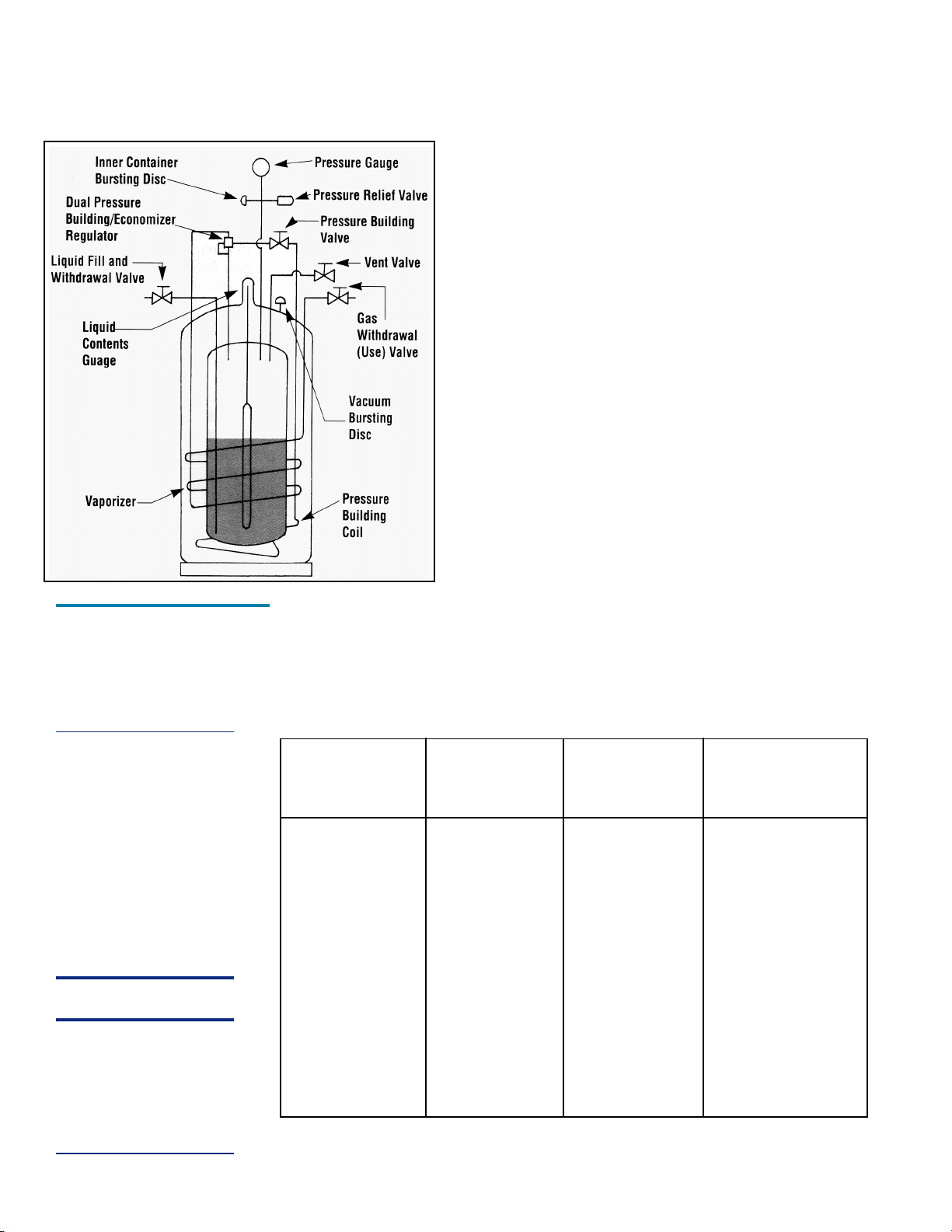
Internal Vaporizer A liquid container for gas service must have an internal heat ex-
changer that functions as a gas vaporizer coil to convert liquid product to gas continu-
ously during withdrawal. The XL-45HP/50HP/55HP/50VHP utilize an internal heat ex-
changer that is inside the vacuum space attached to the containers outer casing. It
provides a mean of introducing heat from outside the containers insulated jacket, to
vaporize liquid as gaseous product is withdrawn. The capacity of this circuit is sufficient to
vaporize at flow rates up to 350 cfh @ NTP (9.2 cu.m/h @STP . If a greater continuous
demand is put on the vaporizer, an external vaporizer should be added to properly warm
the gas and avoid malfunction, or damage, to gas regulators, hoses, and other down-
stream components.
Pressure Building A Pressure Building circuit is used to ensure sufficient driving pres-
sure during high withdrawal periods. This function is actuated by opening a hand valve that
creates a path from the liquid in the bottom of the container, through the Pressure Building
Regulator, to the gas space in the top. When the pressure building valve is open, and the
container pressure is below the pressure building regulator setting, liquid taken from the
OPERATION
XL-45HP/50HP/
55HP/50VHP
Component
Locations
5
inner container is vaporized in a heat exchanger which is inside
the outer casing. The expanding gas is fed into the upper sec-
tion of the container to build pressure. The resulting process will
drive either the liquid or gas delivery system.
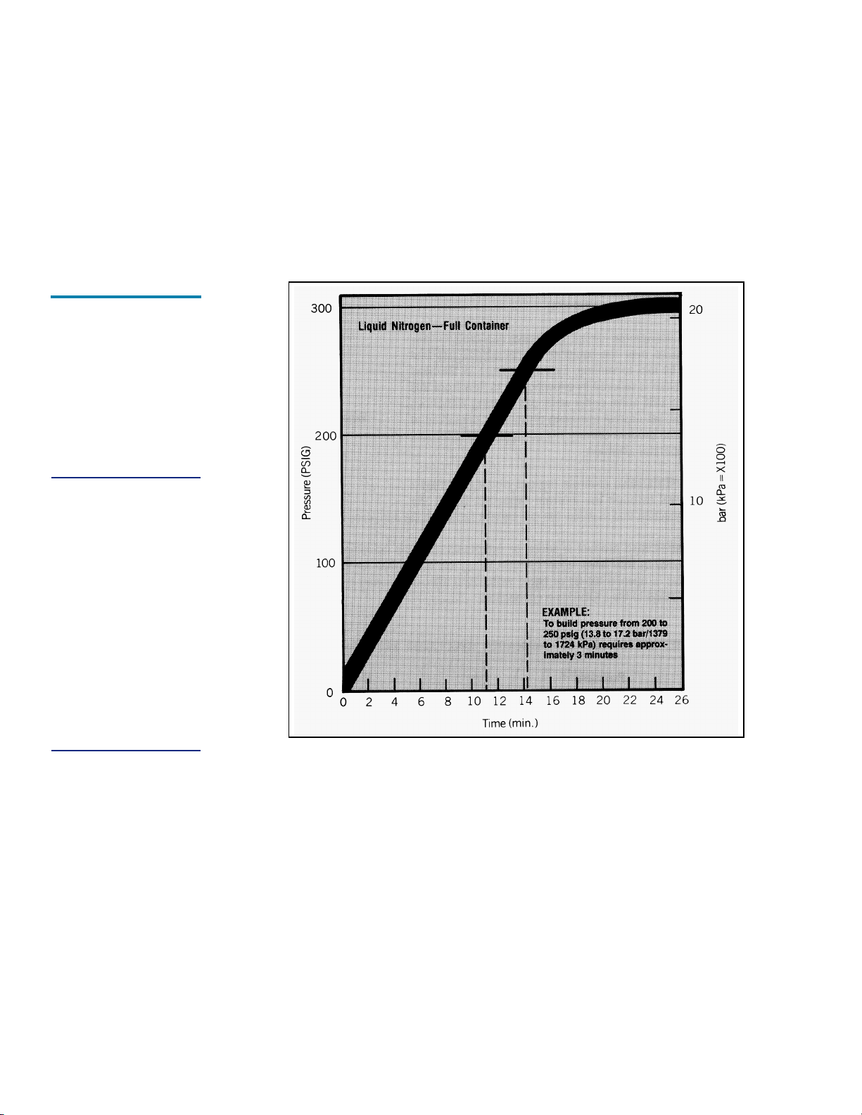
Pressure Building is not normally required unless container pres-
sure drops below the gas output pressure desired. If, for ex-
ample, the container pressure gauge reads 250 psig (17.2 bar/
1724 kPa , and your gas pressure requirement is 270 psig (19
bar/1860 kPa , and the pressure building valve may be opened
to build container pressure to 300 psig (20.7 bar/2068 kPa .
E onomizer An economizer circuit withdraws gas preferen-
tially from the head space over the liquid container gas that
would otherwise be lost to venting. Excess pressure in the head
space of the container is relieved by allowing gas to flow from
this area directly to the USE valve outlets while gas is being
withdrawn from the container; yet normal operating pressure is
preserved to ensure uninterrupted product delivery. The econo-
mizer is automatic and requires no operator attention.
The USE Valve This valve controls the gas outlet that allows
product withdrawal through the internal vaporizer. It has the re-
quired CGA connection that matches the gas service for which
the container is configured.
The LIQUID Valve Liquid product is added or withdrawn from the container through the
connection controlled by this valve. It has the CGA fitting that is required for liquid line
connections. The valve is opened for fill or liquid withdrawal after connecting a transfer
hose with compatible fittings to the LIQUID line connection.
RELIEF VALVES AND RECOMMENDED REGULATOR SETTINGS
Relief Pressure Normal
Valve Building E onomizer Operating
Setting Setting Setting Range
22 psig N/A N/A 0-22 psig
1.5 bar N/A N/A 0-1.5 bar
152 kPa N/A N/A 0-152 kPa
230 psig 125 psig 145 psig 75-175 psig
16 bar 8.6 bar 10 bar 5-12 bar
1586 kPa 862 kPa 1000 kPa 517-1207 kPa
350 psig 300 psig 320 psig 200-350 psig
24 bar 20.7 bar 22 bar 13.8-24 kPa
2413 kPa 2068 kPa 2206 kPa 1379-2413 kPa
500 psig 400 psig 420 psig 300-600 psig
34 bar 28 bar 29 bar 20.7-41 bar
3447 kPa 2758 kPa 2896 kPa 2068-4137 kPa
XL-45HP/XL-50HP/
XL-55HP and XL-
50VHP Flow
Diagram
NOTE:
The e onomizer and
pressure building
fun tions are ontrolled
by a single dual a tion
regulator. The pressure
delta between the
pressure building
setpoint and the
e onomizer setpoint is
approximately 20 psig
(1.4 bar/138 kPa). This
delta annot be altered.
WARNING:
Never use the Dual
Pressure Building/
E onomizer Regulator
or Relief Valve for the
XL-50VHP on any other
ontainer.
6
The PRESSURE BUILDING Valve This valve isolates the liquid in the bottom of the
container to the Dual Pressure Building/Economizer Regulator. This valve must be open
to build pressure inside the container.
The VENT Valve - This valve controls a line into the headspace of the container. It is used
during the fill process. The VENT valve acts as a fill point during the pump transfer, or to
vent the head space while liquid is filling the inner container during the pressure transfer fill
through the LIQUID Valve.
The Pressure Gauge - The pressure gauge displays the internal container pressure in
pounds-per-square-inch or in kiloPascals.
The Full View Contents Gauge The container contents gauge is a float type liquid
level sensor that indicates container liquid content through a magnetic coupling to a
yellow indicator band. This gauge is an indication of approximate container contents only
and should not be used for filling; liquid cylinders should be filled by weight.
Relief Devi es These cylinders have a gas service relief valve and inner container
bursting disc with settings of 350 psig (24 bar/2412 kPa and 525 psig (36 bar/3620 kPa
respectively for the XL-45HP/50HP/55HP and 500 psig (34 bar/3447 kPa and 750 psig
(52 bar/5171 kPa for the XL-50VHP. Relief valves of 230 psig (16 bar/1586 kPa and 22
psig (1.5 bar/152 kPa are available if medium pressure operation is desired. Alternate
pressure building regulator and economizer settings are required if medium-pressure re-
lief valves are installed.
CAUTION:
When withdrawing
liquid gas from the
ylinder, the apa ity
of the internal
vaporizer an be
ex eeded. If gas is
withdrawn at rates
greater than the
vaporizer apa ity,
liquid or very old gas
will be dis harged.
Severe damage to
external equipment
ould result from the
extreme old.
Pressure
uilding Rates
Graph
7

WITHDRAWING GAS FROM THE CONTAINER
To withdraw gas from the XL-45HP/50HP/55HP/50VHP connect a suitable pressure regu-
lator to the USE connection, and the output of the regulator to your external equipment.
Then open the USE connection, and the output of the regulator to your external equip-
ment. Then open the USE and the PRESSURE BUILDING valves. When the container
pressure reaches 125 psig (8.6 bar/862 kPa , 300 psig (20.7 bar/2068 kPa or 400 psig
(28 bar/2758 kPa if equipped with the higher valve Dual Pressure Building/Economizer
regulator set the pressure regulator for the desired delivery pressure.
In reasing Gas Supply Capa ity Two or more liquid containers may be manifolded
together. Accessory manifolds are available for use in creating a higher capacity gas
supply system. The XL-45HP/50HP/55HP/50VHP can supply gas at flow rates 1 up to
350 cfh @ NTP (9.2 cu. m/h @ STP using only its internal vaporizer. At low flow rates, the
gas supplied will be at near ambient temperature. As the flow demand is increased, the
gas will become proportionately colder. If greater vaporizing capacity is required, an ac-
cessory external vaporizer is available. When an external vaporizer is sued, it must be
connected to the USE valve and the regulator moved to the output of the external vapor-
izer.
WITHDRAWING LIQUID FROM THE CONTAINER
When a container is used to supply liquid product, such as in an application as portable
distribution container for carbon dioxide, liquid may be withdrawn from the XL-45HP/50HP/
55HP/50VHP.
Attach a transfer hose to the LIQUID connection and open the adjacent LIQUID valve. The
presser in the container will drive liquid product out through the valve as the container
pressure exceeds that of the receiver.
The rate of liquid withdrawal from these containers is variable depending on the gas phase
pressure and the saturation temperature of the liquid.
1 See Specifications for your application.
CAUTION:
Internal orifi es in
pressure regulators
used with CO2 are
subje t to the
formation of dry i e if
ex essively old gas
or high flow rates are
used. If this ondition
o urs, an external
vaporizer should be
used to ensure the gas
is warmed before it
rea hes the regulator.
Vaporizer Performance Graph
Liquid Withdrawal
CAUTION:
To avoid
ontamination, lose
the LIQUID valve on
an empty ontainer
before dis onne ting
the transfer line.
8
FILLING THE CONTAINER
Cryogenic liquid containers must always be filled by weight to ensure there is enough gas
head space (ullage for liquid to expand as it warms. Using the procedure bellow, first
determine the proper filled weight of each container. The weight derived is then used in
either the Pump Transfer of Pressure Transfer filling procedures that follow.
Determining Proper Fill Weight
1. Visually inspect the container. Do not attempt to fill containers with broken or missing
components.
2. Move the container to a filling station scale and weight it both with and without the fill
hose attached to determine the weight of the fill line assembly. The difference is the fill
line weight.
3. To determine the weight, at which the fill should be stopped, add the desired filling
weight (from the table below , the transfer line weight, and the Tare Weight from the
containers data plate.
FILLING WEIGHTS
XL-45HP XL-50HP XL-55HP XL-50VHP
ARGON 438 lb. (199 kg) 467 lb. (212 kg) 518 lb. (235 kg) 443 (201 kg)
CARBON 387 lb. (176 kg) 414 lb. (188 kg) 458 lb. (208 kg) 381 lb. (173 kg)
DIOXIDE
NITROGEN 252 lb. (114 kg) 269 lb.(122 kg) 298 lb. (135 kg) 240 lb. (109 kg)
NITROUS 368 lb. (167 kg) 393 lb. (178 kg) 435 lb. (197 kg) N/A
OXIDE
OXYGEN 360 lb. (163 kg) 385 lb. (175 kg) 426 lb. (193 kg) 364 lb. (165 kg)
Solid CO2 (Dry I e) Formation - Carbon dioxide may form into the solid phase (dry ice
if the saturated pressure of the liquid is allowed to drop below 70 psig (4.8 bar/483 kPa.
In carbon dioxide service, the pressure in a XL-45Hp/50HP/55HP/50VHP must be main-
tained above this pressure to ensure a solid block will not form inside the container. If a
container is being filled with CO2, it may be necessary to pressurize the container with
gaseous CO2 before beginning the fill.
Pressure Transfer Filling Method
Filling a liquid cylinder using the pressure transfer method is common for 22 psig (1.5 bar/
152 kPa service where the product is used for refrigerant purposes. This method may
also be used for higher-pressure cylinders to increase liquid holding time. A fill is accom-
plished by first establishing a pressure difference between source vessel and the XL-
45Hp/50HP/55HP/50VHP (higher pressure at the bulk vessel . The pressure differential
will then push the liquid from the storage vessel to the container being filled. This method
is employed when no transfer pump system is available, or if a greater control over liquid
temperature is desired.
Filling the container is accomplished through the LIQUID valve while the VENT valve is
open or partially open to control product pressure. Careful control of pressure will control
the amount of heat retained in the liquid. Lower pressure results in colder liquid trans-
ferred to the container and increases, or lengthens, product holding time.
NOTE:
The weight
al ulation in ludes
the weight of residual
liquid and is
appli able to both
Pressure Transfer and
Pump Transfer filling
methods.
WARNING:
Filling operations
should take pla e only
in well ventilated
areas. A umulations
of produ t gas an be
very dangerous (refer
to the safety
pre autions in the
front of these
instru tions). Maintain
adequate ventilation
at all times.
NOTE:
If the pressure in the
ontainer is somehow
lost, the dry i e blo k
that forms may be
thawed by
pressurizing the
ylinder to 280 psig
(19.3 bar/1931 kPa)
with arbon dioxide
liquid and gas from an
external sour e, and
allowing several days
at this pressure to
thaw the ylinder.
9

Pressure Transfer Filling Pro edure (Low Pressure Sour e) - Once you have deter-
mined the proper full weight for a container, connect a transfer hose to the LIQUID fitting
from a low-pressure source of liquid.
1. Open the supply valve. Then, on the XL-45HP/50HP/55HP/50VHP, open the LIQUID
and VENT valves to begin the fill.
2. During the fill, monitor the container pressure and maintain a pressure of 10-15 psig
(0.7-1 bar/69-103 kPa by throttling the VENT valve. Not for CO2 service.
3. When full weight is reached, close both the LIQUID and VENT valves.
4. Close the liquid supply valve and open the dump valve on fill line assembly.
5. Disconnect the fill line from the container and remove the container from the scale.
Pump Transfer Filling Method
When a pump is used for filling liquid containers, the fill may be accomplished through
either the VENT valve or the LIQUID valve. Filling through the VENT valve recondenses
gas in the area over the liquid in the cylinder and reduces product loss during the fill. This
method will also result in liquid near the saturation temperature of the supply vessel.
Filling through the LIQUID valve may provide colder liquid and longer holding time before
the liquid warms to the point where venting gas begins, but will require more frequent
venting and greater product loss.
Pump Transfer Filling Pro edure This method applies only to containers in gas
service that are equipped with a 230 psig (16 bar/1586 kPa0, 350 psig (24 bar/2413 kPa
or 500 psig (34 bar/3447 kPa relief valve. Liquid is admitted through the vent valve and
recondenses gas in the head space during the fill. The fill line is connected from the liquid
supply to the VENT valve on the cylinder. Both the fill line and the container should be pre-
cooled prior to beginning the fill process. Proper full weight is determined by the previ-
ously explained method.
1. Open the supply valve. Then, on the container being filled, open only the VENT valve to
begin the fill. Start the pump at this time.
2. Observe the container pressure closely. If the pressure approaches the relief valve
setting (or the pump pressure rating stop the fill process at the supply, and open the
fill line dump valve to vent excess pressure. As soon as the pressure has dropped to a
level that will allow you to resume the fill, close the dump valve and restart the pump (or
reopen the supply valve.
3. When full weight is reached, close the VENT valve. Stop pump (where applicable ,
close liquid supply valve and open the dump valve on fill line assembly to vent trapped
liquid.
4. Disconnect the fill line from the container and remove the container from the scale.
Fill Hose Kits
Taylor-Wharton fill hose kits for the XL-45/50HP/55HP/50VHP are designed to transfer
specific liquefied gases to, or from, the containers. These accessories are comprised of a
Fill Tee Assembly and a Fill Hose. Cryogenic transfer hoses are constructed of stainless
steel for the transfer of cryogenic liquids, and are available in four or six feet (1.2 or 1.8 m
lengths with a 3/8 in. NPT fitting on one end and CGA service-specific female fittings on
the other. A Fill Tee Assembly consists of a cross fittings with a CGA end fitting, relief
valve and manual dump valve.
CAUTION
With arbon dioxide,
pressure in the
ontainer being filled
must be above 70 psig
(4.8 bar/483 kPa)
before the fill begins
and at all times during
the fill to prevent the
produ t from freezing
into dry i e.
Pump Transfer Liquid
Fill Through Vent Valve
Pressure Transfer
Filling From a Low
Pressure Source
10
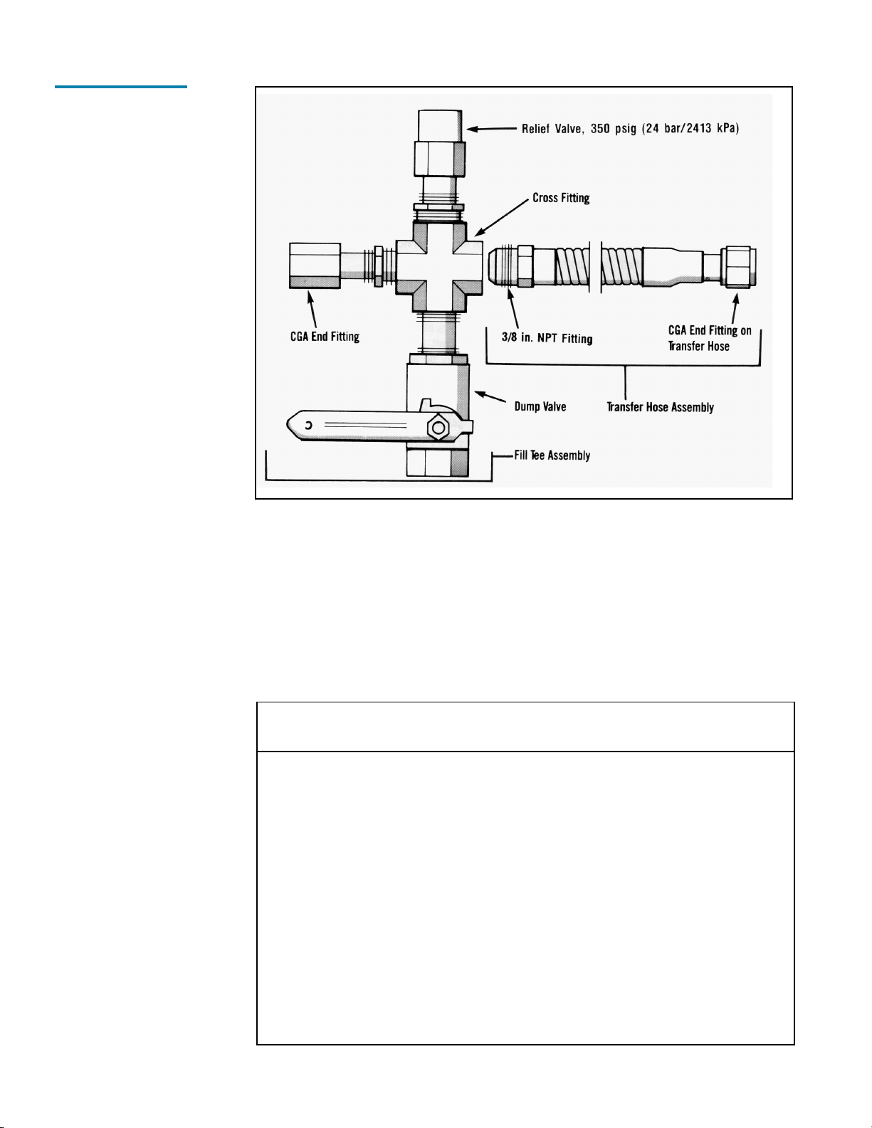
In use, the CGA Tailpiece couples to the fill connection on the container being filled. The
Relief Valve vents pressure over 350 psig (24 bar/2413 kPa that builds up in the fill line
due to trapped liquid. The Dump Valve is used to allow the operator to blow-don the
receiving container during a pump fill, or to relieve residual pressure from expanding liquid
trapped in the line before disconnecting the fill line.
Fill kits are available with different combinations of hose length and fittings for a specific
gas service. The following chart identifies the available transfer hoses and fill tee assem-
blies.
TRANSFER HOSE CHART
Des ription Cylinder End Part
(Servi e/Hose Length) Conne tions(s) Fittings Number
Inert (N2,Ar) Service
4 ft. (1.2 m) Stainless Steel LIQUID or VENT Valve CGA 295 to 3/8 in. NPT 1700-9C65
6 ft. (1.8 m) Stainless Steel LIQUID or VENT Valve CGA 295 to 3/8 in. NPT 1600-9C66
6 ft. (1.8 m) Stainless Steel USE Valve CGA 580 to 3/8 in. NPT GL50-8C51
Oxygen Service
6 ft. (1.8 m) Stainless Steel LIQUID or VENT Valve CGA 440 to 3/8 in. NPT GL50-8C53
6 ft. (1.8 m) Stainless Steel USE Valve CGA 540 to 3/8 in. NPT GL50-8C56
Car on Dioxide Service
6 ft. (1.8 m) Stainless Steel LIQUID or USE Valve CGA 320 to 3/8 in. NPT HP50-8C51
4 ft. (1.2 m) Stainless Steel VENT Valve CGA 295 to 3/8 in. NPT 1700-9C65
6 ft. (1.8 m) Stainless Steel VENT Valve CGA 295 to 3/8 in. NPT 1600-9C66
Nitrous Oxide Service
4 ft. (1.2 m) Stainless Steel VENT Valve CGA 295 to 3/8 in. NPT 1700-9C65
6 ft. (1.8 m) Stainless Steel VENT Valve CGA 295 to 3/8 in. NPT 1600-9C66
Fill Hose Kits
11
VENT TEE CHART
The vent tee chart connects to a transfer hose to complete a fill line kit. Each assembly
includes a 3/8 in. pipe connector to CGA fitting with a 350 psig (24 bar/2413 kPa relief
valve, and a ball-type dump valve.
Servi e CGA Conne tion Part Number
Inert (N2, Ar CGA 295 GL50-8C60
Read the Safety Precautions in the front of this manual before attempting any repairs on
these containers. Also follow these additional safety guidelines while performing con-
tainer maintenance.
Never work on a pressurized ontainer. Open the vent valve as a standard practice
during maintenance to guard against pressure build-up from residual liquid.
Use only repair parts leaned for oxygen servi e. Be certain your tools are free of oil
and grease. This is a good maintenance practice, and helps ensure you do not create a
combustion hazard when working on containers for oxygen or nitrous oxide service.
Leak test onne tions after every repair. Pressurize the container with an appropriate
inert gas for leak testing. Use only approved leak test solutions and follow the manufacturers
recommendations. Snoop Liquid Leak Detector is one approved solution, it is available
from: Nupro Co., 4800 E. 345th St., Willoughby, Ohio, 44094 U.S.A.
CONVERTING A CONTAINER TO A DIFFERENT GAS SERVICE
XL-45HP/50HP/55HP/50VHP cylinders may be converted from one service to another
within the confines of the argon, carbon dioxide, nitrogen, nitrous oxide, and oxygen
service for which the containers are designed. Conversion consists of changing end con-
nections at the USE, LIQUID and VENT valves; then changing the liquid level gauge scale
by changing its plastic cover; and revising product decals. Parts are available in kit form
for each gas service as illustrated in the following table.
Servi e Change Pro edure
Before removing any parts, empty the container and open the vent valve to prevent any
pressure build-up in the unit.
1. Remove the LIQUID, VENT and USE end fittings, one at a time, with standard wrenches.
Install new fittings from the Gas Service Change Kit, using Teflon tape or another
oxygen-compatible thread sealant.
2. Remove the protective cover over the liquid level gauge. Replace the contents scale
with the scale for the new gas service from the service change kit, then replace the
protective cover.
3. Install new fittings for the USE, VENT and LIQUID connections from the Gas Service
Change Kit. Leak test the fittings you just replaced, and change the gas service de-
cals to complete the conversion.
WARNING:
Never put any liquid
ylinder into another
servi e on e it has
been in CO2 servi e.
MAINTENANCE
PROCEDURES
WARNING:
For O2 users: Residue
of leak dete tors
solutions an be
flammable. All
surfa es to whi h the
leak dete tor solutions
have been applied
must be adequately
rinsed with potable
water to remove all
tra es of residue.
Referen e CGA G-4,
Se tion 5.9
CAUTION:
Carbon dioxide may
form into the solid
phase (dry i e) if the
pressure of the liquid
is allowed to drop
below 70 psig (4.8 bar/
483 kPa). Pressure in
the ontainer must be
maintained above this
value to ensure a solid
blo k of CO2 will not
form inside the
ontainer. Before
performing
maintenan e on an
XL-45HP/50HP/55HP/
50VHP in CO2 servi e,
the ontents must be
transferred to another
ontainer so that
ontainer pressure
an be released.
12

GAS SERVICE CHANGE KITS
Kit Valve Conne tion
Part No. Gas Servi e Name Designation
GL50-8C35 Oxygen LIQUID CGA 440
VENT CGA 440
USE CGA 540
GL50-8C30 Nitrogen LIQUID CGA 295
VENT CGA 295
USE CGA 580
GL50-8C31 Argon LIQUID CGA 295
VENT CGA 295
USE CGA 580
HP50-8C30 Carbon Dioxide LIQUID CGA 320
VENT CGA 295
USE CGA 320
HP50-8C35 Nitrous Oxide LIQUID CGA 326
VENT CGA 295
USE CGA 326
REGULATOR MAINTENANCE
A dual stage, spring loaded regulator is employed for the pressure building/economizer
circuit. This regulator can be adjusted on the container, replaced or checked and adjusted
off the container in a readily fabricated bench adjustment fixture.
Regulator Adjustment On Container
1. Fill the container with the appropriate liquid product.
2. Open the Pressure Building Valve and allow the container pressure to stabilize for
about an hour. Note the point where the pressure stabilizes.
3. Adjust the screw on the top of the regulator to raise or lower the pressure to the
desired point. When decreasing the setting, the pressure building valve must be closed
and the container vented to a lower pressure. Then repeat step 2 in order to observe
the change.
REGULATOR ADJUSTMENT RANGES
Part No. Normal Setting Range Delta
8816-1060 400 psig 300 to 600 psig
28 bar 20.7 to 41 bar
2758 kPa 2068 to 4137 kPa
6999-9018 300 psig 200 to 350 psig 20 psig
20.7 bar 13.8 to 24.1 bar 1.4 bar
2068 kPa 1379 to 2413 kPa 138 kPa
6999-9015 125 psig 75 to 175 psig
8.6 bar 5 to 12 bar
862 kPa 517 to 1207 kPa
CAUTION
When hanging gas
servi e, install the
proper fittings DO NOT
use adapters. The
following pro edures
address the physi al
hanges to the ontainer
only. For detailed
pro edures on the
de ontamination of the
ontainer itself, refer to
CGA pamphlet C-10
Changes of Servi e for
Cylinders In luding
Pro edures for
Inspe tion and
Contaminant Removal.
CAUTION
Carbon Dioxide and
Nitrous Oxide may
ontain ontaminants
su h as hydro arbons,
that are not easily
removed from ylinders,
and asso iated with
omponents by
onventional oxygen
servi e leaning
pro edures. On e a
ylinder is pla ed into
CO2 or N2O gas servi e, it
should never be
onverted to another gas
servi e. See CGA
pamphlet C-10 for proper
pro edures.
NOTE:
One lo kwise turn of
the adjustment will raise
the setpoint by
approximately 30 psig (2
bar/207 kPa). See the
hart below to
determine the range of
adjustment for the
regulator you are
servi ing. Do not attempt
to set the regulator to a
pressure outside of its
design range.
13
Regulator Removal or Repla ement Pro edure
1. Close manual Pressure Building valve.
2. Vent the container to atmospheric pressure. 2
3. Loosen and remove both the tube connections on the pressure building and econo-
mizer output sides of the regulator.
4. Remove the regulator from the container by unscrewing the valve body and elbow from
the output of the Pressure Building Valve.
5. Repair the regulator and readjust its setpoint using the bench test setup.
6. To install a replacement or readjusted regulator, apply Teflon tape to the elbow on the
container and thread the valve body onto the elbow.
7. Reconnect the tube connections to the regulator and tighten.
8. Pressurize the container and check it for leaks.
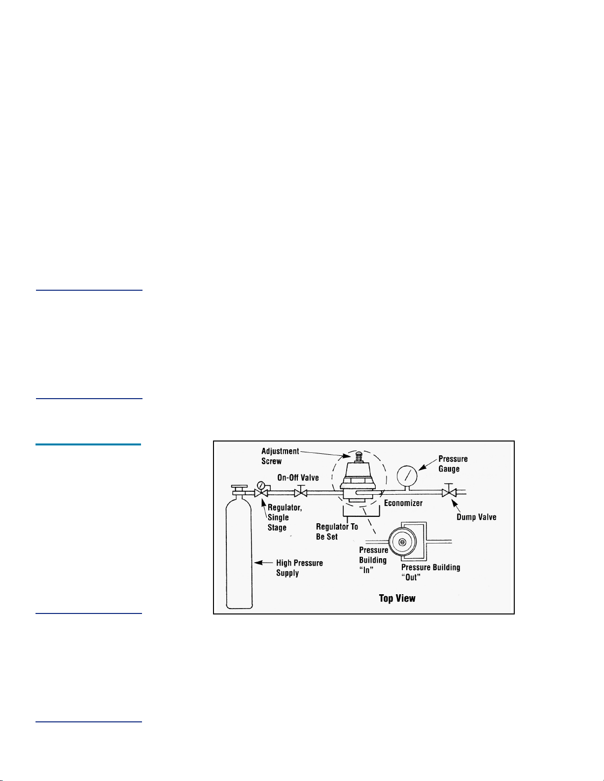
Regulator Adjustment Ben h Pro edure
Assemble the regulator adjustment fixture, and the regulator to be adjusted, as shown in
the accompanying illustration.
1. Leak test joints between high pressure cylinder regulator and the dump valve. Joints
must be leak free before proceeding.
2. Close the on/off valve and the Dump valve.
3. Slightly open the high pressure cylinder valve.
4. Set the high pressure regulator above the desired set point for the Pressure Building
setpoint.
5. Slowly open the on/off valve and observe the downstream pressure gauge.
6. When the regulator under test closes, the P.B. set point may be read on the down-
stream pressure gauge.
7. Close the on/off valve and open the Dump valve.
8. To reset the regulator, loosen the lock nut on the adjusting screw. Raise the set point
by turning the adjusting screw clockwise; lower the setpoint by turning the screw
counter clockwise. After adjustment, repeat steps 5 and 6 to check the setting before
reinstalling the regulator on the liquid container.
2 For units in C02 service, see caution for releasing pressure at the beginning of the Maintenance Section.
NOTE:
The regulator has
dire tional gas flow.
The arrow on the
regulator body must
put in the dire tion
indi ated in the Ben h
Adjustment Fixture
illustration.
Regulator
ench
Adjustment
Fixture
NOTE:
The e onomizer
portion of the
regulator has already
opened approximately
20 psig (1.4 bar/138
kPa) below the
pressure building
setpoint.
14

CHECKING CONTAINER PERFORMANCE
Cryogenic containers are two containers, one within the other. The space between the
containers acts as a highly efficient thermal barrier including high technology insulation, a
vacuum, and a vacuum maintenance system. Each serves a very important part in the
useful life of the container. The high technology insulation is very effective in preventing
radiated hear from entering the inner container. The vacuum prevents heat convection or
conduction from reaching the inner container. Unfortunately, the perfect vacuum cannot
be achieved since trace gas molecules being to enter the vacuum space from the moment
of manufacture. The vacuum maintenance system can perform its function for years, but
it has a limited capacity. When the vacuum maintenance system is saturated it can no
longer maintain the vacuum integrity of the container. The change will be very gradual and
my ago unnoticed for several years. When the vacuum in the insulation space is no longer
effective, the following symptoms may appear:
1. With liquid in the container and pressure building/vaporizer coil not in use, the outer
casing will be much colder than comparative containers.
2. Frost, indicating the liquid level, may be visible on the outer casting of container.
3. The container may appear to sweat if the air surrounding the container is hot and
humid.
4. The relief valve will open continuously until the container is empty.
5. The container will hold pressure for several days but will not hold liquid.
NER Testing
If a loss of vacuum integrity is suspected, the containers Normal Evaporation Rate (NER
should be checked. The test measures the actual product lost over time so you can
compare the results obtained to the NER value in the SPECIFICATIONS table. A test
period of 48 hours recommended, after the container is allowed to stabilize, but the for-
mula given produces a Daily NER over any time period.
1. Fill the container with 150 pounds (68 kg of liquid nitrogen.
2. Close the LIQUID valve and the PRESSURE BUILDING valve, leave the VENT valve
open and allow it to remain open during test.
3. Allow the container to stabilize for 24 hours, then reweigh it. Record the weight, time,
and date.
4. Reweigh 48 hours later. The test is most effective if container is not moved during this
period. Record the second test date, time and weight.
The following calculation will provide Normal Evaporation Rate in pounds-per-day. Daily
normal evaporation is simply half the loss over 48 hours.
Daily NER = Weight (Step 3 Weight (Step 4 x 24
Time between Step 3 and Step 4 in hours
Compare the results of your test to the as manufactured NER value in the SPECIFICA-
TIONS section of this manual. A container in service should maintain an NER value of less
than two times the new specification. Any test result greater than two times the listed
value is indicative of a failed, or failing, vacuum. If NER is found to be high, contact Taylor-
Wharton Customer Service at (334 443-8680 for disposition.
NOTE:
Fill through the LIQUID
valve with the VENT
valve open. The
Pressure Building
valve must be losed
during the NER rest or
P.B. operation will
in rease evaporation
and invalidate test
results
15

FULL VIEW CONTENTS GAUGE MAINTENANCE
The content of these containers is measured with the Full View Contents Gauge. The
device consists of the gauge assembly beneath a clear plastic protective cover. When the
gauge is assembled, a level indicator ring is magnetically coupled to the top of a float rod
and moves up or down with the changing level of liquid in the container. The clear cover
over the gauge body and level indicator is sealed at assembly to resist fogging of the
gauge. This seal should never need to be broken.
Removing the Full View Contents Gauge
1. Vent all pressure from the container.3
2. Remove the protective cover by removing three bolts from the base of the cover.
3. Unscrew the gauge body using a wrench on hex fitting as base of the indicator.
4. Life the entire gauge assembly free of the container. The gauge assembly is long and
may be very cold. Gloves should be used to protect your skin.
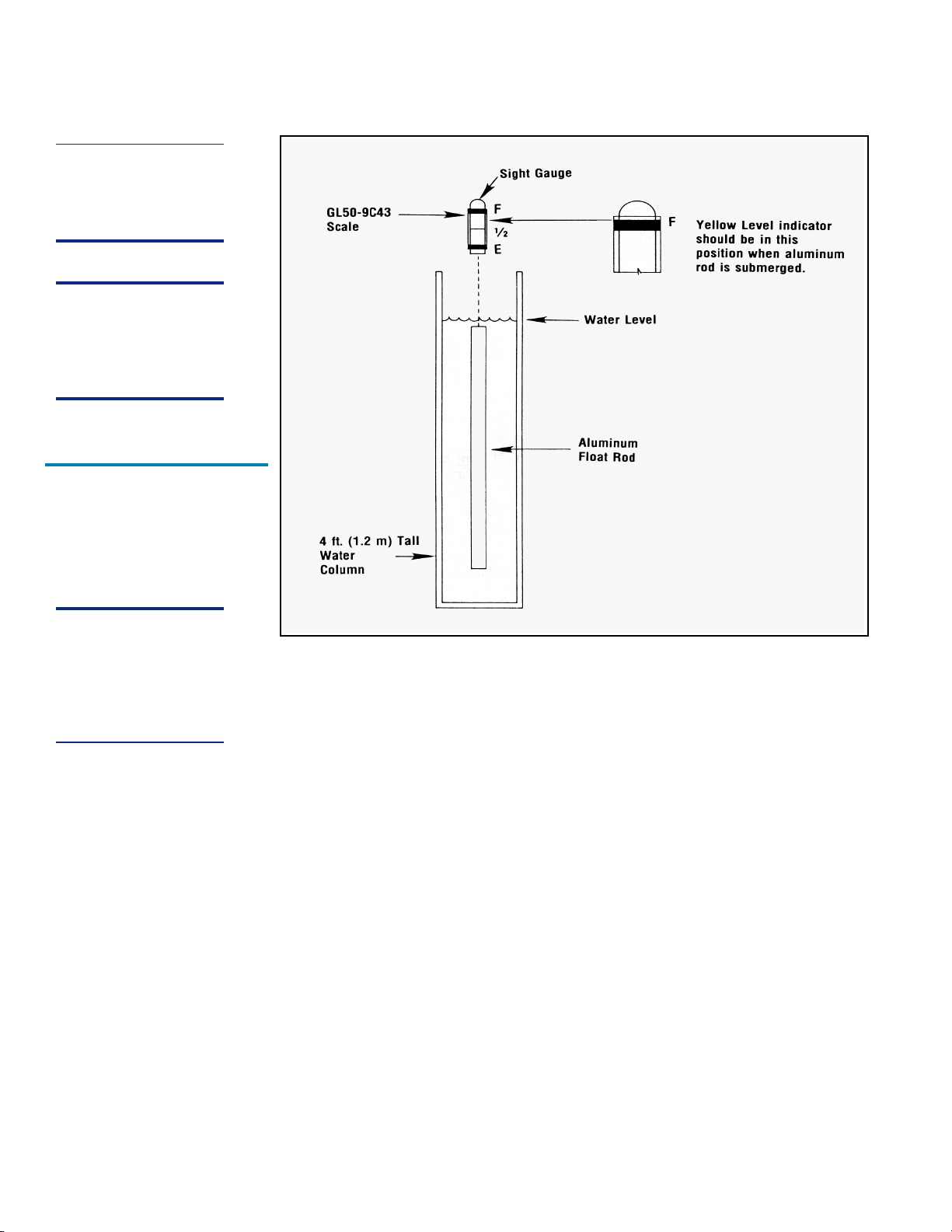
Calibration Pro edure for Liquid Level Contents Gauges
1. You will need a column of water approximately 4 ft. (1.2 m tall. A clear plastic tube 2.0
in. (51 mm dia. with a cap glued to one end is perfect. Place an oxygen service
contents scale sleeve (P/N GL50-9C43 over the sight tube.
2. Support the gauge assembly by holding the base of the indicator tube. Care must be
taken to prevent interference with the spring action or from misaligning the scale sleeve.
Immerse the aluminum float rod below the water level as illustrated. The gauge assem-
bly must be held vertically and the rod must not touch the side or bottom of the tube.
The yellow level indicator of the gauge should indicate a full level reading with the
oxygen scale.
If the gauge fails to indicate a full liquid level, the assembly is to be removed from the
water, calibrated and retested.
To change calibration, loosen locking nut away from brass calibration nut and turn the
threaded rod with respect to the calibration nut.
If the rod is turned clockwise (to the left with respect to calibration nut, the exposed
portion of rod becomes longer and the gauge yellow band will be lowered.
To raise the yellow band, turn rod counterclockwise. The exposed portion of rod becomes
shorter. Once you have adjusted calibration, recheck for proper setting. (See illustration.
After proper setting has been obtained, lock down nut against calibration nut.
3. Once the gauge assembly has been calibrated to read full in water, it must be verified that
it reads empty when the aluminum float rod is suspended in the air. The yellow indicator
must be as close to the bottom as possible (inner rod will be firmly bottomed out .
If calibration is required to make the gauge read empty in air, it must be rechecked in
water.
4. After calibration, you will need to follow contents gauge installation to reinsert gauge.
Be sure to dry the assembly before reinserting into the cylinder to prevent ice build-up
that could restrict movement to catch on the guide ring inside the cylinder.
3 For containers in C02 service, see caution on releasing container pressure at the beginning of the
Maintenance section.
WARNING:
Cold surfa es should
never be handled
with bare skin. Use
gloves and other
prote tive lothing
when performing this
pro edure.
Full View Contents
Gauge
16
Contents Gauge Installation
Before installing a new or repaired gauge, inspect the gasket seals. If any damage is
apparent, replace the gasket. (See following page for illustration.
1. When inserting the gauge assembly, lower the float rod through the gauge opening
until about 8 in. (203 mm of the float rod remains above the container.
2. Grasp the clear cover portion of the gauge assembly with two fingers so that the
assembly hangs free and plumb.
3. Lower the assembly about 4 in. (102 mm slowly and try to keep the rod in the center
of the threaded entrance hole as you do. If you are careful during this portion of inser-
tion, you will drop the float rod straight through the guide ring inside the cylinder.
4. To confirm that the rod is correctly positioned in the cylinder, stop where you can still
grasp the top of the rod (see illustration and try to swing the lower end from side to
side.
5. When rod is engaged in the guide ring, the rod will be restricted to lower end movement
of about ½ in. (12.7 mm ; if you can feel greater movement, withdraw the rod to the
point where its top is 8 in. (203 mm above the gauge opening and try again.
NOTE:
The yellow band will
move approximately
¼ in. (6.4 mm) to ea h
10 turns of the rod.
NOTE:
Remember this
pro edure is
performed with gauge
in an upright (verti al)
position.
NOTE:
Make sure that the
Gauge Assembly is not
bent or out of line
before reinserting the
gauge into the
ontainer.
Calibration
for XL-45HP, XL-50HP,
XL-55HP & XL50VHP
17

6. When you are satisfied that the float rod is correctly installed, lower the assembly the
rest of the way into the container until the top portion threads can be engaged.
7. Screw the gauge in place and hand torque to about 20 ft lbf (2.8 kgf m . Leak check the
connection of gauge body to the flange.
CAUTION:
When installing the
gauge assembly, are
must be taken to
ensure that the float
rod is inserted through
the guide ring
lo ated on the liquid
withdrawal line inside
the ontainer. If the
gauge does not
engage this ring, the
ontents indi ation
will be ina urate, or
the gauge may be
damaged in use.
Contents Gauge
Insertion
18
HAND VALVE REPAIR
Hand valves are an integral part of the container, and the valve bodies rarely need replace-
ment. However, the handwheel and the internal parts of the valve are renewable. The
illustration below are exploded views of the valves replaceable parts used on Taylor-
Wharton liquid containers.
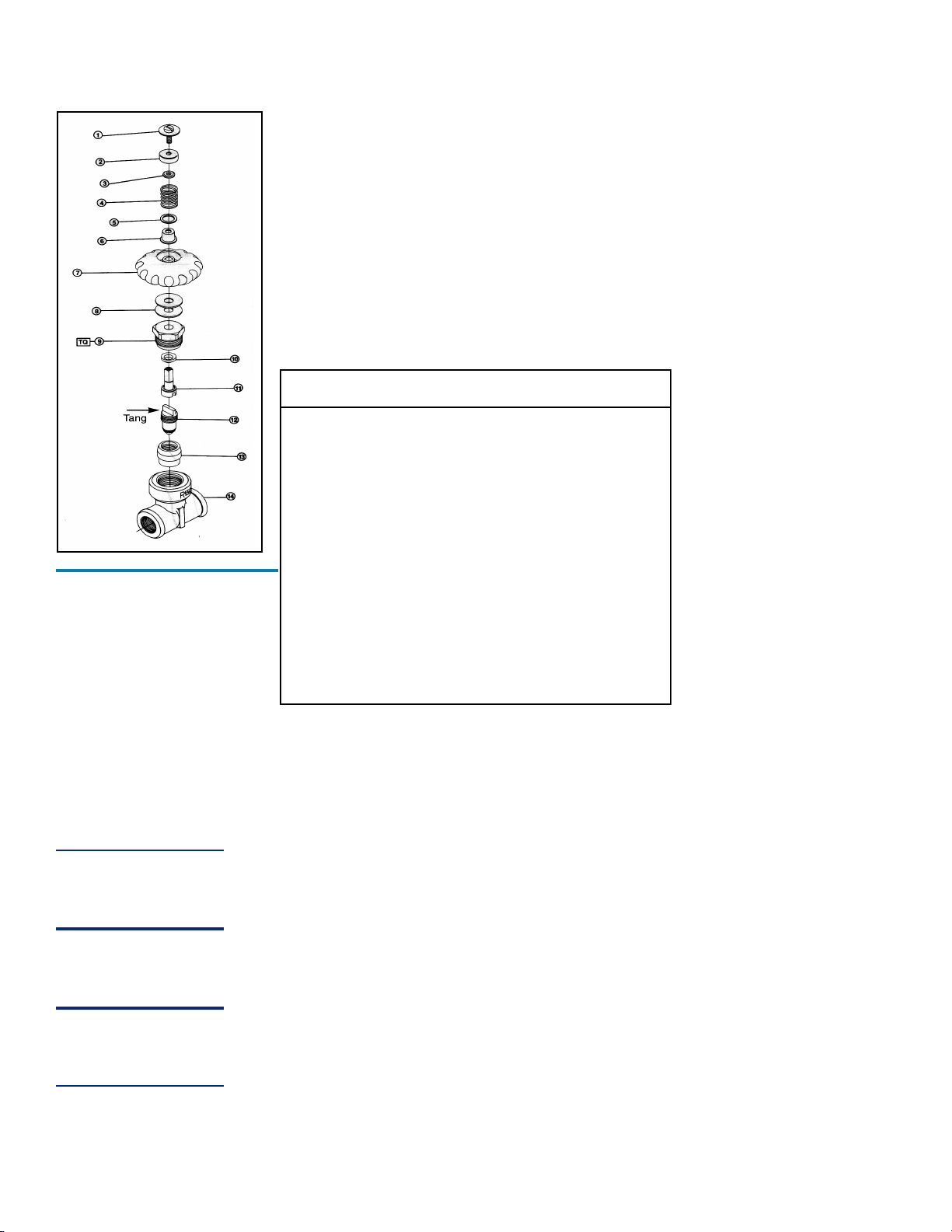
Valve Repair Kit
Fits 3/8 in. or ½ in. Rego Globe or 3/8 in. Sherwood valves.
KIT PARTS - KIT P/N 1750-9C35
Item No. Des ription Qty.
1 Screw and Washer 1
2 Spring Retainer 1
3 Retainer Washer 1
4 Spring 1
5 Seal Washer 1
6 Seal 1
7 Handwheel 1
8 Bonnet Washer 2
9 Bonnet 1
10 Stem Gasket 1
11 Stem 1
12 Seat Assembly 1
13 Bushing 1
14 Body *
TQ Torque 80 ft. lbf (11 kgf m 1
*Not available as a repair part
Valve Disassembly Instru tions
1. Open valve by turning handwheel counterclockwise as far as it will go to release any
trapped gas in the system.
2. Using a screwdriver, remove Handwheel Screw and Washer by turning counterclock-
wise to allow removal of Spring Retainer, Washer, Spring, Seal Washer, Seal,
Handwheel, and Bonnet Washers. Discard these parts.
3. Using a large adjustable wrench to hold valve body, remove Bonnet by turning counter-
clockwise with a 15/16 in. socket wrench that is capable of developing at least 80 ft lbf
(11 kgf m torque.
4. Remove the following parts from the valve body and discard Stem, Stem Gasket,
Seat Assembly and Bushing.
5. Inspect body and clean if necessary; be sure interior and seal areas are free from dirt,
residue and foreign particles.
CAUTION:
Do not apply for e
after valve is fully
open
CAUTION:
Do not s rat h or mar
internal surfa es of
valve.
Hand Valve -
Exploded View
19

Val e Replacement Instructions
1. Partially thread Seat Assembly (12 (seat disc first into large end of Bushing (13
leaving tang of nipple assembly exposed about 1/ 8 in. beyond top of Bushing.
2. Insert Seat Assembly (seat disc first with attached Bushing, into valve body until
properly seated.
3. Place Stem Gasket (10 carefully over Stem (11 convex side facing downward.
4. Insert slotted end of Stem into valve body, making sure that slot fully engages tang of
Seat Assembly.
5. Place Bonnet over Stem and while holding square end of Stem to keep it from turning,
thread Bonnet (9 into valve body. Hold body with one wrench and using another
wrench (15/16 in. socket , tighten Bonnet to 80 ft lbf (11 kgf m torque.
6. Install Bonnet Washers over Stem on Bonnet.
7. Place Handwheel over Stem on Bonnet.
8. Install Seal (6 over Stem into recess of Handwheel.
9. Install Seal Washer (5 over Seal at the bottom of Handwheel recess shown.
10. With the flat side facing downward, place Retainer Washer (3 on top of Seal.
11. Align the holes of these parts and place Spring (4 over the Seal.
12. Place Spring Retainer (2 over assembly as shown, keeping center hole aligned with
parts installed in steps 6-11.
13. Install Screw and Washer (1 over retainer. Tighten firmly with a screwdriver, turning
clockwise.
14. Turn Handwheel completely clockwise to close valve. Re-pressurize container and
leak check valve.
CAUTION:
Hex se tion of Bonnet
must be free of burrs
or raised edges, and
top of Bonnet must be
absolutely flat to
provide an effe tive
seal with Bonnet
Gasket. (8)
20
This manual suits for next models
3
Table of contents


