TB Wood's WFC1000 Series Manual

Artisan Technology Group is your source for quality
new and certied-used/pre-owned equipment
• FAST SHIPPING AND
DELIVERY
• TENS OF THOUSANDS OF
IN-STOCK ITEMS
• EQUIPMENT DEMOS
• HUNDREDS OF
MANUFACTURERS
SUPPORTED
• LEASING/MONTHLY
RENTALS
• ITAR CERTIFIED
SECURE ASSET SOLUTIONS
SERVICE CENTER REPAIRS
Experienced engineers and technicians on staff
at our full-service, in-house repair center
WE BUY USED EQUIPMENT
Sell your excess, underutilized, and idle used equipment
We also offer credit for buy-backs and trade-ins
www.artisantg.com/WeBuyEquipment
REMOTE INSPECTION
Remotely inspect equipment before purchasing with
our interactive website at www.instraview.com
LOOKING FOR MORE INFORMATION?
Visit us on the web at www.artisantg.com for more
information on price quotations, drivers, technical
specications, manuals, and documentation
Contact us: (888) 88-SOURCE | sales@artisantg.com | www.artisantg.com
SM
View
Instra

Motor Drive
MANUFACTURER DATA SHEET
TB Wood's
WFC1000/2000/4000
Manufacturer:
Model Number:
PDF File: Doc_000071_Cover.pdf
Covers: Doc_000072_Covers.mdb
Artisan Technology Group - Quality Instrumentation ... Guaranteed | (888) 88-SOURCE | www.artisantg.com

Artisan Technology Group - Quality Instrumentation ... Guaranteed | (888) 88-SOURCE | www.artisantg.com

WFC1000 Series – 1 HP
WFC2000 Series – FHP to 25 HP
WFC4000 Series – 1 to 75 HP
Installation, Operation and
Maintenance Instructions
for CE Marked Version
TB WOOD’S INCORPORATED
Chambersburg, Pennsylvania
Form 1226D
®
Quality Made
in the U.S.A.
®
WFCHT
AC Inverter
Artisan Technology Group - Quality Instrumentation ... Guaranteed | (888) 88-SOURCE | www.artisantg.com

Artisan Technology Group - Quality Instrumentation ... Guaranteed | (888) 88-SOURCE | www.artisantg.com

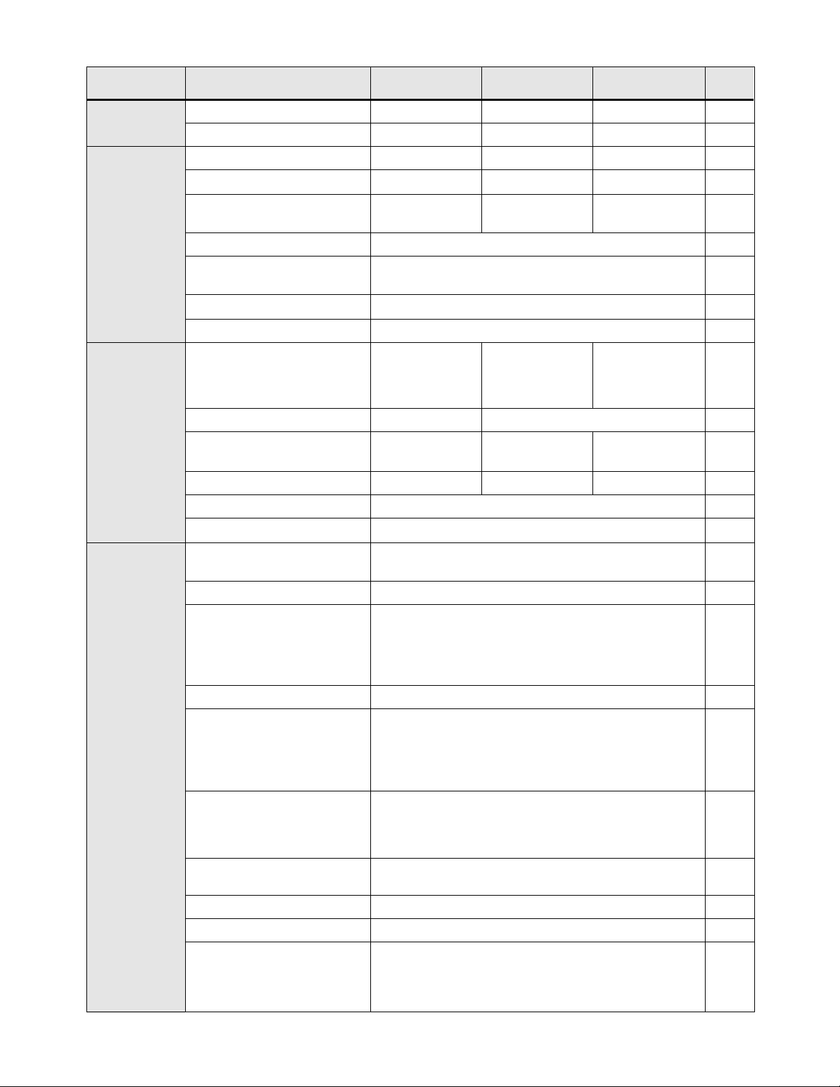
Program Code Summary (Level 1-2)
01 MODEL Model Number 0-65000 Note 1 --- 1 25
02 RVLVL Software Revision 0-640 Note 1 --- 2 25
03 IRAT Rated Current 2-200 Note 1 A 2 25
05 SERNO Serial Number 0-65000 --- --- 2 25
06 REP Repair Date 0-65000 --- --- 2 25
07 FLT3 Last Fault --- --- --- 1 25
08 FLT2 2nd Fault --- --- --- 2 25
09 FLT1 1st Fault --- --- --- 2 25
12 FOUT Output Frequency 0-400 --- Hz 1 25
13 VOUT Output Voltage 0-100 --- % 1 25
14 IOUT Output Current 0-650 --- A 1 26
15 LOAD Drive Load 0-200 --- % 1 26
16 TORQ Load Torque 0-200 --- % 1 26
17 TEMP Inverter Temp 2-105 --- C 1 26
18 TIME1 Total Run Time 0-65000 --- h 2 26
19 TIME2 Power On Hours 0-65000 --- h 2 26
1B FLUX Magnetizing Current 0-100 --- % 2 26
21 MODE Input Mode 0-36 0 --- 1 26&27
24 FSEL Reference Select 0-19 0 --- 2 27
27 TLSEL Torque Limit Select 0-6 0 --- 2 28
31 FMIN Min. Frequency 0.00-400 0 Hz 1 28
32 FMAX Max. Frequency 20.00-400 60 Hz 1 28
33 F2 Preset Speed #2 - Jog 0.00-400 5 Hz 1 28
34 F3 Preset Speed #3 0.00-400 20 Hz 2 28
35 F4 Preset Speed #4 0.00-400 40 Hz 2 28
36 F5 Preset Speed #5 (Note 2) 0.00-400 60 Hz 2 28
37 F6 Preset Speed #6 (Note 2) 0.00-400 0 Hz 2 28
38 F7 Preset Speed #7 (Note 2) 0.00-400 0 Hz 2 28
39 FTL Min. Frequency in Torque Limit 0.00-400 10 Hz 2 29
41 RSEL Ramp Selector 0-7 0 --- 2 29
42 ACC1 Acceleration Time #1 0.10-600 3 s 1 29
43 DEC1 Deceleration Time #1 0.10-600 3 s 1 29
44 ACC2 Acceleration Time #2 0.10-600 1 s 2 29
45 DEC2 Deceleration Time #2 0.10-600 1 s 2 29
46 DECTL Torq. Limit Response Time 0.10-30 1 s 2 29
47 DCBRK DC Brake Time 0-5 0.2 s 2 29
48 DCVLT DC Brake Voltage 0-15 Note 1 % 2 30
51 VSEL V/Hz Characteristic Selector 0-6 0 --- 2 30
52 BOOST Torque Boost 0-25 Note 1 % 1 30
53 FKNEE V/Hz Knee Frequency 26-640 60 Hz 2 31
Name Description Data
Range
Factory
Setting
Units Access
Level See
Page Customer
Setting
#
Artisan Technology Group - Quality Instrumentation ... Guaranteed | (888) 88-SOURCE | www.artisantg.com

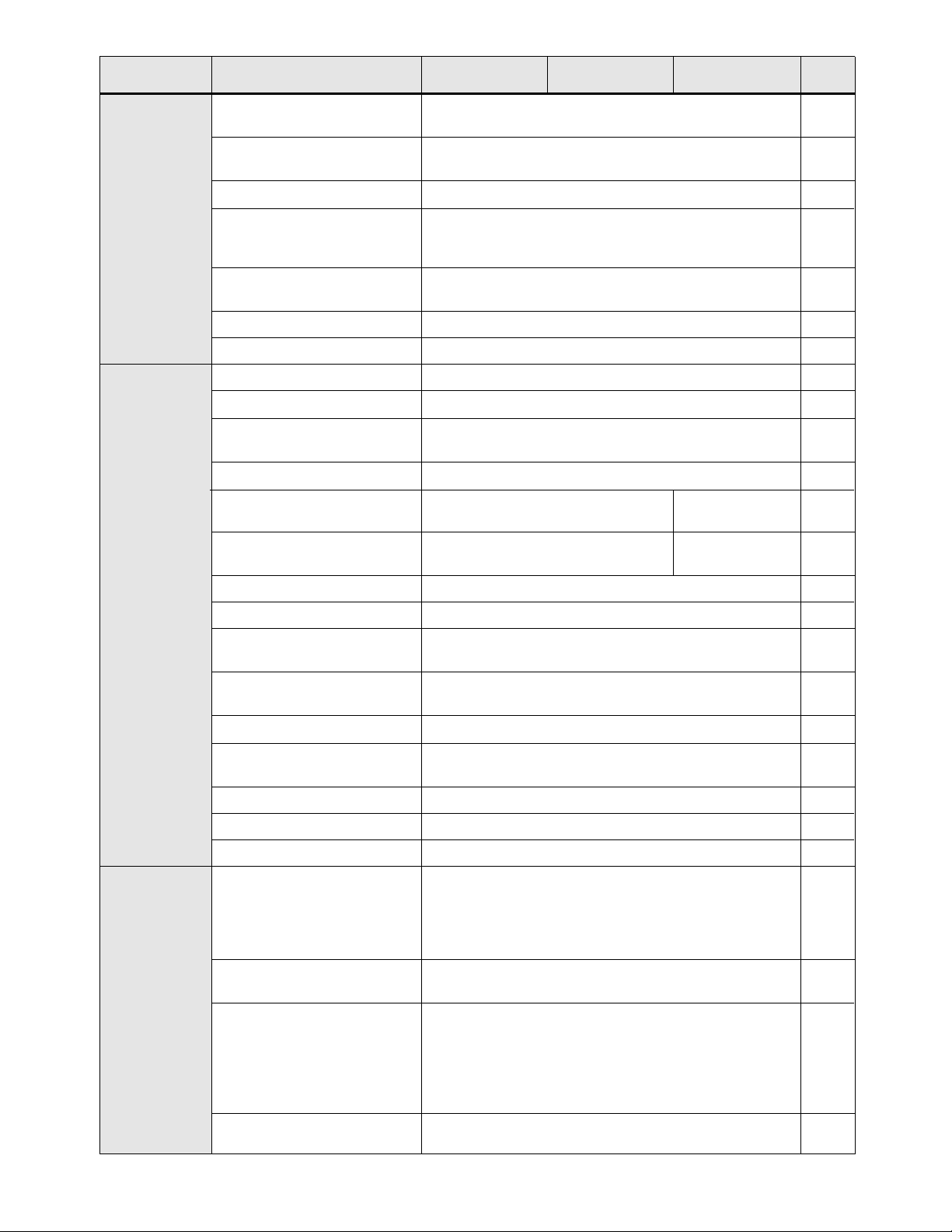
54 SKBND Skip Freq. Hysteresis Band 0.20-20 1 Hz 2 31
55 SK1 Skip Frequency #1 0.00-400 0 Hz 2 31
56 SK2 Skip Frequency #2 0.00-400 0 Hz 2 31
57 SK3 Skip Frequency #3 0.00-400 0 Hz 2 31
58 SK4 Skip Frequency #4 0.00-400 0 Hz 2 31
59 MVOLT Rated Motor Voltage 185-480 Note 1 V 2 31
5B IMAG Rated Magnetizing Current 15-85 Note 1 % 2 31
61 LTLF Load Torque Limit Forward 5-150 150 % 2 31
62 LTLR Load Torque Limit Reverse 5-150 150 % 2 31
63 RTLF Regenerative Torq. Limit FWD 5-110 80 % 2 31
64 RTLR Regenerative Torq. Limit REV 5-110 80 % 2 31
65 SLIP Slip Compensation 0-10 0 % 1 32
66 STAB Current Stability 0-4 2 --- 2 32
67 TOL Timed Overload Trip Point 0-100 0 % 1 32
68 NRST Restart Number 0-8 0 --- 2 33
69 DRST Restart Delay 0-60 0 s 2 33
6A TOLC Timed Overload Characteristic 0-7 0 --- 2 33
70 MCAL Meter Calibration 0-255
Set to 10VDC
--- 1 33
71 METER Analog Meter Output 0-7 1 --- 1 33
72 ST1 Auxiliary Output #1 0-11 6 --- 2 34
73 ST2 Auxiliary Output #2 0-11 3 --- 2 34
74 ST3 Auxiliary Output #3 0-11 7 --- 2 34
75 STR Auxiliary Relay (Fault) 0-11 2 --- 1 34
77 MOL Motor Overload Input 0-1 0 --- 2 34
81 PRGNO Special Program Number 0-65000 0 --- 2 34-39
82 START Inverter Start Options 0-7 0 --- 2 39
83 PWM Carrier Frequency Selector 0-8 1 --- 2 40
84 DISP Display Option Full Setting 0-65000 0 --- 2 42
85 UNITS Display Units ALPHA RPM_1 --- 2 42
86 LANG Display Language 0-3 0 --- 2 43
87 ACODE Security Access Code 0-999 0 --- 2 43
88 FRO Frequency Reference Output 0-1 0 --- 2 43
A2 RATIO Master Slave Speed Ratio (Note 2) 0-200 100 % 2 43
B1 OPTNO Option Board Number 0-6 0 --- 2 43
Cx CNTLx Event Control (1-9)
BINARY (8)
0 --- 2 34-39
Ex ECNTx Event Counts (1-9) 0-65535 0 --- 2 34-39
Name Description Data
Range
Factory
Setting
Units Access
Level See
Page Customer
Setting
#
Notes: 1. Default value is model dependent.
2. Parameter adjustable while drive is in the run mode.
See Section 5 for parameters accessible in Level 3 (SIO control).
See page numbers.
Program Code Summary (Con.’t.)
Artisan Technology Group - Quality Instrumentation ... Guaranteed | (888) 88-SOURCE | www.artisantg.com

TABLE OF CONTENTS Page
Section 1 – General Information
1.1 Preface.......................................................................................................................................... 1
1.2 Inspection...................................................................................................................................... 1
1.3 Control Identification Number........................................................................................................ 1
1.4 Control Specifications ................................................................................................................... 2
1.5 Input/Output Ratings..................................................................................................................... 5
1.6 AC Inverter Fundamentals............................................................................................................ 6
1.7 Description of Operation ............................................................................................................... 6
Section 2 – Installation Instructions
2.1 Rules for Installation...................................................................................................................... 7
2.2 Dimensional Data.......................................................................................................................... 8
2.3 Input AC Line Requirements......................................................................................................... 12
2.4 Inverter Watt Loss......................................................................................................................... 13
2.5 Line Fuse or Circuit Breaker Sizing............................................................................................... 13
2.6 Wiring Practices............................................................................................................................ 13
2.7 Reducing Current Surges.............................................................................................................. 14
2.8 Function and Use of Terminals..................................................................................................... 15
2.9 Environment Considerations......................................................................................................... 17
Section 3 – Setup/Getting Started
3.1 General Information ...................................................................................................................... 18
3.2 Digital Keypad............................................................................................................................... 18
3.3 Operation Mode ............................................................................................................................ 19
3.4 Program Mode .............................................................................................................................. 20
3.5 Status (LED) Indicators................................................................................................................. 20
3.6 Description of Displays.................................................................................................................. 21
3.7 Operating Tips............................................................................................................................... 23
3.8 Quick-Start – Running the Motor................................................................................................... 23
3.9 High Torque Setup Procedure ...................................................................................................... 24
Section 4 – Level 1/Level 2 Parameters
4.1 Programming................................................................................................................................. 25
4.2 Parameter Descriptions................................................................................................................. 25
Section 5 – Level 3 Parameters
5.1 Program Code Summary .............................................................................................................. 44
5.2 Programming................................................................................................................................. 44
5.3 Parameter Descriptions................................................................................................................. 45
Section 6 – Applications
6.1 Connection Diagrams.................................................................................................................... 50
6.2 Options and Accessories .............................................................................................................. 52
6.3 Application Hints ........................................................................................................................... 53
Section 7 – Troubleshooting
7.1 Fault Codes................................................................................................................................... 54
7.2 Troubleshooting ............................................................................................................................ 55
7.3 Maintenance and Inspection......................................................................................................... 56
7.4 Replacement Parts........................................................................................................................ 57
Section 8 – Appendix A
8.1 Additional Publications.................................................................................................................. 59
8.2 Hassle Free Warranty................................................................................................................... 59
Section 9 – Appendix B – RFI Suppression and WLF Line FIlters
Section 1....................................................................................................................................... 60
Section 2....................................................................................................................................... 61
Section 3....................................................................................................................................... 62
Section 4....................................................................................................................................... 65
Section 5....................................................................................................................................... 66
Section 10 – Appendix C
CE Declaration of Conformity........................................................................................................ 68
Artisan Technology Group - Quality Instrumentation ... Guaranteed | (888) 88-SOURCE | www.artisantg.com

1
SECTION 1
GENERAL INFORMATION
1.1 Preface
This manual contains the specifications, installation instructions, description of operation, and troubleshooting
procedure for the WFCHT Series AC Inverters. Before installing the drive, read this manual carefully to ensure
correct installation and maximum performance. The information contained herein is considered current with
the release of version 4.2 (02-RVLVL) of the drive software.
1.2 Inspection
A. Upon receipt of the product, unpack the AC inverter and carefully inspect for any damage sustained in
transit (depression in the enclosure, damage to parts, missing parts). If damage is apparent, the freight or
express agent should be notified within 15 days of receipt of the product and a request be made that he
make an inspection of the merchandise; then a claim should be filed against the carrier. For UPS shipment
damage, save the box and packing material and notify TB Wood’s Incorporated immediately.
B. Next remove the AC inverter cover, if supplied, and inspect for any loose screws, nuts, or connectors.
C. Read the technical data plate and verify the correct horsepower size for the application and note the input
voltage and current required for the inverter.
D. If the inverter is to be stored for a long period of time, repack the inverter and store in a clean, dry place,
free from direct sunlight or corrosive fumes, and in a location where the ambient temperature will not be
less than -20° C (-4° F) nor more than 60° C (140° F).
1.3 Control Identification Number
A systematic numbering system is used to define all WFCHT models by torque output, input voltage rating,
horsepower rating, and enclosure type. This model number appears both on the shipping carton label and the
technical data label on the enclosure. A model number code is also accessible in the Level 1 programming
mode. (Refer to Section 4.2.)
This control number describes a constant torque, WFCHT
adjustable frequency control in a chassis configuration, rated
7.5 HP, with input voltage of 230 VAC.
The different horsepower ratings available and code for each
rating are as follows:
TABLE 1.3
*Input voltage, output voltage is 230 VAC 3 phase.
WF C 2 007-5 A HT
WFCHT Adjustable Frequency ______________________
Torque-C = Constant _____________________________
Input Volts 1 = 115 VAC ____________________________________
2 = 230 VAC _______
4 = 460 VAC _______
Horsepower 007-5 = 7-1/2 HP (See Table 1.3 below.)_____________________________
Housing – A = Chassis__________________________________________________
B = NEMA 1_______
C = NEMA 4_______
HT = High Torque_______________________ CODE HP 115V* 230V 460V
000-7 3/4 X
001-0 1XXX
002-0 2XX
003-0 3XX
005-0 5XX
007-5 7-1/2 X X
010-0 10 X X
015-0 15 X X
020-0 20 X X
025-0 25 X X
030-0 30 X
040-0 40 X
050-0 50 X
060-0 60 X
075-0 75 X
Artisan Technology Group - Quality Instrumentation ... Guaranteed | (888) 88-SOURCE | www.artisantg.com
2
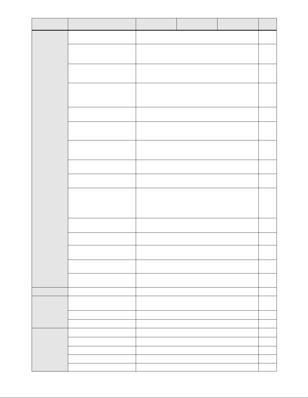
1.4 WFCHT Series Control Specifications
Model Series WFC1000 WFC2000 WFC4000
Horsepower (HP) CT/VT 1 0.75-25 1-75/1-100 5
Kilowatt (kW) 0.75 0.55-19 0.75-56 –
Capacity (kVA) 1.6 1.2-30 1.5-196 5
Continuous Amps 4.0 3-75 2-121 5
Output Voltage 3.5-230 VAC 3Ø3.5-230 VAC 3Ø7.0-460 VAC 3Ø–
(Source limited)
Frequency Range Programmable 0.1-400 Hz 28, 39
Overload Capacity @ 150% for 60 Seconds
40° C Ambient 120% for 90 Seconds 32, 33
Running Torque 150% at 2Hz 30
Efficiency @ Rated Output Greater than 95% –
Input Voltage 115 VAC 1Ø200-230 VAC 1Ø5, 12
(3Øinputs all 3-wire) (FHP-2 HP) 380-460 VAC
200-230 VAC 3Ø3Ø
(3-25 HP)
Voltage Tolerance ±10% -10%; +15% 12
Input Current @ Maximum 9.7 4.8-95 2.2-152.8 5
Rated Output (AC amperes)
KVA @ 50/60 Hz 1.2 1.1-38.1 1.8-122 5
Input Frequency 50/60 Hz ±10% –
Phase Imbalance 2% maximum 12
Control System Sensorless Vector Pulse Width Modulation with
Application Specific Integrated Circuit –
Frequency Range 4000:1, 0.1-400 Hz (Programmable) 28, 31
Frequency Command 0-10 VDC or 0-2 VDC (100 k Ω)
Selections 4-20 mA (237 Ω)
0-1 kHz or 0-10 kHz pulse train 15, 27
Digital Keypad
RS485 Serial Communication Link
Frequency Resolution 0.01 Hz –
Frequency Stability Analog +0.2%
0-1 kHz pulse train +0.4%
0-10 kHz pulse train +0.1% –
Keypad +0.1%
RS485 Port +0.1%
V/Hz Ratio Programmable using FKNEE function
(0.01 Hz resolution)
230 VAC output models – 0.36 to 8.84 31
460 VAC output models – 0.72 to 17.69
Acceleration/Deceleration Programmable – 0.1 to 600 seconds to maximum
Ramps frequency (primary and alternate available) 29
Minimum Frequency Programmable – 0.5 to 400 Hz (0.01 Hz increments) 28
Maximum Frequency Programmable – 20 to 400 Hz (0.01 Hz increments) 28
Torque Limit Four Quadrant Programmable – 5 to 150%
torque (motoring mode); 5 to 110% torque
(regenerative mode) Individual program settings for 28, 31
FWD run, FWD regen, REV run, & REV regen.
See
Page
Applicable
Motor Output
Inverter
Output
Ratings
@ 110%
Motor Ratings
Inverter Input
Ratings
Control
Specifications
TABLE 1.4
Artisan Technology Group - Quality Instrumentation ... Guaranteed | (888) 88-SOURCE | www.artisantg.com
3
Model Series WFC1000 WFC2000 WFC4000
Torque Limit Deceleration Programmable – 0.1 to 30 Seconds 29
Rate
Minimum Frequency in Programmable – 0.5 to 400 Hz 29
Torque Limit
Torque Boost Programmable to suit requirements plus Autoboost 30
Dynamic Braking 30-200% of drive rating (10 sec. max.) standard –
Consult factory for model specific data.
Additional capacity available by adding external DB kits.
Adjustments Over 100 parameters can be monitored with –
over 80 user adjustments
PWM Frequencies Two settings available 39
Agency Listing UL®and cUL®Listed; CE Marked –
Charge Indicator Indicates the presence of potentially lethal bus voltage 15
Ground Fault All models fully protected –
Output Short Circuit All models fully protected –
(Line-to-Line)
Electronic Motor Overload Programmable Inverse Time Overload Trip 32, 33
Overvoltage Trip Level 407 VDC 815 VDC –
(on DC bus)
Undervoltage Trip Level 180 VDC 400 VDC –
(on DC bus)
Torque Limit 4 Quadrant – Independently Programmable 28, 31
Program Lockout User definable security access code 42
Line Start Lockout Prevents automatic startup when line power 39
is applied (defeatable by programming)
Overtemperature Drive will shut down if heat sink temperature –
exceeds rating
DB Failure Drive will sense circuit failure and shut down –
Error/Fault Messages 19 fault codes 53
6 warning displays
Fault Storage Last three (3) faults stored. Most recent displayed. 25
Line Transient Limit 2 KV. Maximum (less than 40 microsecond duration) –
External MOL Contact Compatible with NC fault contact 17
Operating Controls 1. Keypad: Forward, Reverse, Jog, Stop, Program, 18
Shift, Enter, Local/Remote and Up/Down Arrows.
2. Terminal strip: See typical connection 16
diagrams or consult factory.
3. RS485 Serial Input/Output (SIO) Link. 43
LED Indicators Forward, Reverse, Jog, Stop, Bus Charged 20
and CPU Active
Display 2 – lines of 16 characters, Back-Lit
alphanumeric for all modes of operation.
Programmable to display in English, French, 21, 40
Spanish or German.
Any engineering units such as RPM, FPM, &
GPM are supported.
Auxiliary Relay Programmed as Fault Relay. Can be 17, 34
programmed to signal one of eleven conditions
See
Page
Control
Specifications
(continued)
Protection
Features
Operating
Features
TABLE 1.4 (Con’t.)
Artisan Technology Group - Quality Instrumentation ... Guaranteed | (888) 88-SOURCE | www.artisantg.com
4
Model Series WFC1000 WFC2000 WFC4000
Programming Levels Level 1 – Operator Level 2 – Engineer 25, 43
Level 3 – Engineer with SIO
Parameter Block 00 Model #, software revision, rated current, heat –
Drive Data sink temp. trip point, mfg. serial #, repair
date code, & fault log.
Parameter Block 10 Output frequency, voltage, motor current, motor load, –
Status torque, drive temperature, elapsed time since power
applied, & total hours of operation.
Parameter Block 20 Definition of the LOCal/REMote keypad button in –
Control reference to the keypad, terminal strip, & the SIO link.
Also, various speed and torque references are
contained within this block.
Parameter Block 30 Various speed setpoints of the inverter. –
Frequencies
Parameter Block 40 Ramp time selections (the time from start –
Ramps to maximum frequency FMAX or
from FMAX to stop)
Parameter Block 50 V/Hz curves, boost, minimum frequency at –
Voltage/Frequency full voltage, & skip frequencies.
Characteristics
Parameter Block 60 Torque limit setpoints, slip compensation, overload –
Torque Limit trip point, & auto-restart parameters.
Parameter Block 70 METer output, open collector output, & –
I/O Definition fault relay definitions.
Parameter Block 80 Storage & Retrieval of standard or custom programs, –
Program Options complete reset to factory settings, auto-restart, line
start lockout, PWM selection, display of engineering
units, alternate display languages, & customer
access code storage.
Parameter Block 90 BAUD or communication rate, slave address, watch- –
RS485 Serial Link Options dog timer, & retrieval of SIO generated fault codes.
Parameter Block A0 Speed Ratio & various parameters relative to the –
Option Parameters calibration of WPC option cards
Parameter Block B0 Option Board Identification and various parameters –
Option Parameters relative to the calibration of WPC option cards
Parameter Block C0 Used with program sequencer to 35
Event Control Bytes control drive operation
Parameter Block E0 Used with program sequencer to 35
Event Count Bytes control drive operation
Chassis, NEMA 1, NEMA 4 NEMA 4 standard thru 50/60 HP –
Chassis/NEMA 1 In separate enclosure protected from dust, 7
moisture and corrosive fumes.
NEMA 1 Indoor protected from dust, moisture and corrosive fumes 7, 17
NEMA 4 Indoor protected from direct sunlight 7, 17
Operating Temperature Chassis – 0° C to 50° C NEMA 1/4 – 0° C to 40° C –
Storage Temperature -20° C to +60° C –
Humidity 90% RH or less, noncondensing (chassis controls) –
Vibration 0.6 G Maximum –
Elevation Less than 3,300 feet without derating –
See
Page
Programming
Construction
Mounting
Location
Ambient
Conditions
TABLE 1.4 (Con’t.)
Artisan Technology Group - Quality Instrumentation ... Guaranteed | (888) 88-SOURCE | www.artisantg.com

5
1.5 WFCHT INPUT/OUTPUT RATINGS
NOTES:
(1) Required data for sizing input wiring.
(2) CT Amps = Value stored in parameter 03-IRAT. Each model is capable of continuous operation at VT amps
rating. Required data for sizing motor wiring.
(3) For chassis models, ratings are for 1 minute @ +50°C. (40°C external ambient when enclosed.)
(4) Control rated for 110% of motor rating (continuous).
(5) For single phase applications greater than 5 HP, consult factory.
(6) Motor thermal overload relay rating – 1.1 x continuous motor nameplate amps. (Necessary only in multi-
motor applications.)
(7) If the KVA rating of the power source exceeds ten times this value, the use of an isolation transformer or a
line inductor is recommended.
WFC
HT
RATINGS BY MODEL NUMBERS
INPUT RATINGS MAXIMUM MOTOR RATINGS
CONTINUOUS
KVA
(7) AMP
(1) KVA CT.
AMPS (2) VT.
AMPS (2) KVA AMPS
Control
Model
Number
WFCHT
HP
CT/VT
Ø
(5) CONTINUOUS 1 MIN @ 40° C (3)
TABLE 1.5
1001-0 1/1 1 1.6 13.9 1.4 3.6 4.0 2.1 5.4
2000-7 0.75/0.75 1 1.4 6.1 1.1 2.8 3.1 1.7 4.2
2001-0 1/1 1 1.6 7.1 1.4 3.6 4.0 2.1 5.4
2002-0 2/2 1 3.3 14.4 2.7 6.8 7.5 4.1 10.2
2003-0 3/3 3 4.2 10.4 3.8 9.6 10.6 5.7 14.4
2005-0 5/5 3 7.0 17.6 6.1 15.2 16.7 9.1 22.8
2007-5 7.5/7.5 3 10.7 26.9 8.8 22.0 24.2 13.2 33.0
2010-0 10/10 3 13.6 34.2 11.2 28.0 30.8 16.8 42.0
2015-0 15/15 3 21.6 54.3 16.7 42.0 46.2 25.0 63.0
2020-0 20/20 3 27.2 68.2 21.5 54.0 59.4 32.3 81.0
2025-0 25/25 3 34.7 86.9 27.1 68.0 74.8 40.6 102.0
4001-0 1/1 3 1.8 2.2 1.6 2.0 2.2 2.4 3.0
4002-0 2/2 3 3.4 4.3 2.9 3.7 4.1 4.4 5.6
4003-0 3/3 3 4.9 6.2 4.4 5.5 6.1 6.6 8.3
4005-0 5/5 3 8.6 10.8 7.2 9.0 9.9 10.8 13.5
4007-5 7.5/10 3 12.8 16.0 10.4 13.0 14.3 15.5 19.5
4010-0 10/15 3 17.7 22.2 14.3 18.0 19.8 21.5 27.0
4015-0 15/20 3 24.7 31.0 19.1 24.0 26.4 28.7 36.0
4020-0 20/25 3 30.2 37.9 23.9 30.0 33.0 35.9 45.0
4025-0 25/30 3 39.7 49.8 31.1 39.0 42.9 46.6 58.5
4030-0 30/40 3 45.3 56.8 35.9 45.0 49.5 53.8 67.5
4040-0 40/50 3 61.4 77.1 48.6 61.0 67.1 72.9 91.5
4050-0 50/60 3 75.5 94.7 59.8 75.0 82.5 89.6 112.5
4060-0 60/75 3 90.0 112.0 71.0 90.0 98.0 106.4 133.5
4075-0 75/100 3 111.0 134.0 88.0 110.0 121.0 131.5 165.0
Artisan Technology Group - Quality Instrumentation ... Guaranteed | (888) 88-SOURCE | www.artisantg.com
6
1.6 AC Inverter Fundamentals
The principle of operation of the WFCHT, or any AC inverter, is to provide both an adjustable voltage and an
adjustable frequency to the AC motor. The WFCHT automatically maintains the required volts/hertz ratio,
allowing the AC motor to run at its optimum efficiency and providing rated torque capability throughout the
motor’s speed range. The basic formula that relates the output frequency to motor speed is:
Ns = 120 x f Ns = Synchronous Speed (RPM)
P f = Frequency (Hertz)
P = Number of Poles in Motor
For Induction Motors:
Motor RPM = Synchronous Speed – Motor Slip (RPM)
The number of poles of a particular motor, and the amount of slip for a given load torque, are set by the
motor’s design and manufacturer.
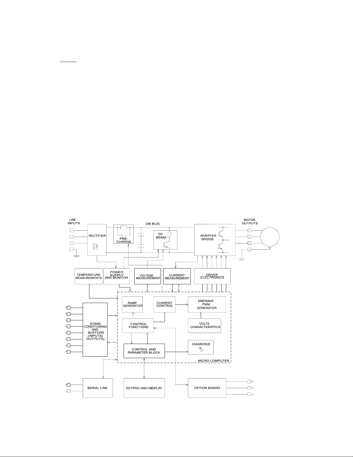
1.7 Description of Operation
The primary functional blocks of the inverter are outlined in Figure 1.7.
The ultimate goal of any inverter is to accept fixed voltage and frequency from a power source and convert this
power into variable voltage and frequency to control a three phase AC induction motor. The WFCHT does this
and much more. It allows the user to interface into the very powerful electronics necessary to provide variable
speed control of the motor, in a very friendly fashion.
Signals can be introduced to the terminal strip for full or partial control of the inverter. The powerful serial input
output (SIO) link is available for total communication and programming. The keypad provides total control of
programming and drive operation.
FIGURE 1.7
Artisan Technology Group - Quality Instrumentation ... Guaranteed | (888) 88-SOURCE | www.artisantg.com

7
SECTION 2
INSTALLATION AND ENCLOSURE DIMENSIONS
2.1 General Rules for Installation
Improper installation of the inverter will greatly affect its life. Be sure to observe the following points when
selecting a mounting location.
A. Do not install the inverter in a place subjected to high temperature, high humidity, or excessive vibration.
(Consult Table 1.4 for temperature, humidity and maximum vibration limits.)
B. Mount the unit vertically and do not restrict the airflow to the heat sink fins on the back of the control. The
fan and fins allow cooling of internal components. Any air restriction could greatly reduce the life of the
inverter, as well as resulting in nuisance over temperature trips.
C. The WFCHT generates heat. Allow sufficient space around the unit, as shown in the illustration. If mounted
in an enclosure with other equipment, be sure to allow at least five (5) inches of space on each side for
adequate ventilation.
D. For totally-enclosed chassis models (fins inside the enclo-
sure), consult TB Wood’s Incorporated for enclosure sizing
and mounting instructions.
E. Do not mount the WFCHT near heat generating equipment or
in direct sunlight.
F. Explosion proof Applications – Part of the criteria for an
explosion proof rating is that the motor is designed and
tested to ensure that its outer surface temperature does not
exceed prescribed levels. These limits can be easily
exceeded if the motor is operated from an AC inverter. A few
manufacturers of explosion proof motors have received UL®
certification for their products when used on AC inverters.
These motors have very strict operating speed limits and
other disclaimers to protect the companies in case an
accident occurs involving their product. Explosion proof
motors that are not rated for inverter use lose their
certification when used for variable speed. Due to the many
areas of liability that may be encountered when dealing with
these applications, the following statement of Company
Policy applies:
TB Wood’s Incorporated AC Inverter products are sold for suitability with explosion proof AC motors rated
for use with PWM inverters. These motors must be UL listed for use with either TB Wood’s AC inverters or
with PWM inverters and used within the specified speed ranges and carrier frequencies. TB Wood’s
accepts no responsibility for any direct, incidental or consequential loss, cost or damage associated with
the misapplication of our AC products in these applications. In any misapplication, the purchaser expressly
agrees to assume all risk of loss, cost or damage that may arise. TB Wood’s Incorporated will not
knowingly approve the application of their AC inverters with motors not rated for such applications.
G. Line Starting – WFCHT is designed to provide controlled starting and stopping of AC motors by use of the
keypad or external contacts connected to the control terminal strip. WFCHT may also be started by applying
AC power to terminals L1, L2, and L3. The inverter has line-start-lockout as a standard feature, to prevent
automatic starting when line power is applied. This provision can be defeated by appropriate programming.
The inverter may be started once every two minutes in this mode.
H. Chassis Model Installation -- The Chassis style WFCHT series is shipped with the keypad attached to the
inverter, but it can be removed and attached to an enclosure front cover or remote station (See Section
6.2). Note: CE specifications require that any system component housed within an enclosure,
cannot have an attached operator control. Therefore, the keypad must be removed from the
inverter and attached to an enclosure panel to maintain CE compliance in these cases.
FIGURE 2.1
MORE
THAN
5 IN.
MORE
THAN
5 IN.
MORE
THAN
5 IN.
MORE
THAN
5 IN.
®
WFC
HT AC
INVERTER
Artisan Technology Group - Quality Instrumentation ... Guaranteed | (888) 88-SOURCE | www.artisantg.com
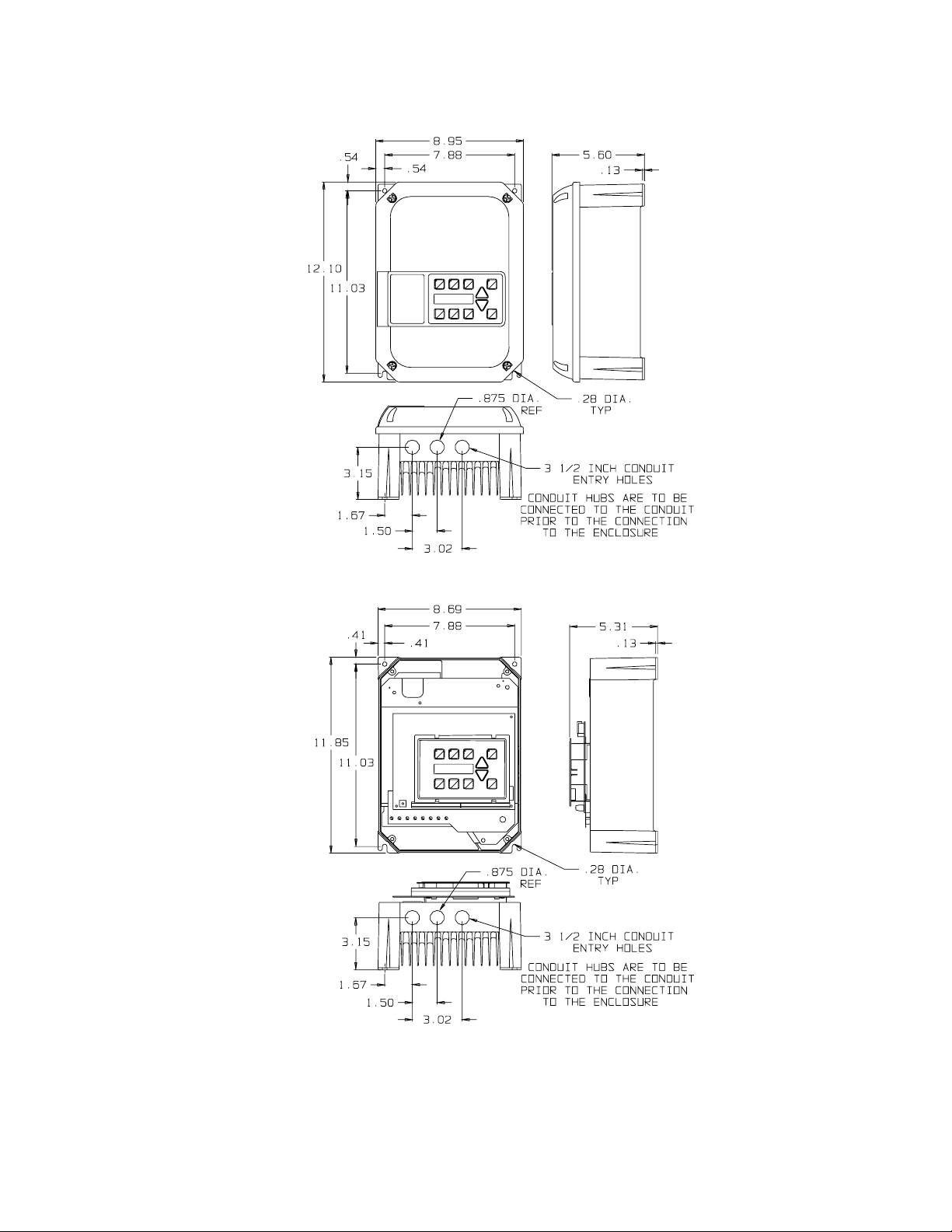
8
2.2 Dimensional Data
The following pages show the dimensional data for the NEMA 4 and chassis style WFCHT Inverters. Use this
data and the General Rules for Installation to select a suitable mounting location.
FHP-5 HP
NEMA 4 & CHASSIS MODELS
FIGURE 2.2
Artisan Technology Group - Quality Instrumentation ... Guaranteed | (888) 88-SOURCE | www.artisantg.com
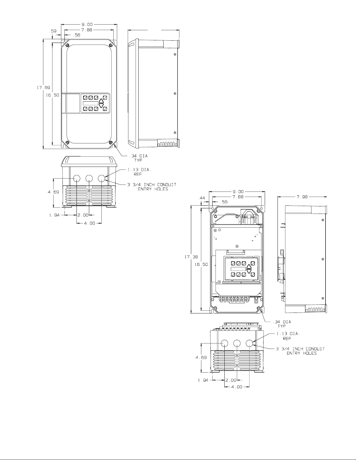
9
7.5-10 HP 230 VAC
7.5-20 HP 460 VAC
NEMA 4 & CHASSIS MODELS
FIGURE 2.3
8.33
Artisan Technology Group - Quality Instrumentation ... Guaranteed | (888) 88-SOURCE | www.artisantg.com

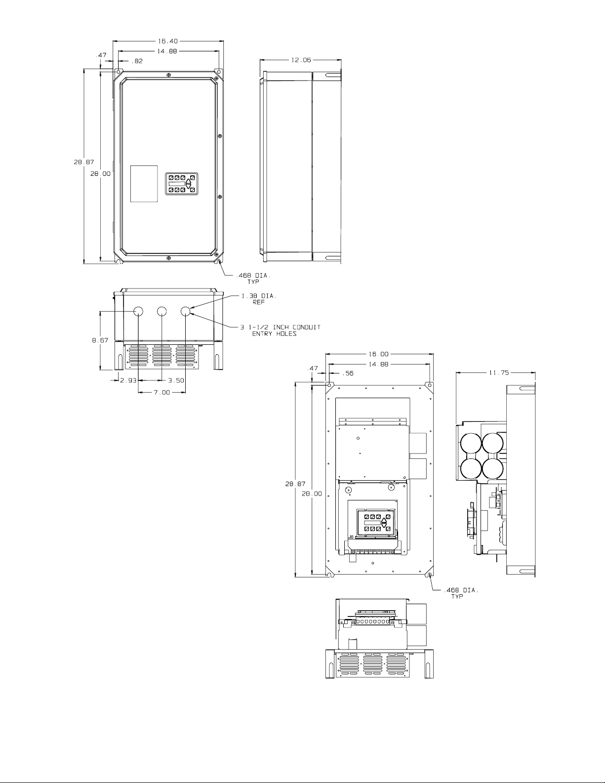
10
15-20 HP 230 VAC
25-30 HP 460 VAC
NEMA 4 & CHASSIS MODELS
FIGURE 2.4
Artisan Technology Group - Quality Instrumentation ... Guaranteed | (888) 88-SOURCE | www.artisantg.com
11
25 HP 230 VAC
40-75 HP 460 VAC (NEMA 1/NEMA 4 MODELS)
40-75 HP 460 VAC (CHASSIS MODELS)
FIGURE 2.5
Artisan Technology Group - Quality Instrumentation ... Guaranteed | (888) 88-SOURCE | www.artisantg.com

2.3 Input AC Line Requirements
The allowable AC line voltage fluctuation is -10% to +15% of nominal line voltage. A supply voltage above or
below these limits could cause the inverter to trip out with either an overvoltage or an undervoltage fault.
NOTE:
Caution must
be exercised
when applying
WFCHT Invert-
ers on low line
conditions.
For example, a WFC2000 Series Inverter will operate properly on a 208 VAC line. However, the maximum
output voltage will be limited to 208 VAC. If the motor is rated for 230 VAC line voltage, higher motor currents
and increased heating will result. Ensure that the voltage rating of the motor matches the applied line
voltage.
If other than 60 Hz output can be tolerated, proper volts/hertz can be programmed into the inverter by the 53-
FKNEE and 32-FMAX parameters. If you are unsure about this feature, consult Section 4.2 or the factory.
Phase voltage imbalance of the input AC source can cause unbalanced currents and excessive heat in the
input rectifier diodes and in the DC bus capacitors of the WFCHT. Phase imbalance is calculated by the
following method:
Assume: The voltage from L1 to L2 = La
The voltage from L2 to L3 = Lb
The voltage from L1 to L3 = Lc
The average line voltage = Lavg
Determine the absolute value of the difference between each of the line voltages (La, Lb, & Lc) and Lavg.
(Subtract the two values and disregard the sign of the result.) Consider the results of this calculation to be
Laa, Lba, & Lca.
Phase Imbalance (%) = Laa + Lba + Lca x 100%
2 (Lavg)
Example:
Measured phase voltages of 230, 235, & 240 would result in a calculated phase imbalance of 2.1%.
If the resulting phase imbalance exceeds 2%, consult your local power company or plant maintenance
personnel and ask them to investigate this problem and recommend methods of correcting this condition.
Phase imbalance can be damaging to motors running Across-the-Line also. A 2% imbalance requires a 5%
derating factor on the motor, 3% imbalance requires a 10% derating, 4% requires an 18% derating.
CAUTION: NEVER USE POWER-FACTOR IMPROVEMENT CAPACITORS ON THE WFCHT MOTOR
TERMINALS, M1, M2, AND M3, OR DAMAGE TO THE INVERTER’S SEMICONDUCTORS WILL RESULT.
A. Single Phase Operation
Certain models of WFCHT series AC inverters are designed for single phase input. The output is still 230
VAC, three phase; therefore, do not connect single-phase motors to the inverter’s output terminals
as damage may occur.
Models WFC1001-0 (115 VAC), WFC2000-7 (230 VAC), WFC2001-0, and WFC2002-0 are designed
specifically for single phase input. For other requirements, please contact the factory.
B. Line Starting
WFCHT is designed to provide controlled starting and stopping of AC motors by use of the keypad or
external contacts connected to the control terminal strip. WFCHT may also be started by applying AC power
to terminals L1, L2, and L3. The inverter has line-start-lockout as a standard feature, to prevent automatic
starting when line power is applied. This provision can be defeated by appropriate programming. The
inverter may be started once every two minutes in this mode.
12
WARNING
DISCONNECT POWER BEFORE SERVICING THIS CONTROL.
HAZARDOUS VOLTAGES EXIST UNTIL CHARGE LIGHT GOES OUT.
AVERTISSEMENT
COUPER L’ALIMENTATION AVANT D’ENRERENORE LE DEPANNAGE DU SYSTEME ELECTRIQUE.
VOLTAGE DANGEUREUX EXISTE TANT QUE LA LUMIERE INDICATRICE RESTE ALLUMÉ.
Input Power Transformer Rating
Lavg = La + Lb + Lc
3
Rated HP FHP 1 2 3 5 7-1/2 10 15 20 25 30 40 50 60 75
Minimum 2 2 4 5 9 13 18 25 31 40 46 62 76 90 112
KVA Rating
Artisan Technology Group - Quality Instrumentation ... Guaranteed | (888) 88-SOURCE | www.artisantg.com
This manual suits for next models
2
Table of contents


