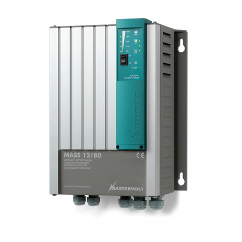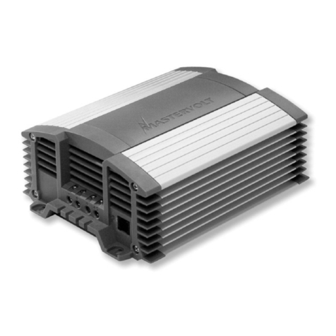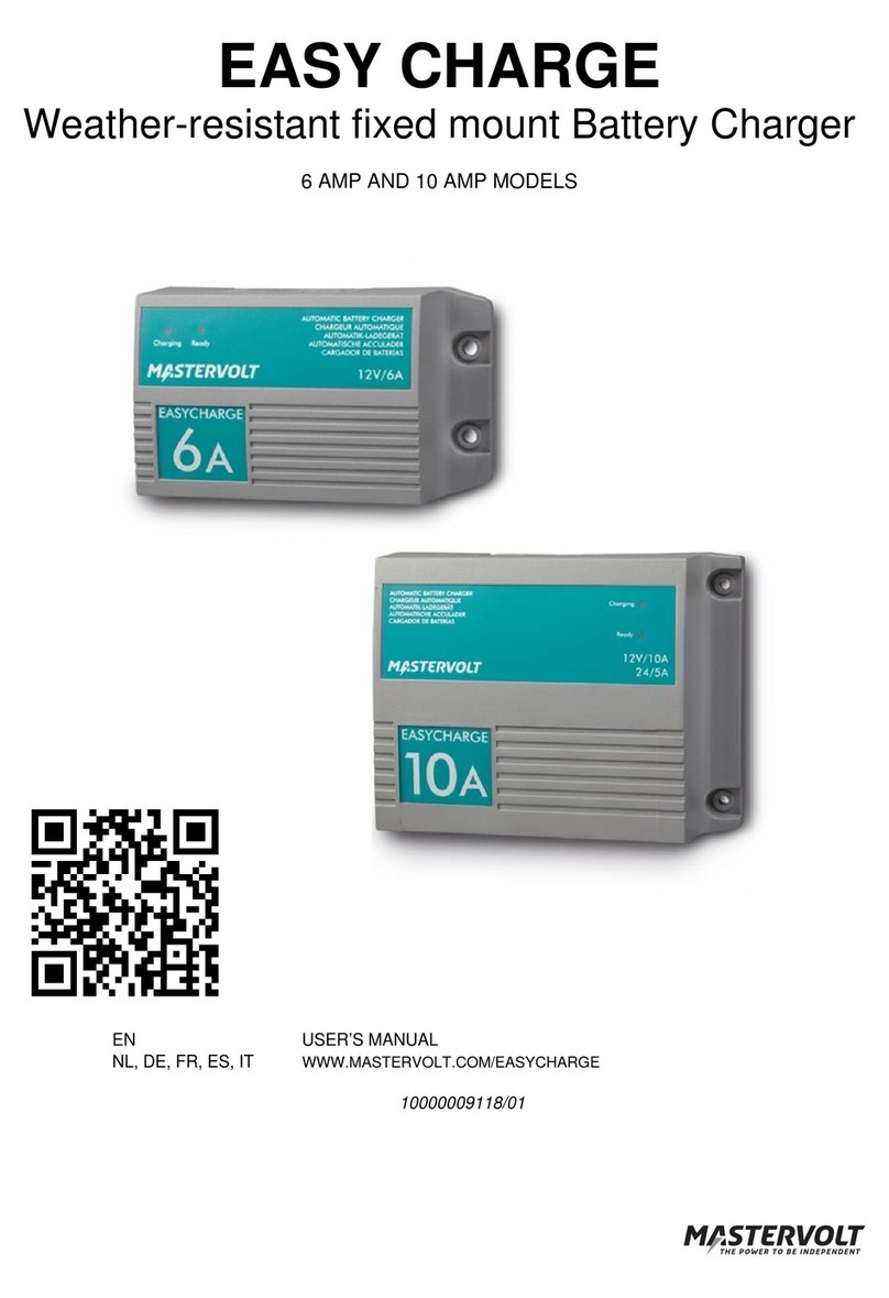
– User and Installation Manual
TABLE OF CONTENTS
1SAFETY INSTRUCTIONS ............................................ 3
1.1 General ................................................... 3
1.2 Warnings regarding the use of batteries .. 4
1.3 Location................................................... 5
1.4 Connections ............................................ 5
1.5 Warning regarding life support
applications ............................................. 5
2GENERAL INFORMATION .......................................... 6
2.1 Liability .................................................... 6
2.2 Warranty.................................................. 6
2.3 Identification label.................................... 6
2.4 Correct disposal of this product ............... 6
3PRODUCT DESCRIPTION........................................... 7
3.1 Overview of the connections.................... 7
3.1.1 Models 1500W, 2000W, 3000W............ 7
3.1.2 Models 3500W, 4500W, 5000W............ 8
3.2 Operating modes..................................... 8
3.3 Protection .............................................. 10
4INSTALLATION.......................................................... 11
4.1 Unpacking ............................................. 11
4.2 Location................................................. 11
4.3 Batteries ................................................ 12
4.4 Connection examples ............................ 13
4.4.1 Models 1500W, 2000W, 3000W.......... 13
4.4.2 Models 3500W, 4500W, 5000W.......... 14
4.5 Wiring.................................................... 15
4.5.1 DC wiring ............................................ 15
4.5.2 AC wiring............................................. 16
4.5.3 AC safety grounding............................ 17
4.5.4 Network wiring (CZone/MasterBus)..... 18
4.6 Tools and materials needed .................. 19
4.7 Installation step-by-step......................... 20
4.8 Accessories connector (dry contacts) .... 23
4.8.1 Remote switch..................................... 24
4.8.2 Output ................................................. 24
5SETTINGS .................................................................. 25
5.1 DIP switch settings ................................ 25
5.2 MasterBus configuration........................ 26
5.2.1 Monitoring tab ..................................... 26
5.2.2 Alarms tab........................................... 28
5.2.3 History tab........................................... 28
5.2.4 Configuration tab................................. 28
5.2.5 Events tab – System automation......... 31
5.3 CZone configuration .............................. 32
6OPERATION...............................................................34
6.1 Switching on / charge only .....................34
6.2 Status LEDs...........................................34
6.3 Remote control.......................................35
6.4 3-step+ charge process..........................35
6.5 Temperature compensated charging......36
6.6 Reset the thermal breaker after an
overload .................................................36
6.7 Maintenance ..........................................37
6.7.1 Decommissioning ................................37
6.7.2 Storage and transportation ..................37
7PARALLEL AND SPLIT-PHASE SYSTEMS..............38
7.1 General information................................38
7.2 Materials needed ...................................39
7.3 Preparations ..........................................39
7.4 DC wiring ...............................................40
7.5 AC wiring ...............................................41
7.5.1 AC wiring of single-phase parallel
units.....................................................42
7.5.2 AC wiring of split-phase units (one unit
for each phase)....................................43
7.5.3 AC wiring of split-phase (two parallel
units for each phase) ...........................45
7.6 Network wiring .......................................46
7.6.1 Preparation ..........................................46
7.6.2 Network wiring of single-phase parallel
units.....................................................47
7.6.3 Network wiring of split-phase units.......47
7.6.4 Network wiring of two units in split-phase
with two units in parallel.......................48
7.7 Configuration and initial start-up.............48
7.7.1 DIP switches (for a single-phase parallel
configuration in a basic MasterBus
system)................................................49
7.7.2 MasterAdjust........................................50
7.7.3 CZone Configuration Tool....................51
7.8 Breaking down a cluster.........................53
8TROUBLESHOOTING................................................ 54
9TECHNICAL DATA.....................................................56
9.1 Inverter specifications ............................56
9.2 Charger specifications............................57
9.3 Transfer system specifications ...............59
9.4 Miscellaneous ........................................60
9.5 CZone specifications..............................60
9.6 Characteristics .......................................61
9.7 Dimensions ............................................62
