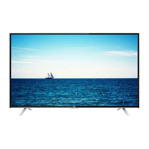
TCL LED39T3510 User manual

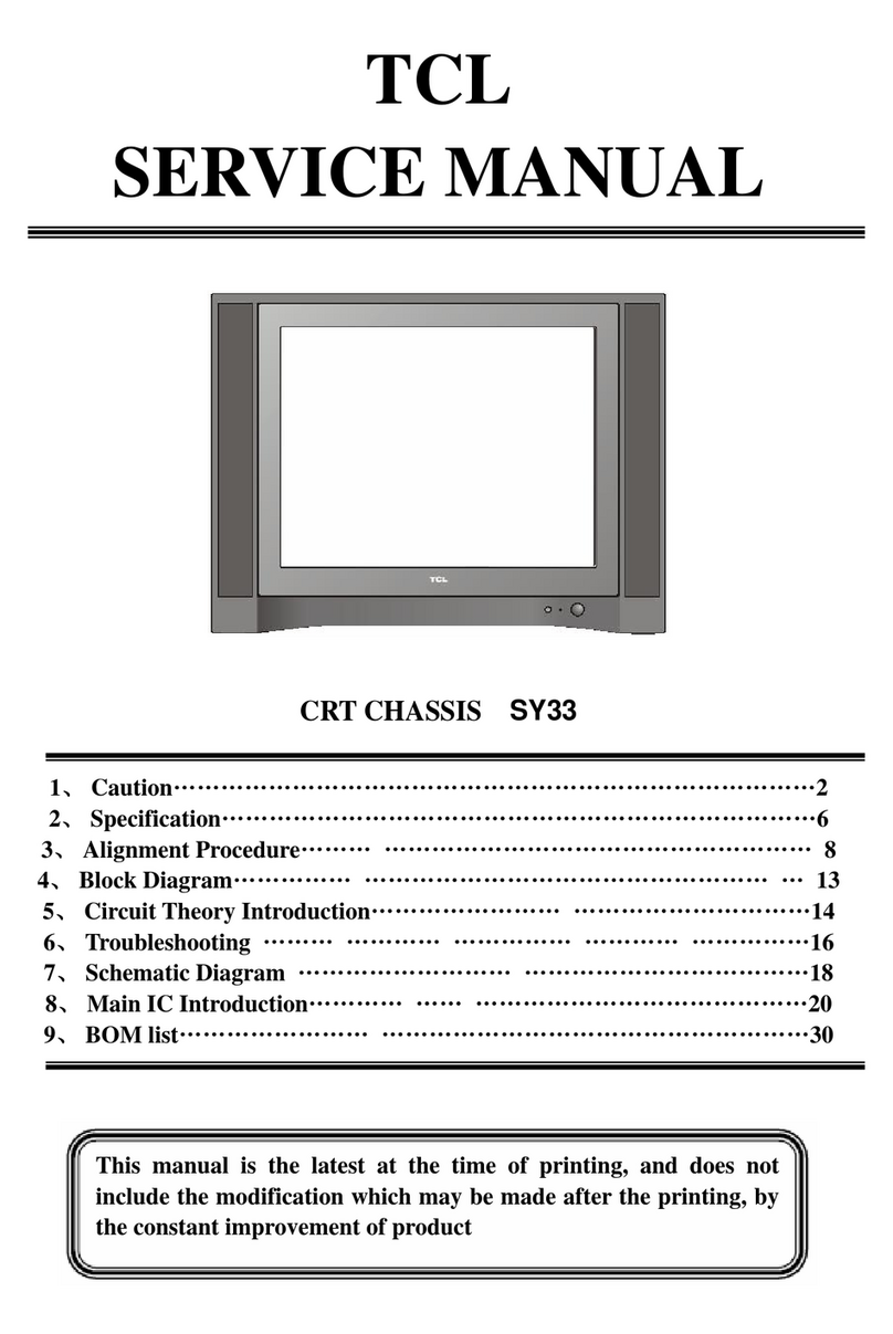
TCL
SERVICE MANUAL
LED39T3510/MS82F-AP
1. Caution…………………………………………………………………………2
2. specification……………………………………………………………………6
3. Alignment Procedure…………………………………………………………7
4.Block diagram…………………………………………………………………1
5.Scheme Diagram ……………………………………………………………
5. Troubleshooting………………………………………………………………26
6. PCB Layout …………………………………………………………………3
([SORGHGUDZLQJ2
8. BOM list..............................................................................................................33
This m anual i s t he l atest at t he t ime of pr inting, and doe s not
include the modification which may be made after the printing, by
the constant improvement of product

CA UTION: TO RE DUCE THE RIS K OF
ELECTR ICA L SHOCK, DO NOT RE MOVE
COVER (OR BACK). NO USER SERVICEABLE
PAR TS INSIDE . RE FE R SER VIC ING TO
QUALIFIED SERVICE PERSONNEL.
The lighting flash with arrowhead symbol, with an equilateral triangle is intended to
alert the user to the presence of uninsulated voltage within the products
enclosure that may be of sufficient magnitude to constitute a risk of electric shock to
the person.
The exclamation point within an equilateral triangle is intended to alert the user to the
presence of important operating and maintenance (servicing) instructions in the
literature accompanying the appliance.
CAUTION:
Use of controls, adjustments or procedures other than those specified herein may result in
hazardous radiation exposure.
CA U T ION
RISK
RISK OF
ELECTRI
ELECTRIC
SHOCK
SHOCK DO
NOT
NOT
OPEN.
OPEN.
2
dangerous
WARNING: TO REDUCE RISK OF FIRE OR ELECTRIC SHOCK, DO NOT
EXPOSE THIS APPLIANCE TO RAIN OR MOISTURE.
SCHNEIDER ELECTRONICS GMBH-GERMANY
1. CAUTION
2

1. When the power cord or plug is damaged or frayed, unplug this television set from the wall outlet and refer servicing to
qualified service personnel.
2. Do not overload wall outlets and extension cords as this can result in fire or electric shock.
3. Do not allow anything to rest on or roll over the power cord, and do not place the TV where power cord is subject to
traffic or abuse. This may result in a shock or fire hazard.
4. Do not attempt to service this television set yourself as opening or removing covers may expose you to dangerous
voltage or other hazards. Refer all servicing to qualified service personnel.
5. Never push objects of any kind into this television set through cabinet slots as they may touch dangerous voltage
points or short out parts that could result in a fire or electric shock. Never spill liquid of any kind on the television set.
6. If the television set has been dropped or the cabinet has been damaged, unplug this television set from the wall outlet
and refer servicing to qualified service personnel.
7. If liquid has been spilled into the television set, unplug this television set from the wall outlet and refer servicing to
qualified service personnel.
8. Do not subject your television set to impact of any kind. Be particularly careful not to damage the picture tube surface.
9. Unplug this television set from the wall outlet before cleaning. Do not use liquid cleaners or aerosol cleaners. Use a
damp cloth for cleaning.
10.1. Do not place this television set on an unstable cart, stand, or table. The television set may fall, causing serious injury
to a child or an adult, and serious damage to the appliance. Use only with a cart or stand recommended by the
manufacturer, or sold with the television set. Wall or shelf mounting should follow the manufacturer s instructions, and
should use a mounting kit approved by the manufacturer.
10.2. An appliance and cart combination should be moved with care. Quick stops, excessive force, and uneven surfaces
may cause the appliance and cart combination to overturn.
CAUTION:
Read all of these instructions. Sa ve these instructions for later use . Follo w all Warnings and
Instructions marked on the audio equipment.
1. Read Instructions-All the safety and operatinginstructionsshouldbe read before the productis operated.
2. Retain Instructions- The safety and operating instructions should be retained for future reference.
3. Heed Warnings- All warnings on the product and in the operating instructions should be adhered to.
4. Follow Instructions- All operating and use instructions should be followed.
3
SCHNEIDER ELECTRONICS GMBH-GERMANY
IMPORTANT SAFETY INSTRUCTIONS
FOR YOUR PERSONAL SAFETY
3

11. Do not use this television set near water ... for example, near a bathtub, washbowl, kitchen sink, or laundry tub, in a
wet basement, or near a swimming pool, etc.
Never expose the set to rain or water. If the set has been exposed to rain or water, unplug the set from the wall
outlet and refer servicing to qualified service personnel.
12. Choose a place where light (artificial or sunlight) does not shine directly on the screen.
13. Avoid dusty places, since piling up of dust inside TV chassis may cause failure of the set when high humidity persists.
14. The set has slots, or openings in the cabinet for ventilation purposes, to provide reliable operation of the receiver, to
protect it from overheating. These openings must not be blocked or covered.
Never cover the slots or openings with cloth or other material.
Never block the bottom ventilation slots of the set by placing it on a bed, sofa, rug, etc.
Never place the set near or over a radiator or heat register.
Never place the set in enclosure, unless proper ventilation is provided.
15.1. If an outside antenna is connected to the television set, be sure the antenna system is grounded so as to provide some
protection against voltage surges and built up static charges, Section 810 of the National Electrical Code, NFPA No.
70-1975, provides information with respect to proper grounding of the mast and supporting structure, grounding of the
lead-in wire to an antenna discharge unit, size of grounding conductors, location of antenna discharge unit, connection
to grounding electrode, and requirements for the grounding electrode.
15.2. Note to CATV system installer : (Only for the television set with CATV reception)
This reminder is provided to call the CATV system attention to Article 820-40 of the NEC that provides
guidelines for proper grounding and, in particular, specifies that the cable ground shall be connected to the grounding
system of the building, as close to the point of cable entry as practical.
16. An outside antenna system should not be located in the vicinity of overhead power lines or other electric lights or power
circuits, or where it can fall into such power lines or circuits. When installing an outside antenna system, extreme care
should be taken to keep from touching such power lines or circuits as contact with them might be fatal.
17. For added protection for this television set during a lightning storm, or when it is left unattended and unused for long
periods of time, unplug it from the wall outlet and disconnect the antenna. This will prevent damage due to lightning
and power-line surges.
ANTENNA
LEAD- IN WIRE
ANTENNA DISCHARGE
UNIT (NEC SECTION
810-20)
GROUNDING
CONDUCTORS
(NEC SECTION810-21)
GROUND CLAMPS
POWER SERVICE GROUNDING
ELECTRODE SYSTEM
(NEC ART 250. PART H)
ELECTRIC SERVICE
EQUIPMENT
GROUND CLAMP
NEC-NATIONAL ELECTRICAL CODE
EXAMPLE OF ANTENNA GROUNDING AS PER
NATIONAL ELECTRICAL CODE
EXAMPLE OF ANTENNA GROUNDING AS PER NATIONAL ELECTRICAL CODE INSTRUCTIONS
a built-in
installer s
4
SCHNEIDER ELECTRONICS GMBH-GERMANY
PROTECTION AND LOCATION OF YOUR SET
4

18.
This television set should be operated only from the type of power source indicated on the marking label.If you are not
sure of the type of power supply at your home, consult your television dealer or local power company. For television
sets designed to operate from battery power, refer to the operating instructions.
19. If the television set does not operate normally by following the operating instructions, unplug this television set from the
wall outlet and refer servicing to qualified service personnel. Adjust only those controls that are covered in the operating
instructions as improper adjustment of other controls may result in damage and will often require extensive work by a
qualified technician to restore the television set to normal operation.
20. When going on a holiday : If your television set is to remain unused for a period of time, for instance, when you go on
a holiday, turn the television set and unplug the television set from the wall outlet.
21. If you are unable to restore normal operation by following the detailedprocedurein your operatinginstructions,
do not attempt any further adjustment. Unplug the set and call your dealer or service technician.
22. Whenever the television set is damaged or fails, or a distinct change in performance indicates a need for
service, unplug the set and have it checked by a professional service technician.
23. It is normal for some TV sets to make occasional snapping or popping sounds, particularly when being
turned on or off. If the snapping or popping is continuous or frequent, unplug the set and consult your
dealer or service technician.
24. Do not use attachments not recommendedby the television set manufacturer as they may cause hazards.
25. When replacementparts are required, be sure the service technicianhas used replacementparts specified
by the manufacturer that have the same characteristics as the original part. Unauthorized substitutions
may result in fire, electric shock, or other hazards.
26. Upon completion of any service or repairs to the television set, ask the service technician to perform
routine safety checks to determine that the television is in safe operating condition.
off
5
SCHNEIDER ELECTRONICS GMBH-GERMANY
OPERATION OF YOUR SET
IF THE SET DOES NOT OPERATE PROPERLY
FOR SERVICE AND MODIFICATION
5

第1页共 11 页
OEM 事业部
OEM 设计中心
Alignment Procedure
(MODEL):MS82) Series
VERSION:V1.0
PREPAREDBY: Xiongzp DATE : 2012-12-25
APPROVEDBY: DATE:
文件编号:CRT/SJ/FK02-2010
序号:

第2页共 11 页
History Description of major changes Release Date
V1.0 2012-12-25
1.Overview
MS82L chassis is designed for Asia Pacific/South America market. Both
Full HD panel and HD panel can be compatible. The signal sources include
TV,AV,YPBPR/YCBCR,VGA,HDMI and USB. For YPBPR,HDMI source ,Format up to
1080p can be supported; USB support image, audio and video(up to
H.264)playing; The whole process of alignment includes ADC calibration
and White Balance adjustments.
2.Factory Menu
1、Methods of Entering
Method 1:Using the remote ,enter the “Picture” submenu in the OSD;
choosing the “contrast” item and press the 9,7,3 and 5 in series,
Factory Menu will appear in the left top of screen
Method 2:Press RETURN button when FACTORY HOTKEY is enabled(ON).
2. General introduction
FACTORY MENU
ITEMS Default
Setting
Description Status
1-FAC HOTKEY OFF Factory hotkey Switch
(OFF/ON).Should be OFF after factory
alignment
OK
2-WARM UP OFF OFF:The set would enter standby mode
after 15 minutes without input
signal;
ON : Aging mode. Aging time will
display on the left bottom of screen.
OK
3-ADC ADC calibration(refer as follow) OK
4-WHITE BALANCE White Balance data adjustment(refer
as follow)
The balance data is set by PE before
the mass production. Do not need
adjust.
OK

第3页共 11 页
5-SHOP DO Reset the set after production
alignment;(This operation will
remove all unnecessary factory value;
The factory hotkey will be turn off)
OK
6-NVM reset DO System initialization. Restore all
data except the White Balance and ADC
data ;Only for R&D.
OK
7-SET FAC CH DO Preset specific factory channels for
specific factory. Press left and
right button to select the factory,
and then press OK to confirm.
OK
8-POWER ON
LAST ON: Always turns on TV when AC power
on
STB:Always goes to standby mode when
AC power on
LAST:Restore the status before the
last AC power off
OK
9-USB UPDATE USB update,(refer as follow) OK
10
ReloadEFBItem…
This item only factory used, OK
Note: Below the factory menu, some model information are showed, including
software version, Project Name, SIACP Version, and SW release time.
ADC Submenu:
ITEMS Default
Setting
Description Status
Source RGB/YPbP
r
(HD)
Sources need calibration. RGB means PC and
YPbPr(HD) means YPbPr
OK
R-GAIN 4478 R-GAIN OK
G-GAIN 4478 R-GAIN OK
B-GAIN 4478 R-GAIN OK
R-OFFSET 2048 B-OFFSET OK
G-OFFSET 2048 B-OFFSET OK
B-OFFSET 2048 B-OFFSET OK
AUTO ADC WAIT/OK With appropriate pattern (mentioned below)
inputted, press left or right key to start auto
calibration.
OK
WHITE BALANCE Submenu

第4页共 11 页
ITEMS Default
Setting
Description Statu
s
Source Current
Source
Current Source( TV,AV1/AV2/YPbPr, HDMI need
adjustment)
OK
COLOR TEMP NORMAL NORMAL/COOL/WARM OK
R-GAIN 128 R-GAIN OK
G-GAIN 128 G-GAIN OK
B-GAIN 128 B-GAIN OK
R-OFFSET 128 R-OFFSET OK
G-OFFSET 128 G-OFFSET OK
B-OFFSET 128 B-OFFSET OK
WB INIT DO ONLY FOR TCL R&D OK
The first step is to adjust HDMI.
3.Design Menu
1、Methods of Entering:
Method 1:Using the remote, enter the “Picture” submenu in the OSD; choosing
the “contrast” item and press the 1,9,5,and 0 in series ,Design Menu will
appear in the left top of screen.
Method 2: Press RETURN button when DESIGN HOTKEY is enabled (ON).
2、General introduction
DESIGN MENU
ITEMS Default
Setting
Description Status
1-DESIGN
HOTKEY
OFF ON/OFF OK
2-FACTORY
MENU
ON/OFF OK
3-SHOP INIT Default setting submenu after production
alignment refer to **
OK
4-OTHER Other set .Only for TCL R&D OK

第5页共 11 页
5-SERVICE
MENU
After service menu description OK
6-PARAM
SETTING
Parameter setting submenu OK
7-HOTEL
MENU
Hotel submenu OK
8,LANGUAGE
MENU
OSD 语言设定
SHOP INIT submenu
ITEMS Default
Setting
Description Status
Volume 30 0-100 adjustable OK
PIC MODE STANDARD STANDARD/BRIGHT/SOFT/PERSONAL OK
SOUND MODE STEREO STEREO/MUSIC/MOVIE/NEWS OK
Channel 199 0-199 adjustable OK
Language English Up to 7 languages optional OK
COLOR SYS AUTO AUTO、PAL、 NTSC、SECAM OK
SOUND SYS DK DK、BG、I、M OK
PRESET CH 1 0-199 adjustable OK
COLOR TEMP NORMAL NORMAL、WARM、COOL OK
Other
ITEMS Default
Setting
Description Status
VIF1 VIF adjust OK
VIF2 VIF adjust OK
VIF3 VIF adjust OK
QMAP
ADJUST
PQ debug OK

第6页共 11 页
SSC SSC adjust OK
DBC ENABLE DBC adjust OK
BP OK
CP OK
DBC MODE OK
MIU DQS0
MIU DQS1
TELETEXT ON TELETEXT SWITCH (only for MS82B/E series) OK
NICAM ON NICAM SWITCH (only for MS82B/E series) OK
PARAM SET SETTING
ITEMS Default
Setting
Description Status
Brightness
Curve Brightness curve. Exclusively used by R&D OK
Contrast
Curve Contrast curve. Exclusively used by R&D OK
Saturation
Curve Saturation curve. Exclusively used by R&D OK
Hue Curve Hue curve. Exclusively used by R&D OK
Sharpness
Curve Sharpness curve. Exclusively used by R&D OK
Volume Curve Volume curve. Exclusively used by R&D OK
BackLight
Curve BackLight curve. Exclusively used by R&D OK
OverScan Exclusively used by R&D
4、Service Menu
1、Methods of Entering
Using the remote, enter the “Picture” submenu in the OSD; choosing the
“contrast” item and press the 9,7,0 and 5 in series, Service Menu will appear in
the left top of screen
SERVICE MENU:
ITEM Defau
lt
Setti
ng
Description Status
SW NO Software Version OK

第7页共 11 页
DATE Date and time of software releasing OK
Project Name Module name OK
SIACP VERSION SIACP VERSION OK
Chassis MS82V
G
Chassis name OK
PANEL NAME P/N of panel OK
NG
PROJECT ID Project Select submenu OK
CONFIG Project Select submenu
USB UPDATE USB UPDATE ok
HOTEL ENABLE
OFF
HOTEL MENU SWITCH ok
ReloadEFBItem Do Only for factory adjust OK
CONFIG submenu
ITEM Default
Setting
Description Status
PWON_MUSIC OFF Power on music OK
POWER LOGO OFF/TCL Power on ,panel display logo OK
SAANDBY LOGO ON/OFF NO USE OK
LOGO_LIGHT ON/OFF LOGO BACKLIGHT, Some model used OK
TCL SHOW ON/OFF default OK
ERROR CODE OK
Erase HDCP Key Do Only for R&D OK
Reset HDCP Key Do Only for R&D OK
UsbHdcpkey
Update
Do Only for R&D OK
Timbre_Improve ON AUDIO Timbre_Improve
USBPortNumSET 2 USB port number select
BLUE CREEN ON BLUE CREEN select
AV2 MODE MS82C/MS
82L
MS82C/MS82L select

第8页共 11 页
5. Debugging
5.1. General Steps of debugging
According to the requirement of the order, below steps are needed for
appropriate setting.
1) Enter the Factory Menu, enable FAC HOTKEY.
2) Check Project ID and the version of software, release date displayed
at the bottom of Factory Menu.
3) Enter Design Menu, choose SERVICE MENU->Project ID, choose
corresponding Project ID number of the product (Refer to the
“V6-PROJECT -ID0**”in the BOM list).
4) Return to Factory Menu, check the Product model.
5) Choose Factory Menu->NVM RESET and press the right button of the
remote and wait until prompt OK appears.
6) Restart the set
7) According to the requirement of the order, Set the items of SHOP
INIT and Hotel Menu etc.
8) After aging under normal temperature, calibrate ADC and adjust
white balance.
9) Choose Factory Menu ->SHOP and press the button of remote to
initialize the set.
Note: After step 9, Hotel Menu will be disabled by default. Therefore,
if the order requires hotel function, it is necessary to enable hotel
function by set Design MENU->Service Menu->HOTEL ENABLE to ON.
5.2. Equipments
·Color Analyzer CA-210.
·Video Pattern Generator Chroma2329.
·Color TV Pattern Generator PM5418/Fluke5418.
·VGA cable , AV(RCA) cable ,YPBPB (RCA) cable, HDMI cable etc.
5.3. ADC Calibration

第9页共 11 页
5.3.1. Signal and generator
PC: Chroma2329 Pattern 42,Timing 14(1024X768@60Hz 5 MOSAIC)
YPBPR: Chroma2329 pattern 103, Timing 79(100% Color Bar,720p)
5.3.2. Steps of Calibration:
1). Access to the Factory menu->ADC
2). select RGB source and see the 5 MOSAIC appear on the screen
3). Select AUTO ADC , Press the right button on the your remote to calibrate
the ADC automatically.
4). Select YPBPR source and Repeat step 5.3 .
When the OK appears the calibration has been finished successfully.
5.4. White Balance adjustments (Manual)
Before adjustment ,you must make sure the ADC status(only PC and YPbPr)
is “success”and Color Analyzer has been calibrated .Only
AV1,YPbPr,PC,HDMI1 need to be adjusted. HDMI1 should be the first.
5.4.1. Signal and generator
The pattern of the signal should be used are White (Chroma2329 pattern

第10 页共 11 页
113) and Grey (pattern 114).
The format of signal are respectively 720P for HDMI1 (Chroma2329
Timing 69),PAL (Chroma2329 Timing38) for AV1,1024X768@60Hz(Chroma2329
Timing14) for VGA and 720P(Chroma2329 Timing79) for YPbPr.
5.4.2. Steps of adjustment
1).Enter the factory menu-> White Balance, select source HDMI 1 and
Normal Temperature.
2).Input grey signal in 720p format.
3).Change R-OFFSET and B-OFFSET to make sure the value of color
coordination equal to (X=0.280 +/-0.015;Y=0.290 +/-0.015).
4).Input white signal in 720p format.
5). Change R-GAIN and B-GAIN to make sure the value of color
coordination equal to (X=0.280 +/-0.015;Y=0.290 +/-0.015).
6).Repeat step 2—5 until both of the value of color coordination of
white and grey equal to (X=0.280 +/-0.015;Y=0.290 +/-0.015).
For COOL and WARM color temperature, just repeat step 2—5.The color
coordination we recommend for COOL and WARM color temperature is
respectively(X=0.270 +/-0.015;Y=0.270 +/-0.015) and
(X=0.300 +/-0.015;Y=0.305 +/-0.015).
After the adjustment of HDMI1, you can switch to other source AV, PC
and YPbPr and repeat step 1—6 to do the WB adjustment.
Note: For some small size LED panel,the color coordination of
specifications is not X=0.280/Y=0.290,and we recommend you adopt the
values from panel specifications.
5.5. ADC Calibration and White Balance Adjustment (automatic)
The process of adjusting ADC and White Balance automatically is out
of the range of this file, Please refer to the relevant technical file
of HuiZhou factory of TCL.
6.Chip list of software programming before SMT
Following chips must be programmed before SMT by tools
Position Chip type Software description
U102 EN25Q32 HDMI HDCP Key, System Software etc.
7.Software update
Method of SW update:
1, Download the bin file “MS82VGUP_D.bin or MS82VGUP_C.bin”to the
root directory of your USB device (DO not change the file name); Then

第11 页共 11 页
insert the USB device to USB interface of TV set.
2,using the remote, enter the “Picture” submenu of the OSD; choosing
the “contrast” item and press 9,7,3 and 5 in series, Factory Menu will
appear in the left top of screen.
3,Select the “USB UPDATE” item , press left or right key to enter the
update box;
4,Select “YES” of the dialog box and press OK button to start the update,
you will see a progress box on the screen.
5,After updating , the set will reset automatically.
8, Project ID selecting
1) Press the Menu button of remote control, then select Contrast item
of Picture submenu; press 1,9,5,0 consecutively, there you go the
Design Menu.
2) Select the SERVICE MENU item, press OK and RIGHT button of the remote
to enter submenu,
3) Select the PROJECT ID item, press OK or RIGHT button of the remote
to enter the submenu;
4) Press the right or left button of the remote to select the ID you want;
5) After ID selection, press MENU button of the remote to exit DESIGN
MENU.
6) Finally, do AC power on/off.

power
24V
KEY、IR,CPU
150MA
12Vturn 5V
MP1494
U805
5V
USB
12Vturn
1.26V
MP1494
U806
182VG
650mA
12Vturn
3.3V
MP1494
U807
3.3Vturn 1.8V
LDOAS1117
U803
3.3V turn 2.5V
LDO
AP2111‐2.5U801
CPU
150MA
CPU
3V
200 MA
CPU
200 MA
panelPowerControlSwitchQ8013
12V
panelPower
Power Amplifier
MP1582
24V—12V
U808
3V3SB

DGND
DGND
DGND DGND
DGND
TT
T
T
DGND
DGND
DGND
DGND
DGND
DGND
DGND
DGND
T
T
DGND
DGND
T
T
T
T
T
T
T
DGND
DGND
DGND
DGND
DGND
DGND
DGND
T
T
T
T
T
T
DGND
DGND
DGND
T
T
T
DGND
T
T
BLUE
RED
GREEN
WHITE
RED
DGND
DGND
WHITE
YELLOW
RED
WHITE
YELLOW
RED
AV-OUT
VGA & audio input
NEAR IC
NEAR IC
NEAR IC
BACK AV1 IN
AV1 IN
33R R725
R73633R
R740
75R
R739
75R
R738
75R
R705
75R
C718
22P
R733
75R
10K
R729
R727
10K
12K
R730
R728
12K
68R
R717
AVR1
2U2
C165
2U2
C183
C182
2U2
R74412K
R742
12K
R741
10K
C727 560P
C726 560P
R743
10K
C172 0.047U
R718
68R
AV2
AV2
C741
220U
16V
AV-OUTL
150R
R778
R779
150R
+12V
C737
2U2
C704
10U
1
2
3
4
5
6P705
1
2
3
4
5
6
P703
1
2
3
4
P707 HD1_LIN
HD1_RIN
1
2
3
4
5
6
P706
GND10
6
4
11
14
15
7
12
8
5
13
3
10
9
1
2
16
17
P701
AV-LOUT
AV-VOUT
AV-VOUT
VCOM
VCOM
AV1 AV1
AVR1
AVL1
AV-OUTL
AVL1
L700
220R
R710
100R
VS
SOGIN2
SOGIN0 SOGIN0
RIN+
GIN+ GIN+
BIN+
GIN- GIN-
GIN2P-
RIN2+
BIN2+
GIN2P+
SOGIN2
GIN2P-
VGA_RIN
HD-R
VGA-VS
HD-L
HD-R
HD-L
CVBS_OUT0
CVBS_OUT0
AV-LOUT
C166
2U2
AV1-V
AV1-L
AV1-R
R701
33R
R702
33R
R703
33R
R70433R
RIN+
AV-VOUT
33K
R773
C167 0.047U
C160 0.047U
GIN2P+
BIN2+
RIN2+
33R R737
33R R735
R734
33R
0.047U
C173
0.047U
C171
C170 0.047U
0.047U
C169
C162 0.047U
C163 1000P
C723
22P
68R
R716
0R R715
R714
0R 100R R713
R712
100R
R709
10K
R711 100R
VGA_GIN
VGA_BIN
0.047U
C161
BIN+
VGA-VS
VGA-HS VGA-HS
GND2
RX
RX
VGA-SCL
VGA-SDA
VGA_RIN
VGA_BIN
VS
HS
HS
UART-RX
UART-TX
F709
F708
F706
UART-RX
F707
F705
F704
F703
F702
F701
UART-TX
VGA_GIN
VGA-SDA VGA-SCL
TX
TX C164 0.047U
10K
R708
75R
R706 R707
75R
HD1_RIN
HD1_PR1
HD1_PB1
HD1_Y
C725
22P
C724
22P
F711
F713
F712
HD1_LIN
GND11
HD1_PB1
HD1_PR1
C714 560P
R732
47R
F717
C715 560P
C168 0.047U
R768
150R
R766
150R
B
C
E
Q702
BT3904
C739
10U
R771
68K
R772
1K
5VAIN
B
E
C
Q701
BT3906
R769
75R
C738
0.1U
AV-LOUT
AV-ROUT
GND12
AV-VOUT
F718
120R
R748
C733
2U2
9V1
C730
220PR749
27K
100K
R754
10K
R753
R751
220K
R752
0R
1K
R755
75R
R750
C732
2U2
R747
10K
AV-LOUT E
C
B
BT3904
Q704
C734 2U2
AV-ROUT
R765
1K
AV-ROUT 2U2
C736
2U2
C735
10K
R760
R759
75R R762
220K 220P
C740
R761
10K
D700
9V1
R764
100K
R756
120R 27K
R758
0R
R763 AV-OUTR
AV-OUTR
AV-ROUT
B
C
E
Q703
BT3904
9V1 +12V
C176 0.047U
HD1_Y

VCC-1
DNEG-1
DPOS-1
GND-1
MNT-HOLE1
MNT-HOLE2
DGND
T
T
T
T
DGND
DGND
T
DGND
DGND
DGND
DGND
DGND
DGND DGND
DGND
T
DGND
DGND
DGND
DGND
DGND
TT
T
T
DGND
VCC-1
DNEG-1
DPOS-1
GND-1
MNT-HOLE1
MNT-HOLE2
DGND
DGND
DGND
DGND
SCL_SINK
SDA_SINK
POW_SINK
HPD3
SDA3
SCL3
B12
Z4
VCC3
CEXT
Y3
Z3
Z2
HPD_SINK
Y1
Z1
I2C_RST
A12
POW3
A11
B11
GND4
A32
HPD2
B24
POW2
A33
POW1
VCC2
A31
A24
B13
SCL1
REXT
POWDN
SDA_CTL
SCL_CTL
I2C_ADDR
Y4
Y2
GND3
B31
SCL2
SDA2
A21
B21
A22
B22
VCC1
A23
B23
GND1
VCC4
B34
HPD1
NC1
GND2
A13
SDA1
B32
B14
B33
A34
A14
RX2+
GND1
RX2-
RX1+
GND2RX1-
RX0+
GND3
RX0-
RXC+
GND4
RXC-
NC1
NC2
DDCCLK
DDCDA
GND5
VCC
HPD
RX2+
GND1
RX2-
RX1+
GND2RX1-
RX0+
GND3
RX0-
RXC+
GND4
RXC-
NC1
NC2
DDCCLK
DDCDA
GND5
VCC
HPD
HDMI CENNECT0R
HDMI CENNECT0R
1
2
3
4
5
6
7
8
9
10
11
12
13
14
15
16
17
18
19
P504
1
2
3
4
5
6
7
8
9
10
11
12
13
14
15
16
17
18
19
P503
47
48
49
50
51
52
23
37
38
64
39
40
43
44
45
46
17
24
55
21
20
58
57
1
13
6
60
15
22
54
14
26
19
31
32
33
34
35
36
42
41
53
3
2
5
4
8
7
12
11
10
9
61
62
16
28
25
27
18
56
29
59
63
30
U501
PS331
200R
R515
CEC
H2_HPD
R508
10K
NC-HDMI2
H2_HPD
R521
22K
H2_RXC-_IN
SAR2
R513
33R
33R
R517
33R
R514
R505 33R
H1_RXC-_IN
H1_RXC+_IN
H1_RX0-_IN
H1_RX0+_IN
H1_RX1-_IN
H1_RX2+_IN
RX0+
RXC-
RXC+
RX0-
RX2+
54
72
1
3 6
8
RP1
10R
NC-HDM2
H2_RX0+_IN
H2_RXC-_IN
H2_RX1-_IN
H2_RX1+_IN
H2_RX2+_IN
RX1-
RX1+
RX2-
8
63
1
2 7
4 5
NC-HDM2
10R
RP2
R500
0R
D0+
D1+
D1-
F513
+5V_USB
D0-
D0-
D0+
D0+
1
2
3
4
5
6
P501
D1-
D1+
D1+
+5V_USB
R545
2R2
D1- 2R2 R546
H1_RX2-_IN
H1_RX1+_IN
H1_ARC
H2_RX0-_IN
H2_RXC+_IN
H1_ARC
USB0_DM
C505
22P
DP0 DM0
DM1
22P
C518
HDMI_3V3
HDMI_3V3
H2_RX1+_IN
R530
2R2
2R2 R531 USB0_DP
R537
0R H1_ARC_OUT
C5511U
DP1
USB1_DP
USB1_DM
C517
22P
22P
C507
H2_RXC+_IN
E
C
B
BT3904
Q501
R507
1K
NC-HDMI2
10K
R506
NC-HDMI2
H1_HPD
H1_RX1-_IN
POW1
H1_RX0-_IN
H1_HPD
R540
510R
H1_RX2+_IN
H1_RX2-_IN
H1_RX0+_IN
H1_RXC+_IN
H1_RXC-_IN
H1_SCL
H1_SDA
SAR3
HPD_1
R509
100K
5VAIN
H2_RX0+_IN
H2_RX0-_IN
POW2
RX1+
RX1-
RX0+
RX0-
HDMI_HPD
RXC-
HDMI_3V3
+3_3V_DC L501
22R
0.1U
C514
10K
R522
SAR1
H2_5V
H1_5V
H1_5V
R504
10K
D0-
F510
HDMI_HPD
HDMI_HPD
47K
R511
C500
2U2
SDA
SCL
RX2+
RX2-
HDMI_3V3
R512
100K
RXC+
HDMI_DDC_SCL
HDMI_DDC_SDA
HDMI_3V3
R542
22K
22K
R523
C516
1U
H2_RX2+_IN
H2_RX2-_IN
H2_RX1-_IN
H2_SCL
H2_HPD
H2_SDA
R520
10K POW2
H2_5V
10K
R519
H2_SDA
H2_SCL
HDMI_DDC_SCL
HDMI_DDC_SDA
CEC
HDMI-CEC
R528 33R
33R
R527
R516
10K
H1_5V
GND5
C501
47U
10V
5VAIN +5V_USB
C502
0.1U
GND_H2
H2_HPD
H2_5V
H2_HPD
R502
10K10K
R501
CEC
H2_5V
H1_5V POW1
R541
27K
R510
47K
F511
R503
4K7
4K7
R524
10K
R525
H2_5V
2U2
C510
0.1U
C513
C512 0.1U
C515 0.1U
HDMI_3V3
H1_RX1+_IN
6
5
4
3
2
1
P502
F512
H2_RX2-_IN
H1_SDA
H1_SCL

DGND
T
DGND
T
DGND
T
T
DGND
TTT
DGND DGND
DGND
T
T
DGND
T
DGND
DGND
DGND
DGND
DGND
DGND DGND
T
DGND
DGND
DGND
DGND
DGND
DGND DGND
DGND
DGND
DGND
DGND
DGND
DIO
CLK
HOLD
VCC
GND
WP
DO
CS
DGND
DGND
T
T
T
T
T
TT
DGND
DGND
DGND
DGND
DGND
VDDC1
AVDD_DDR4
AVDD_DMPLL
GND15
GND13
GND12
GND10
GND9
GND8
GND6
GND5
GND4
GND3
GND2
MVREF
GPIO27/LVSYNC
GPIO28/LHSYNC
GPIO29/LDE_75
GPIO30/LCK_74
GPIO4/TCON4/GCLK3_32
GPIO6/TCON6/FLK_34
GPIO8/TCON8/FLK3_36
GPIO10/TCON10/OPT_N_38
GPIO11/TCON11/HCON_39
GPIO12/TCON12/DPM_40
GPIO13/TCON13/LEDON_41
GPIO14/TCON14/SCAN_BLK_42
GPIO16/TCON16/WPWM_44
GPIO17/TCON17/GCLK4_45
GPIO18/TCON18/GCLK5_46
R_ODD6/LVBOP
R_ODD5/LVB1M
R_ODD4/LVB1P
R_ODD3/LVB2M
R_ODD2/LVB2P
R_ODD1/LVBCKM
R_ODD0/LVBCKP
XIN
CEC
RXCKP_A
DDCDA_DA
RX2N_A
RX2P_A
ARC
GIN0M
RIN0P
BIN1P
AUR0
AUR2
AUL3
AUOUTL1
AUOUTR1
AUOUTL0
PGA-COM
VIFM
VIFP
AUOUTR0
AUR3
AUL2
AUREFM
AUVAG
AUR1
AUL1
AUL0
CVBSOUT
VCOM
CVBS0
CVBS1
CVBS2
VSYNC1
RIN1P
GIN1M
GIN1P
SOGIN1
VSYNC0
GIN0P
SOGIN0
BINOP
HSYNC0
DDCDA_CK
RX1N_A
RX1P_A
RX0N_A
RX0P_A
RXCKN_A
HOTPLUGA
DDCDDD_CK
RX2P_D
RX2N_D
DDCDD_DA
RX1P_D
RX1N_D
RX0P_D
RX0N_D
RXCKP_D
RXCKN_D
HOTPLUGD
XOUT
RFAGC
B_ODD0/LVA4P
B_ODD1/LVA4M
B_ODD2/LVA3P
B_ODD3/LVA3M
B_ODD4/LVACLP
B_ODD5/LVACKM
B_ODD6/LVA2P
B_ODD7/LVA2M
G_ODD0/LVA1P
G_ODD1/LVA1M
G_ODD2/LVA0P
G_ODD3/LVA0M
G_ODD4/LVB4P
G_ODD5/LVB4M
G_ODD6/LVB3P
G_ODD7/LVB3M
R_ODD7/LVB0M
GPIO21/TCON21/VGH_ODD_49
GPIO20/TCON20/VGH_EVEN_48
GPIO19/TCON19/GCLK6_47
GPIO15/TCON15/SCAN_BLK1_43
GPIO9/TCON9/OPT_P_37
GPIO7/TCON7/FLK2_35
GPIO5/TCON5/SOE_33
GPIO3/TCON3/GCLK2_31
GPIO2/TCON2/GCLK1_30
GPIO1/TCON1/VST_29
GPIO0/TCON0/POL_28
GPIO22/GPIO55
GPIO24/GPIO56
GPIO25/GPIO57
GPIO23/GPIO58
NC/GPIO59
GPIO27/GPIO60
GPIO26/GPIO61
NC/GPIO62
DDCR_DA/GPIO64
DDCR_CK/GPIO63
SAR3_GPIO14/INT_GPIO65
PM6_GPIO9/GPIO70
PM5_GPIO8/GPIO69
PM4_GPIO7/GPIO68
PM1_GPIO6/GPIO67
PMGPIO_GPIO10/GPIO66
PWM1_GPIO21/GPIO25
PWM0_GPIO20/GPIO26
HWRESET
IRIN
DDCA_CK
DDCA_DA
USB0_DM
USB0_DP
USB1_DM
USB1_DP
SCK
SDI
SDO
SCZ
SAR0_GPIO11/GPIO75
SAR1_GPIO12/GPIO74
SAR2_GPIO13/GPIO73
TESTPIN
GND_EFUSE
VRP
DVDD_NODIE
GND1
GND7
GND11
GND14
GND16
GND17
GND18
GND19
GND20
GND21
GND22
GND23
GND24
AVDD_DVI
AVDD_33
AVDD_MOD4
AVDD_MOD3
AVDD_MOD2
AVDD_MOD1
AVDD_PLL
AVDD_AU33
AVDD_AU25
AVDD_REF
AVDD_25
AVDD_PGA
AVDD_DDR5
AVDD_DDR3
AVDD_DDR2
AVDD_DDR1
AVDD_1P2
VDDC7
VDDC6
VDDC5
VDDC4
VDDC3
VDDC2
T
T
T
DGND
DGND
KEY
LOGO
5VAIN
LED
IR
GND
KEY
+3V3
DGND
5V
HDMI
VGA
R313/R314/R315 FOR MEMC
RESET
NORMAL POWER VDDC DDR POWER
NORMAL POWER +2V5 NORMAL POWER +3V3
CONFIG PIN MUST LOW
Y Pb Pr HDTV
DDR2 VREF
+3V3_STB
LOW------HD
HIGH---FULLHD
IR +3_3VSTB
IRIN
R161
68R
XTALO
XTALI
AUVRP
AUVRM
R134
4K7
NC
+3_3V_DC
VBR_EXT
LED_G
+3_3VSTB
4K7
R162
R1690R
4K7
R168
SPDF_OUT
L_SENSOR/NC
IR
LED_G
5VAIN
5VAIN
1
2
3
4
5
P203A
1
2
3
4
5
6
7
P203
NC
SPI_CS0N
SPI_SD0
SPI_SDI
SPI_SCK
AUBCK_OUT
LOGO
SEL_HD
+3_3V_DC
R146
4K7
LVDS_SEL
LVDS_SEL
KEY
RXE1-
2K2 R243
NC
+5V
TCON4
TCON2
R113
4K7
TCON4
AUMCK_OUT
AUWS_OUT
L8
M11
K4
J9
H10
H9
R7
P7
P6
R5
R4
P4
G3
G2
K13
N13
N12
N11
N10
J15
J16
H16
G15
D15
D16
D14
E14
F15
G16
K15
M16
M15
M14
N15
N14
P16
P15
T3
D6
A2
D3
C1
C2
D2
F2
F1
H3
N1
R1
M3
N4
P3
R2
P5
R6
T6
T2
N3
P2
M4
L3
P1
N2
M2
M1
L2
L1
K2
K1
K3
J1
J2
J3
H2
F4
F3
E2
E3
E4
D1
B1
C3
B3
B2
A3
D4
B4
B5
A5
C4
C5
A6
B6
C6
B7
C7
D5
R3
T4
P10
R10
P11
R11
T11
P12
T12
R12
P13
R13
P14
R14
T14
T15
R15
R16
L16
K14
K16
L15
F14
F16
L14
H15
E16
J14
H14
E15
T8
R8
R9
P8
N8
T9
P9
N9
C14
B14
G14
C9
B10
A10
A11
D12
C12
B12
A9
B9
D10
D11
A15
A14
A13
B13
C15
C16
B16
B15
B11
C11
C10
C13
D13
L4
D7
G1
T5
T7
H11
J10
J11
K9
K10
K11
A12
F13
G13
N6
H4
J4
L6
M6
K5
L5
J5
M5
J6
K6
H6
N5
M10
E13
D9
G8
H7
H8
J7
J8
K7
K8
L7
U101
MST6M181VG
H1_ARC_OUT
VCOM
TCON2
R136
4K7
NC
4
3
2
1
P201
NC
USB1_DM
USB1_DP
MDDR_VREF
C111
0.1U
C135
10U
SCL
SDA
R133
4K7
NC
R135
4K7
NC
SPDF_IN
SPDF_OUT
+3_3V_DC
KEY0_SAR0
KEY0_SAR0
AMP_MUTE
VBL_CTRL
AUSD_OUT
HD-R
HD-L
CVBS_OUT0
AV1
AV2
AVL2
AVR1
BRI_ADJ_PWM0
BRI_ADJ_PWM0
RIN+
GIN2P+
VGA-VS
C128
2U2
C127 0.1U
2U2
C122
C115 0.1U
0.1U
C116
C110 0.1U
C105
2U2
+3_3VSTB
100K
R165
0R R164
NC
C159
10U
NC
0.1U
C157
R242
4K7
4K7
R241
SPI_SCK
SPI_SDI
VCC
SPI_W
SPI_SDO SPI_CSON
+3_3VSTBAVDD_DDR_1V8
HDMI-CEC
GIN2P-
GIN-
LVDS_SEL
CFG_PWM1
DGND
+3_3VSTB
3_3V
+2.5V_PGA
+3_3VSTB
L103
120R
RX1+
HDMI_DDC_SCL
R246
2K2
P_ON/OFF
+3_3VSTB
B
C
E
Q210
C124ET
RXO4-
L817
120R AVDD_DDR
120R
L100
IRIN
SYS_RESET
CFG_PWM1
RXOC+
RXO1+
RXO2-
RXO0-
RXO0+
RXO1-
RXO2+
RXOC-
RXO3-
RXO3+
RXO4-
RXO4+
RXE0-
RXE0+
RXE1-
RXE1+
TAGC
AVSS_PGA
AVSS_PGA
AVL1
GIN+
SOGIN0
BIN+
VGA-HS
R138
4K7
X1
24M
USB0_DM
L104
120R +3_3VSTB
VDDC-1V28
VDDC-1V28
R167
4K7
NC
10R
R166 NC
5V
10R
R160 NC
0R
R149
ISP-RXD
R148 0R
R128 0R NC
NC
4K7
R127
R125 4K7 NC
5
6
7
8
4
3
2
1
U102
W25Q32BV
0.1U
C109
C108 0.1U
C102
10U
132
D100
0BAV99
0R
R101
100K
R102
+3_3VSTB
SAR3
CFG_PWM1
R108
4K7
SAR1
SAR2
AUVAG
10U
C141
R109
1K
+3_3VSTB
R171
1M
DVDD_NODIE_1_2V
0.1U
C124
+2V5
L102
1000R
C118 0.1U
+2.5V_PGA
L101
120R ADC2P5+2V5
C107 0.1U
0.1U
C106
68R R112
R111
68R
AVDD_DDR_1V8
C129
0.1U
0.1U
C140
R106
1K
R107
1K
C139
10U
C138
0.1U
C146
180P 100K
R143R142
100K
22P
C180
R105
1K
MCU_RESET
R104
100K0.47U
C103
C104
NC
1000P
0.1U
C101
NC
R103
10K B
E
C
BT3906
Q101
SYS_RESET
C181 22P
180P
C145
1 2
4
6
8
12
14
16
18
20
10
22
24
26
28
3
5
7
9
11
13
15
17
19
21
23
25
27
29 30
32
34
36
38
40
31
33
35
37
39
P202
2U2
C136
0R
R126
BIT_SEL
VCC-PANEL
DCR
VBR_OUT
RXE3-
RXE2-
RXE1-
RXE0+ RXE0-
RXO3-
RXOC-
RXO2+ RXO2-
RXO1+ RXO1-
RXO0+ RXO0-
RXE4-
RXEC-
RXOC+
RXO3+
RXO4+
RXE1+
RXEC+
RXE3+
RXE4+
RXE2+
BIT_SEL
C130
0.01U
4K7
R139
0.1U
C119
C120 0.1U
0.1U
C121
0.1U
C125
C123 0.1U
C126 0.1U
R110
10K
SPI_WP0N
0.1U
C154
NC
5VAIN
IR
0.1U
C153
+3V3
LOGO
F201
0.1U
C156
RXE4-
RXE4+
XTALO
VIFP
XTALI
GPIO7
UART-RX
UART-TX
MDDR_VREF
AV-OUTR
AVR2
RX2-
HDMI_DDC_SDA
HDMI_HPD
RXC-
RXC+
RX0-
RX0+
RX1-
RX2+
SOGIN2
BIN2+
RIN2+
AUVAG
AUVRM
VIFM
RXE3+
RXE3-
RXEC+
RXEC-
RXE2+
RXE2-
AVDD_DDR
ADC2P5
USB0_DP
+3_3V_DC
+3_3VSTB
DVDD_NODIE_1_2V
AUVRP
SPI_CS0N
SPI_SD0
SPI_SDI
SPI_SCK
SPI_WP0N
PANEL_ON/OFF
PWR_ON/OFF
AV-OUTL
C155
22P
1
2
3
4
P200
Z201
5V
GND
F200 0.1U
C158
LOGO
L_SENSOR/NC
4K7
R114 4K7
R147
ISP-TXD
GND1
ISP-RXD
UART-RX
UART-TXISP-TXD
5VAIN
LED
9
8
7
6
5
4
30
3
29
28
27
26
25
24
23
22
21
20
2
19
18
17
16
15
14
13
12
11
10
1
P202A
LVDS_SEL
RXE1+
RXE1-
RXE0-
RXE0+
RXE2+
RXE2-
RXEC-
RXEC+
RXE3+
RXE3-
VCC-PANEL
RXE3+
RXE3-
RXEC+
RXEC-
RXE2+
RXE2-
RXE1+
RXE0+
RXE0-
SPDF_IN
This manual suits for next models
1
Table of contents
Other TCL TV manuals