TCL L42HDM61 User manual

TCL
Service Manual
L42HDM61
1. Caution··························································································2
2. Specifications of chassis·································································6
3. Alignment Procedure·······································································9
4. Circuit Description·········································································16
5. Schematic Diagram········································································30
6. PCB Layout···················································································49
7. Explode View·················································································51
8. BOM List·······················································································57
This manual is the latest at the time of printing, and does not
include the modification which may be made after the printing, by
the constant improvement of product.

WARNING: TO REDUCE RISK OF FIRE OR ELECTRIC SHOCK, DO NOT
EXPOSE THIS APPLIANCE TO RAIN OR MOISTURE.
CA UTION: TO REDUCE THE RISK OF
ELECTRICAL SHOCK, DO NOT REMOVE
COVER (OR BACK). NO USER SERVICEABLE
PARTS INSIDE. REFER SER VICING TO
QUALIFIED SERVICE PERSONNEL.
The lighting flash with arrowhead symbol, with an equilateral triangle is intended to
alert the user to the presence of uninsulated voltage within the products
enclosure that may be of sufficient magnitude to constitute a risk of electric shock to
the person.
The exclamation point within an equilateral triangle is intended to alert the user to the
presence of important operating and maintenance (servicing) instructions in the
literature accompanying the appliance.
CAUTION:
Use of controls, adjustments or procedures other than those specified herein may result in
hazardous radiation exposure.
CAUTION
RISK OF ELECTRIC
SHOCK DO NOT OPEN.
2
dangerous
1

3
FOR YOUR PERSONAL SAFETY
1. When the power cord or plug is damaged or frayed, unplug this television set from the wall outlet and refer servicing to
qualified service personnel.
2. Do not overload wall outlets and extension cords as this can result in fire or electric shock.
3. Do not allow anything to rest on or roll over the power cord, and do not place the TV where power cord is subject to
traffic or abuse. This may result in a shock or fire hazard.
4. Do not attempt to service this television set yourself as opening or removing covers may expose you to dangerous
voltage or other hazards. Refer all servicing to qualified service personnel.
5. Never push objects of any kind into this television set through cabinet slots as they may touch dangerous voltage
points or short out parts that could result in a fire or electric shock. Never spill liquid of any kind on the television set.
6. If the television set has been dropped or the cabinet has been damaged, unplug this television set from the wall outlet
and refer servicing to qualified service personnel.
7. If liquid has been spilled into the television set, unplug this television set from the wall outlet and refer servicing to
qualified service personnel.
8. Do not subject your television set to impact of any kind. Be particularly careful not to damage the picture tube surface.
9. Unplug this television set from the wall outlet before cleaning. Do not use liquid cleaners or aerosol cleaners. Use a
damp cloth for cleaning.
10.1. Do not place this television set on an unstable cart, stand, or table. The television set may fall, causing serious injury
to a child or an adult, and serious damage to the appliance. Use only with a cart or stand recommended by the
manufacturer, or sold with the television set. Wall or shelf mounting should follow the manufacturer s instructions, and
should use a mounting kit approved by the manufacturer.
10.2. An appliance and cart combination should be moved with care. Quick stops, excessive force, and uneven surfaces
may cause the appliance and cart combination to overturn.
CAUTION:
Read all of these instructions. Save these instructions for later use. Follow all Warnings and
Instructions marked on the audio equipment.
1. Read Instructions- All the safety and operating instructions should be read before the product is operated.
2. Retain Instructions- The safety and operating instructions should be retained for future reference.
3. Heed Warnings- All warnings on the product and in the operating instructions should be adhered to.
4. Follow Instructions- All operating and use instructions should be followed.
IMPORTANT SAFETY INSTRUCTIONS

4
PROTECTION AND LOCATION OF YOUR SET
11. Do not use this television set near water ... for example, near a bathtub, washbowl, kitchen sink, or laundry tub, in a
wet basement, or near a swimming pool, etc.
Never expose the set to rain or water. If the set has been exposed to rain or water, unplug the set from the wall
outlet and refer servicing to qualified service personnel.
12. Choose a place where light (artificial or sunlight) does not shine directly on the screen.
13. Avoid dusty places, since piling up of dust inside TV chassis may cause failure of the set when high humidity persists.
14. The set has slots, or openings in the cabinet for ventilation purposes, to provide reliable operation of the receiver, to
protect it from overheating. These openings must not be blocked or covered.
Never cover the slots or openings with cloth or other material.
Never block the bottom ventilation slots of the set by placing it on a bed, sofa, rug, etc.
Never place the set near or over a radiator or heat register.
Never place the set in enclosure, unless proper ventilation is provided.
PROTECTION AND LOCATION OF YOUR SET
15.1. If an outside antenna is connected to the television set, be sure the antenna system is grounded so as to provide some
protection against voltage surges and built up static charges, Section 810 of the National Electrical Code, NFPA No.
70-1975, provides information with respect to proper grounding of the mast and supporting structure, grounding of the
lead-in wire to an antenna discharge unit, size of grounding conductors, location of antenna discharge unit, connection
to grounding electrode, and requirements for the grounding electrode.
15.2. Note to CATV system installer : (Only for the television set with CATV reception)
This reminder is provided to call the CATV system attention to Article 820-40 of the NEC that provides
guidelines for proper grounding and, in particular, specifies that the cable ground shall be connected to the grounding
system of the building, as close to the point of cable entry as practical.
16. An outside antenna system should not be located in the vicinity of overhead power lines or other electric lights or power
circuits, or where it can fall into such power lines or circuits. When installing an outside antenna system, extreme care
should be taken to keep from touching such power lines or circuits as contact with them might be fatal.
17. For added protection for this television set during a lightning storm, or when it is left unattended and unused for long
periods of time, unplug it from the wall outlet and disconnect the antenna. This will prevent damage due to lightning
and power-line surges.
ANTENNA
LEAD- IN WIRE
ANTENNA DISCHARGE
UNIT (NEC SECTION
810-20)
GROUNDING
CONDUCTORS
(NEC SECTION 810-21)
GROUND CLAMPS
POWER SERVICE GROUNDING
ELECTRODE SYSTEM
(NEC ART 250. PART H)
ELECTRIC SERVICE
EQUIPMENT
GROUND CLAMP
NEC-NATIONAL ELECTRICAL CODE
EXAMPLE OF ANTENNA GROUNDING AS PER
NATIONAL ELECTRICAL CODE
EXAMPLE OF ANTENNA GROUNDING AS PER NATIONAL ELECTRICAL CODE INSTRUCTIONS
a built-in
installer s

OPERATION OF YOUR SET
18.
This television set should be operated only from the type of power source indicated on the marking label.If you are not
sure of the type of power supply at your home, consult your television dealer or local power company. For television
sets designed to operate from battery power, refer to the operating instructions.
19. If the television set does not operate normally by following the operating instructions, unplug this television set from the
wall outlet and refer servicing to qualified service personnel. Adjust only those controls that are covered in the operating
instructions as improper adjustment of other controls may result in damage and will often require extensive work by a
qualified technician to restore the television set to normal operation.
20. When going on a holiday : If your television set is to remain unused for a period of time, for instance, when you go on
a holiday, turn the television set and unplug the television set from the wall outlet.
IF THE SET DOES NOT OPERATE PROPERLY
21. If you are unable to restore normal operation by following the detailed procedurein your operating instructions,
do not attempt any further adjustment. Unplug the set and call your dealer or service technician.
22. Whenever the television set is damaged or fails, or a distinct change in performance indicates a need for
service, unplug the set and have it checked by a professional service technician.
23. It is normal for some TV sets to make occasional snapping or popping sounds, particularly when being
turned on or off. If the snapping or popping is continuous or frequent, unplug the set and consult your
dealer or service technician.
FOR SERVICE AND MODIFICATION
24. Do not use attachments not recommended by the television set manufacturer as they may cause hazards.
25. When replacement parts are required, be sure the service technician has used replacement parts specified
by the manufacturer that have the same characteristics as the original part. Unauthorized substitutions
may result in fire, electric shock, or other hazards.
26. Upon completion of any service or repairs to the television set, ask the service technician to perform
routine safety checks to determine that the television is in safe operating condition.
5
off

LCD TV for EM market TTE ShenZhen R&D Center FPTV Design Department
By:ጩᰵ(Wise) date: June 16, 2007
Product Description
Check :
Confirm:
S
p
ec. and Features L42M61S
2
L42E62S2 L42M71S
2
Market
p
osition South America market South America market South America market
MasterData
Customer Id
Version 000
Status
Locked
12NC
Brand TCL TCL TCL
EAN
UPC
Panel (1st design in TFT Panel)
+Display Type LCD-TFT LCD-TFT LCD-TFT
Active screen size 42" 42" 42"
supplier(1st design in, optional) LGP LGP LGP
+Pixel Pitch 0.227mmX0.681mm 0.227mmX0.681mm 0.227mmX0.681mm
+Panel Format 16:9 16:9 16:9
+resolution 1366*768 1366*768 1366*768
+Brightness 500Cd/m2 500Cd/m2 500Cd/m2
+Contrast ratio 1000:1 1000:1 1000:1
+Color 16.7M 16.7M 16.7M
+View Angle H 178° V 178° H 178° V 178° H 178° V 178°
+Response time 5ms ˄Gre
y
to Gre
y
˅/10ms
(
TRr+TRd
)
5ms ˄Gre
y
to Gre
y
˅
/
10ms
(
TRr+TRd
)
5ms ˄Gre
y
to Gre
y
˅
/
10ms
(
TRr+TRd
)
+back lights (EEFLx) x18 x18 x18
+panel interface LVDS LVDS LVDS
Life Time 50,000 hrs 50,000 hrs 50,000 hrs
Reception
+Tuning - presets/channels 125(CATV)+68(Antenna) free programmable presets/cable 125(CATV)+68(Antenna) free programmable presets/cable 125(CATV)+68(Antenna) free programmable presets/cable
+Tuning - technology PLL PLL PLL
+Tuning - Indication Channel Channel Channel
+Freq Bands VHF-L(CH2~B),VHF-H(CH C~CH W+11),UHF(CH VHF-L(CH2~B),VHF-H(CH C~CH W+11),UHF(CH VHF-L(CH2~B),VHF-H(CH C~CH W+11),UHF(CH W+12~CH69)
+Search method Channel list(USA CHANNEL PLAN) Channel list(USA CHANNEL PLAN) Channel list(USA CHANNEL PLAN)
+PIF Freq 45.75M 45.75M 45.75M
+TV Systems NTSC M,PAL M,N NTSC M,PAL M,N NTSC M,PAL M,N
+AV Systems PAL,NTSC PAL,NTSC PAL,NTSC
Picture - Processing(TV/Video)
+Scan progressive scan progressive scan progressive scan
+Display output 8 bits digital RGB pixels driving 8 bits digital RGB pixels driving 8 bits digital RGB pixels driving
+Color Temperature adjustable (Cold/Warm/Standard) adjustable (Cold/Warm/Standard) adjustable (Cold/Warm/Standard)
+Combfilter NTSC/PAL Motion Adaptive 3D Comb Filter NTSC/PAL Motion Adaptive 3D Comb Filter NTSC/PAL Motion Adaptive 3D Comb Filter
+Deinterlace advanced Motion adaptive deinterlace advanced Motion adaptive deinterlace advanced Motion adaptive deinterlace
+Picture Control 4 Picture Modes preset(Bright,Standard,Soft,Personal), and user
adjustable:Brightness, Contrast, Saturation,Sharpness,Hue,Color
temperature
4 Picture Modes preset(Bright,Standard,Soft,Personal), and user
adjustable:Brightness, Contrast, Saturation,Sharpness,Hue,Color
temperature
4 Picture Modes preset(Bright,Standard,Soft,Personal), and user
adjustable:Brightness, Contrast, Saturation,Sharpness,Hue,Color
temperature
+Pict Enhancement CTI, advanced Flesh Tone and multiple color enhancement,
Adaptive Luma Control, Gamma correction,DLTI,DCTI,Black
Level extender
CTI, advanced Flesh Tone and multiple color enhancement,
Adaptive Luma Control, Gamma correction,DLTI,DCTI,Black
Level extender
CTI, advanced Flesh Tone and multiple color enhancement,
Adaptive Luma Control, Gamma correction,DLTI,DCTI,Black Level
extender
+Pict Noise Reduction Yes(Motion Adaptive 3D Noise Reduction) Yes(Motion Adaptive 3D Noise Reduction) Yes(Motion Adaptive 3D Noise Reduction)
+Macrovision Yes Yes Yes
USB- connection --- --- ---
HDTV- Connection(Y,Pb,Pr)
+Input Format: 480i,480p,576i,576p,720p,1080i 480i,480p,576i,576p,720p,1080i 480i,480p,576i,576p,720p,1080i
VGA -connection 480i,480p,576i,576p,720p,1080i 480i,480p,576i,576p,720p,1080i 480i,480p,576i,576p,720p,1080i
+Input Format: up to SXGA@75HZ up to SXGA@75HZ up to SXGA@75HZ
+PC Control DDC DDC DDC
HDMI -connection
Input Format
HDCP Yes Yes Yes
DVI -connection --- --- ---
Sound
+speaker max. Power
+RMS Power output( Internal) 2x8W 2x8W 2x8W
+VDSS
(
virtual Dolb
y
Surround Sound
)
NO NO NO
2 PRODUCT SPECIFICATION
6
2
007.08.07
1
9:55:43 +08'0
0'

+Surround Sound/BBE Yes/No Yes/No Yes/No
+Sound Features Auto volume level (AVL),BTSC,SAP,Sound Effects
(Stereo,MUSIC,NEWS,MOVIE,Personal), Treble,Bass,Woofer
Auto volume level (AVL),BTSC,SAP,Sound Effects
(Stereo,MUSIC,NEWS,MOVIE,Personal), Treble,Bass,Woofer
Auto volume level (AVL),BTSC,SAP,Sound Effects
(Stereo,MUSIC,NEWS,MOVIE,Personal), Treble,Bass,Woofer
+Sound Control Volume,Balance, mute Volume,Balance, mute Volume,Balance, mute
User Interface
+Menu Colours Multi-coloured On Screen Display Multi-coloured On Screen Display Multi-coloured On Screen Display
+Menu Languages English,French,Spanish,Portuguese English,French,Spanish,Portuguese English,French,Spanish,Portuguese
+Special Features Clock/Timer,Parental Lock,CCD,V-ChipˈFavorite ChannelˈBlue Mute,Backlight, Format(16:9/4:3/16:9 Subtitles/Cinema),File
mode(3:2/2:2 pull down source detection)
Clock/Timer,Parental Lock,CCD,V-ChipˈFavorite ChannelˈBlue Mute,Backlight, Format(16:9/4:3/16:9 Subtitles/Cinema),File
mode(3:2/2:2 pull down source detection)
Clock/Timer,Parental Lock,CCD,V-ChipˈFavorite ChannelˈBlue
Mute,Backlight, Format(16:9/4:3/16:9 Subtitles/Cinema),File
mode(3:2/2:2 pull down source detection)
+Operational Features power on/off; souce select; ch up/down; volume up/down;
picture/sound control;; menu enter/exit; mute;
power on/off; souce select; ch up/down; volume up/down;
picture/sound control;; menu enter/exit; mute;
power on/off; souce select; ch up/down; volume up/down;
picture/sound control;; menu enter/exit; mute;
+Tuning/Install Features Auto Search,Fine Adjustment Auto Search,Fine Adjustment Auto Search,Fine Adjustment
+Clock/Timer Functions 24h Time on/off,Sleep 24h Time on/off,Sleep 24h Time on/off,Sleep
+Local Controls Front menu/volume up/down/+/-/Standby/Power switch menu/volume up/down/+/-/Standby/Power switch menu/volume up/down/+/-/Standby/Power switch
+Local Controls Top
+Local Controls bottom
+Indicators - screen Programme number etc. Programme number etc. Programme number etc.
+Indicators - front LED (red): standby/Power on LED (red): standby/Power on LED (red): standby/Power on
Remote Control
+Remote Control - scope --- --- ---
+Remote Control - type Standard IR (RCA Code) Standard IR (RCA Code) Standard IR (RCA Code)
+Remote Control - typenr --- --- ---
+Remote Control - features input selection,menu ,ch selection, volume, mute,etc. input selection,menu ,ch selection, volume, mute,etc. input selection,menu ,ch selection, volume, mute,etc.
Connectors Rear
+Scart RGB+Y/C+CVBS -- -- --
+Scart RGB+CVBS in/out -- -- --
+Scart Y/C+CVBS in/out -- -- --
+Component In (Y/U/V) Cinch 111
+Component audio In(L/R) 111
+DVI Video In -- -- --
+DVI audio In(L/R) -- -- --
+VGA In (RGB) Cinch 111
+VGA audio In 1(ĭ3.5mm) 1(ĭ3.5mm) 1(ĭ3.5mm)
+In Y/C+ Cinch(s-video+R/L) 1(Audio L/R input share with AV2) 1(Audio L/R input share with AV2) 1(Audio L/R input share with AV2)
+In Y/C (s-video) --- --- ---
+In CVBS Cinch(CVBS ) -- -- --
+Cinch(CVBS+R/L) 222
+HDMI in 111
+Out Cinch(CVBS+R/L) 111
+Out Subwoofer(small signal) 111
+Dig Audio Out --- --- ---
+Loudspeakers/Sound box x2(L/R) x2(L/R) x2(L/R)
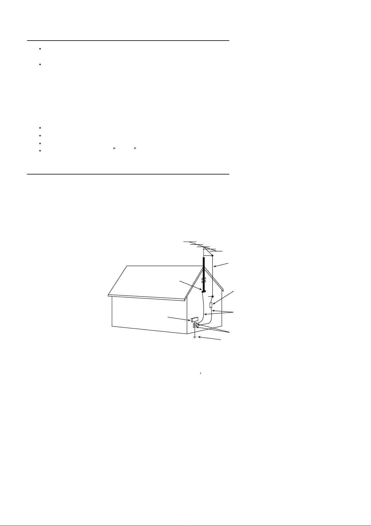
+Terr. Antenna in 75 Ohms (F type) 75 Ohms (F type) 75 Ohms (F type)
+Headphone Out --- --- ---
Connectors Front
+In Cinch (CVBS + St) --- --- ---
+In Cinch (CVBS+Mo) --- --- ---
+Headphone Out --- --- ---
Connectors Side
+In Y/C + Cinch(CVBS+St) --- --- ---
+In Y/C + Cinch Stereo --- --- ---
+In Cinch (CVBS + St) --- --- ---
+Cinch(CVBS+R/L) 111
+IN Cinch (CVBS + Mo) --- --- ---
+Headphone Out 1(ĭ3.5mm) 1(ĭ3.5mm) 1(ĭ3.5mm)
Connectors Top --- --- ---
Connectors bottom --- --- ---
+Headphone out --- --- ---
Connectors Mechanical
Styling
+Cabinet Name M61 E62 M71
+Configuration xx xx xx
+Graphics/Logo's
+Cabinet Colour Black Black Black
+Mechanics
7

+Speaker Visibility
General
+Chassis MT02(MT8202+MT8293) MT02(MT8202+MT8293) MT02(MT8202+MT8293)
+Software Delivery Mode reflashable reflashable reflashable
+Software Version
+Mains Voltage range AC 110v~240v AC 110v~240v AC 110v~240v
+Mains Frequency 50/60Hz 50/60Hz 50/60Hz
+Adaptor output power rate --- --- ---
+Type Mains Cord
+Power Supply design Internal Power Module Internal Power Module Internal Power Module
+Power Consumption (P)TV in On 220W 220W 220W
+Power Consumption SB in Watts Less than 3 Less than 3 Less than 3
+Certification CB CB CB
Final Equipment
+Packaging language English English English
+Documents and manuals Yes Yes Yes
+Cables Supplied Power Cord Power Cord Power Cord
+Antenna Supplied No No No
+Tuner detachable No No No
+Stand Supplied stand detachable stand detachable stand detachable
+wall mount bracket Supplied Optional Optional Optional
+Aux Equipm Supplied Batteries of 1.5V *2(5#) Batteries of 1.5V *2(5#) Batteries of 1.5V *2(7#)
+Dimension (Unpacked,stand included) 1058(L)x270(W)x765(H) 1062(L)x305(W)x770(H) 1058(L)x310(W)x786(H)
+Dimension (Unpacked,stand excluded) 1058(L)x115.5(W)x710.6(H) 1062(L)x118(W)x712(H) 1058(L)x116(W)x746(H)
+Dimension (Packed) 1211(L)x364(W)x889(H) 1213(L)x418(W)x877(H) 1213(L)x386(W)x906(H)
+Container Loading(20 feet Flat container) 56 40 48
+Container Loading(40 feet Flat container) 118 90 108
+Container Loading(40 feet high container) 177 90 108
+Gross Weight(Kg) 33 31 32
+Net Weight(Kg) 27.5 27.5 24
PIP/POP NO NO NO
+Type --- --- ---
+Features --- --- ---
Built-in Digital TV Reception No No No
+ATSC Tuner No No No
+DVB-S/C/T Tuner No No No
+Transmission No No No
Built-in Data System
+Text Standard --- --- ---
+(Tele)text Features
+Nbr bckgrnd page / Mem Size --- --- ---
+Text Technology
+Digital Data handling --- --- ---
+Program Guide --- --- ---
+CCD(close caption) Yes Yes Yes
+CCD- V-chip Yes Yes Yes
+Parent Lock Yes(code administrationˈChannel Lock, Video Lock) Yes(code administrationˈChannel Lock, Video Lock) Yes(code administrationˈChannel Lock, Video Lock)
8

3.1 Product Overview
Chassis MT02 is using the MT82xx series as the main chip embedded the MCU, Scaler,
RAM, Video decoder and Audio processor. The circuit outside and alignment is very simple.
The power consume is 180W˄Max.˅, the standby consume less than 1W. The Sound
speaker’s power is 2x5W.The PSU has 3 part voltage output: one 5v for standby, one 24v for
inverter, one 12v for signal process.
There are 4 boards for signal process: main board, SCART board, side AV board, keypad
board.
Support 1x RF in, 0.5x SCART, 1XSCART, 1xYPbPr, 1xVGA, 1xside AV include YC input,
1xHDMI,1x headphone out. The details please refer the SyRS.
3.2 Main Board Alignment
yBefore power on, please check and make sure the output of U27ˈU29ˈU21ˈU30ˈU20,U22,U23,U31,U37 are not shorted to grand.
ySupply 5v to JP12A and test the output of U30,U22, the normal is 3.3V+/-5%, the
U23 output should be 1.8V+/-5%.
yDownload the SW to the main chip; please see the chapter of how to download.
yCheck all the function of the all others board on the test tool.
3.3 Final Alignment
3.3.1 Port Functional pre test
Equipment Patten Standard
Tuner Cable Full band Picture & Sound is
OK
SCART
1/2/SAV-CVBS PM5418 PAL, half color &
Gray bar
Picture & Sound is
OK
SCART1/SAV-YC PM5418 PAL, half color &
Gray bar
Picture & Sound is
OK
SCART1/-RGB PM5418 PAL, half color &
Gray bar
Picture & Sound is
OK
SCART1 CVBS out Cable First channel Out put Picture &
Sound is OK
HDMI DVD with HDMI
certification Movie, 720P@60HZ Picture & Sound is
OK
VGA Chorma 2327/DVD
with VGA
1024 h768@60Hz
half color & Gray
Picture & Sound is
OK
Headphone Cable First channel Sound is OK
Loud Speaker Cable First channel Sound is OK
YUV(YPbPr) Chroma 2327/BSG-3
60A/DVD
1080i@60HZ half
color & Gray
3 ALIGNMENT PROCEDURE

3.3.2 Factory Menu
a. Enter the Field Service mode
Use the IR and press the remote key “Vol-” to “0”, press mute remote key, then press
9,7,3,5 remote key. Press right key to enter the sub-menu and press MENU key to return the
main-menu.
b. Factory Menu Definition
Factory *********** MT: V***
System Power Mode Off/Remember
Balance Factory Key On/Off
TV Geo Tuner AGC 12
Nicam Key Board Lock Off/On
Mono LOGO Off/Logo1/Logo2
Sound Pattern 0/1/2/3/4/5/6 0-Black(It’s used when Blue
Mute is off in “Other”); 1-Low
light white; 2-Red; 3-High light
white; 4-Green; 5-Blue; 6-
Continuous play 0 to 5
Other Back Light 254
Info Reset
Power mode
Remember: Keep the lately Power on state; OFF: Standby after Power on
Factory key
Shortcut key: ON The “Blue” key is the factory menu key; OFF: disabled.
Key Board Lock
ON: the keypad board is locked; only the RCU is available; OFF: disabled.
LOGO
LOGO 1; LOGO 2; OFF It’s the power ON LOGO.
Pattern
It is used design test.
Backlight
It is used for the adjustment of the LCD panel.
Reset
It is used for going back and default value.
Factory *********** MT: V***
System Source SCART/CMP/HDMI/VGA
Balance White R 128
TV Geo White G 125
Nicam White B 121
Mono Gray R 128
Sound Gray G 129
Other Gray B 128
Info RGB Calibrate
10

Source
It is the source of white balance adjusts that is SCART, CMP, HDMI, and VGA.
White R/G/B
It is used for the adjustment of white balance.
Gray R/G/B
It is used for the adjustment of gray balance.
RGB Calibrate
It is used for the software adjustment in VGA mode.
Factory *********** MT: V***
System Color system PAL
Balance H POS 63
TV Geo H Size 44
Nicam V POS 88
Mono V Size 68
Sound
Other
Info
H/V POS
It is used for the position of the horizontal and Vertical.
H/V Size
It is used for the size of the horizontal and Vertical.
Factory *********** MT: V***
System VOL_0 0
Balance VOL_10 1
TV Geo VOL_50 11
Nicam VOL_90 107
Mono VOL_100 254
Sound TV Pre 38 TV sound plus value
Other AV Pre 50 AV sound plus value
Info FW Freq 10 Default. No need Adjusting.
VOL_0/10/50/90/100
It is used for adjusting of volume curve.
TV/AV Pre
It is used for adjusting of level of volume.
11

Factory *********** MT: V***
System Blue Mute ON Switch of “BLUE” screen
Balance CTI Middle Default. No need Adjusting.
TV Geo Flash Tone ON Default. Must be “OFF” when
adjusting white balance.
Nicam Adaptive Luma Control ON Default. Must be “OFF” when
adjusting white balance.
Mono Deinterlace Mode Automatic Default. No need Adjusting.
Sound White Peak Limitator ON Default. No need Adjusting.
Other MDDi Edge Preserving High Default. No need Adjusting.
Info TTX Contrast 10 Default. No need Adjusting.
Black Level 2 Default. No need Adjusting.
Seamless OFF Default. No need Adjusting.
It is only used for design, please don’t change.
Factory *********** MT: V***
System Project LCD32MT02Y1
Balance Version ***
TV Geo Date ***
Nicam
Mono
Sound
Other
Info
It is the information of the product model, the software version and the date.
“Nicam” and “Mono” is default, don’t adjust.
Factory *********** MT: V***
System Correst Thres 5 Default. No need Adjusting.
Balance Sync Loop 50 Default. No need Adjusting.
TV Geo Error Thre 6 Default. No need Adjusting.
Nicam Parity Error Thres 47 Default. No need Adjusting.
Mono Every Num Frames 32 Default. No need Adjusting.
Sound
Other
Info
12

Factory *********** MT: V***
System High DEVI OFF
Balance AM Mute ON
TV Geo AM Mute high 69
Nicam AM Mute low 53
Mono Carrier shift OFF
Sound Saturation Mute OFF
Other FM Mute ON
Info FM Mute High 24
FM Mute Low 19
3.3.3 Factory Alignment Process
Adjust the ADC channel of signal source
1) Set “OFF” on “Flesh Tone” and “Adaptive Luma Control” in “Other” of the service menu;
Set “OFF” on “Black expand” in “PICTURE” of customer menu.
2) YUV(YPbPr), input SDTV-576i@50Hz, 100% saturation, 8-class color bar signal, then go
into “Balance ” page of service menu, set “CMP” of “Source”, choose “RGB Calibrate”,
press “Enter” key on remote control, the machine will adjust the ADC channel on CMP
situation, until show “OK”.
(Referenced instrument: Pattern37, Timing33 of 2327, or Timing79, Pattern85 of BSG360A,
or relevant output of 54200)
3) VGA, input 1024h768/60HZ, color temp signal, repeat the process before.
White Balance Adjustment (Adjusting VGA/TV/CMP, HDMI no need)
Set “OFF” on “Flesh Tone”, “Adaptive Luma Control” and “White Peak Limitator” in “Other” of
the service menu; Set “OFF” on “Black expand” in “PICTURE” of customer menu.
i. White balance and color temperature adjusting on VGA state.
1) On VGA state, go into “balance” of service menu.
2) Input 640h480 8-class gray signal, test color coordinate with a color analyzer.
A. On the 3rd gray of the bright side. Then adjust White R and White G and White B until the
data on the analyzer become x=282f10, y=293f10, also bright value ˚220 nit.
B. On the 3rd gray of the dark side. Then adjust Gray R and Gray G and Gray B until the data
on the analyzer become x=282f10, y=293f10, also bright value ˘25 nit.
ii. White balance and color temperature adjusting on TV/AV state.
1) On AV state, go into “balance” of service menu.
2) Input 8-class gray signal, test color coordinate with a color analyzer
A. On the 3rd gray of the bright side. Then adjust White R and White G and White B until the
data on the analyzer become x=282f10, y=293f10, also bright value ˚220 nit.
B. On the 3rd gray of the dark side. Then adjust Gray R and Gray G and Gray B until the data
on the analyzer become x=282f10, y=293f10, also bright value ˘25 nit.
C. Iterative adjusting between bright and dark side, until A&B all meet request.
13

iii. White balance and color temperature adjusting on CMP state.
1) On CMP state, go into “balance” of service menu.
2) Input 576i/50Hz 8-class gray signal, test color coordinate with a color analyzer
A. On the 3rd gray of the bright side. Then adjust White R and White G and White B until the
data on the analyzer become x=282f10, y=293f10, also bright value ˚220 nit.
B. On the 3rd gray of the dark side. Then adjust Gray R and Gray G and Gray B until the data
on the analyzer become x=282f10, y=293f10, also bright value ˘25 nit.
C. Iterative adjusting between bright and dark side, until A&B all meet request.
Remarks: after ADC adjusting and white balance adjusting, “Flesh Tone” and “Adaptive Luma
Control” of “Other” in service menu should be set “ON”; “Black expand” of “Picture” in customer
menu should be set “ON”.
3.4 Update the software
The software can be updated on board and also can be update through the VGA port, do not need
to open the cabinet.
Please install the MT8202 driver and parallel driver first. Need to prepare a special cable.
IFirst time download on board
1) Connect by cable (the tool and the cable) between the PC and the XPA5 on the board.
2) Supply 5V to the main board by JP12A or POWER on.
3) Open the MT8202 driver as below:
4) Then select “Browse” open the attached file (MT02.bin) in the location. In order to
ensure it can be better updated, you can set the “baud rate” be “115200”.
5) Select “update”, when the rate of the progress get to 100%, the update finished.
14

6) After update finished, power off the TV, then power on, at the first time that you power
on the TV set, the display will be later than normal.
II Update through the VGA port.
1) Connect by the cable (the tool and the cable) between the PC and the VGA port.
2) Power on the set, press the key of the factory remote control. After repeat that process
3,4,5,6 above, please note when doing the process 6, must erase flash first: press
“ERASE FLASH”.
3.5 The DDC data should be programmed before SMT, and it also can be updated through
P2 (VGA) when finished SMT.
3.6 After download the software, it need about 30 second to initialize the EEprom, so must
write the data to U2 before SMT.
3.7 IC need to be update
Location Materiel NO. Virtual coding
U2 13-M24C32-MNB E2PROM
15

1ǃOVERALL DESCRIPTION:
Chassis MT02 is using the MT82xx series as the main chip embedded the MCU, scaler,
video decoder and audio processor. The circuit outside and alignment is very simple. The decoder
IC MT8202 is made by MTK which is the company in Taiwan.MT8202 is a highly integrated
single chip for LCD TV, it includes 3D comb fliter TV decoder to retrieve the best image from the
popular composite signals.
1.1 VIDEO INPUT:
1 Support fully programmable 8 composite/s video input pins
2 Support 2 component input with SDTV format & HDTV 480p/720p/1080i format
3 Support 1 VGA input up to SXGA(1280*1024*75hz) including SOG singals
4 Support DVI 24 bit RGB signal input
1.2 TV DECODER:
Support PALǃNTSCǃSECAM
2ǃINPUT AND OUTPUT
There are 5 boards for signal process: main boardǃhigh frequency boardǃSCART boardǃside AV board and keypad board
2.1 INPUT PORT˖Video:
AV1(scart1), AV2(scart2),AV3(side AV ),YPbPr,VGA,HDMI
Audio:
AV1L/R,AV2 L/R, AV3 L/R,YPbPr and VGA use the same L/R port,HDMI.
2.2 OUTPUT PORT˖Video :
AV1 and AV3 (SCART2), TV (SCART1)
Audio:
AV1 L/R and AV3 L/R(SCART2),TV(SCART1).HEADPHONE L/R
3ǃMT02 SIGNAL FLOW CHART
4 MT02 CIRCUIT DESCRIPTION
16

According to the main board edition E
4ǃKEY COMPONENTS LIST˖Serial no. Part no. Name of IC function
U3 13-MT8202-AGB LCDMT8202AG CPU\video
decoder\scaler\nicam
decoder
U4/U5 13-281622-ETB5 HY5DU281622ET-5 DDR SDRAM
U7 13-AL016M-90B 16M
S29AL016M90TFI02
FLASH
U2 13-M24C32-MNB M24C32-WMN6(S08) System EEPROM
17

U27 13-SC2602-S0B SC2602 DC-DC
U29 13-D13N03-LIB OHKD13N03LT Dual mos
U6 13-SO2996-
BEBNL
SP2996BEN-L/TR DDR termination
U36 13-CM2021-00B CM2021-00TR HDMI ESD
U8 13-MT8293-E0B HDMI PANELLINK
CINEMA RECEIVER
MT8293E
HDMI Decoder
U10 13-AT24C0-2BB 2K AT24C02BN-10SU-
1.8
HDMI DDC
EEPROM
U9 13-00M24C-08B 8K M24C08 HDMI HDCP
EEPROM
U11 13-AT24C0-2BB 2K AT24C02BN-10SU-
1.8
VGA DDC EEPROM
U2(SCART BOARD) 13-HC4052-
PWBPH
74HC4052PW AV1\AV2\AV3 Audio
Switch
U13 13-HC4052-
PWBPH
74HC4052PW Audio switch
U12 13-CS5340-00B CS5340 Audio ADC
U15 13-CS4334-KSB CS4334KSSO-
8STEREOD/A
Audio DAC
U17 13-RC4558-DRB RC4558DR Audio amplifier
U18 13-RC4558-DRB RC4558DR Audio amplifier
U16 13-YDA138-E0B YAD138-E Digital Audio power
amplifier
U14 13-PI5V33-0QB PI5V330Q Vedio switch
5ǃBRIEF DESCRIPTIONS OF SOME ICs
5.1 U3
MT8202 is a highly integrated single chip for LCD TV supporting video input and output
format up to HDTV. It includes 3D comb filter TV decoder to retrieve the best image from popular
composite signals. Embedded HDTV/VGA decoders let the high bandwidth input signals perfectly
reproduced.24/16/8 bits digital port may accept all kinds of extemal digital input video
source..New 2nd generation advanced motion adaptive de-interlacer converts accordingly the
interlace video into progressive one with overlay of a 2D Graphic processor. Advanced full
function color processing with fully 10-bit path provides high quality video contents. Independent
two Flexible scalers provide wide adoption to various LCD panels for two of different video
sources at the same time. Its on-chip audio processor decodes analog signals from tuner with lip
sync control. delivering high quality post-processed sound effect to customers. On-chip
microprocessor reduces the system BOM and shortens the schedule of UI desigh by high level C
program.MT8202 is a cost-effective and high performance HDTV ready solution to LCD TV
manufactures.
Block Diagram
18

5.2 U4/U5
The Hynix HY5DU281622ET air a 134,217,728-bit CMOS Double Data Rate(DDR)
Synchronous DRAM,ideally suited for the main memory applications which requires large
memory density and high bandwidth.
The Hynix 128Mb DDR SDRAMs offer fully synchronous operations referenced to both
rising and falling edges of the clock.While all addresses and control inputs are latched on the
rising edges of the CK(falling edges of the /CK),Data,Data strobes and Write date masks inputs
are sampled on both rising and falling edges of it.The data paths are intermally pipelined and 2-bit
prefetched to achieve very high bandwidth.All input and output voltage levels are compatible with
SSTL_2.
Block Diagram 8M*16
1

5.3 U7
The S29AL016M is a 16Mbit,3.0 volt-only flash memory organized as 2,097,152 bytes or
1,048,576 words.
20
Table of contents
Other TCL TV manuals