TDK CH101 User manual

AN-000349
Chirp Microsystems reserves the right to change
specifications and information herein without notice.
Chirp Microsystems
2560 Ninth Street, Ste 200, Berkeley, CA 94710 U.S.A
+1(510) 640–8155
www.chirpmicro.com
Document Number: AN-000349
Revision: 1.0
Release Date: 02/16/2022
Application User Guide for Floor Type Detection
and Cliff Detection for Robotic Vacuums

AN-000349
Document Number: AN-000349 Page 2 of 23
Revision: 1.0
Table of Contents
1INTRODUCTION .........................................................................................................................................................................3
1.1 SCOPE...........................................................................................................................................................................................3
1.2 THEORY OF OPERATION....................................................................................................................................................................3
1.3 REFERENCE DOCUMENTATION...........................................................................................................................................................4
2REQUIREMENTS AND SETUP ......................................................................................................................................................5
2.1 LIST OF REQUIRED HARDWARE ..........................................................................................................................................................5
2.2 ACOUSTIC INTERFACE.......................................................................................................................................................................5
2.3 MECHANICAL AND MODULE SETUP ....................................................................................................................................................6
2.4 SMARTSONIC AND DAUGHTERBOARD..................................................................................................................................................7
2.4.1 Smartsonic Connections to Run the Cliff and Floor Detect Demo Software ..............................................................................7
2.5 SOFTWARE SETUP............................................................................................................................................................................9
2.5.1 Flashing Firmware.....................................................................................................................................................................9
3GUI OVERVIEW ........................................................................................................................................................................10
3.1 GUI HEADERS ..............................................................................................................................................................................10
SETTINGS.........................................................................................................................................................................................11
3.2 ........................................................................................................................................................................................................11
3.3 UNDERSTANDING THE GUI OUTPUTS................................................................................................................................................13
4TROUBLESHOOTING AND FAQ .................................................................................................................................................14
5APPENDIX ................................................................................................................................................................................15
6REVISION HISTORY...................................................................................................................................................................23

AN-000349
Document Number: AN-000349 Page 3 of 23
Revision: 1.0
1INTRODUCTION
This guide will explain the software and hardware setup of the floor type detection and cliff detection for robotic vacuum applications
using two CH101 or ICU-10201 sensors. Floor type detection is the differentiation between hard floors (hardwood, tile, etc) and soft
floors (carpets). Cliff detection is the detection of a cliff, such as an overhanging ledge, stairs, or other similar risk to a Robotic Vacuum
Cleaner (RVC).
For clarity and simplicity, unless otherwise specified, any information referring to the CH101 in this document will also apply to the
ICU-10201.
1.1 SCOPE
This document will help users set up and run the Cliff and Floor Type Detection Demo and be able to see the correct output and
behavior from the CH101 sensors. This document solely covers the application of using two CH101 sensors to detect both cliff and
floor types. For applications where only floor type detection is needed, refer to AN-000240.
For the cliff and floor type detection algorithms to work properly, the sensors require a specific Acoustic Interface design. The Acoustic
Interface tunes the sensor’s behavior for optimal performance for this application. Users should first implement the reference Acoustic
Interface design highlighted in this document as it is optimized for the default settings in the software algorithms. Custom acoustic
designs will require experimentation from the user and are outside the scope of this document.
1.2 THEORY OF OPERATION
The CH101 is an ultrasonic Time-of-Flight (ToF) transceiver that measures the distance of an object based on how long it takes for
ultrasound transmitted from the sensor to be reflected back and received by the sensor. There is a certain amount of time after
transmission for the sensor to stop vibrating (ringdown) from the transmit pulse before it can accurately receive the reflected ToF
signal. To get around the ringdown issue while operating only a few centimeters from the floor, a second sensor is used as a dedicated
receiver and the two sensors operate in Pitch-Catch mode. In this mode, the receiving sensor does not have to deal with the ringdown
issue and it’s time constraints.
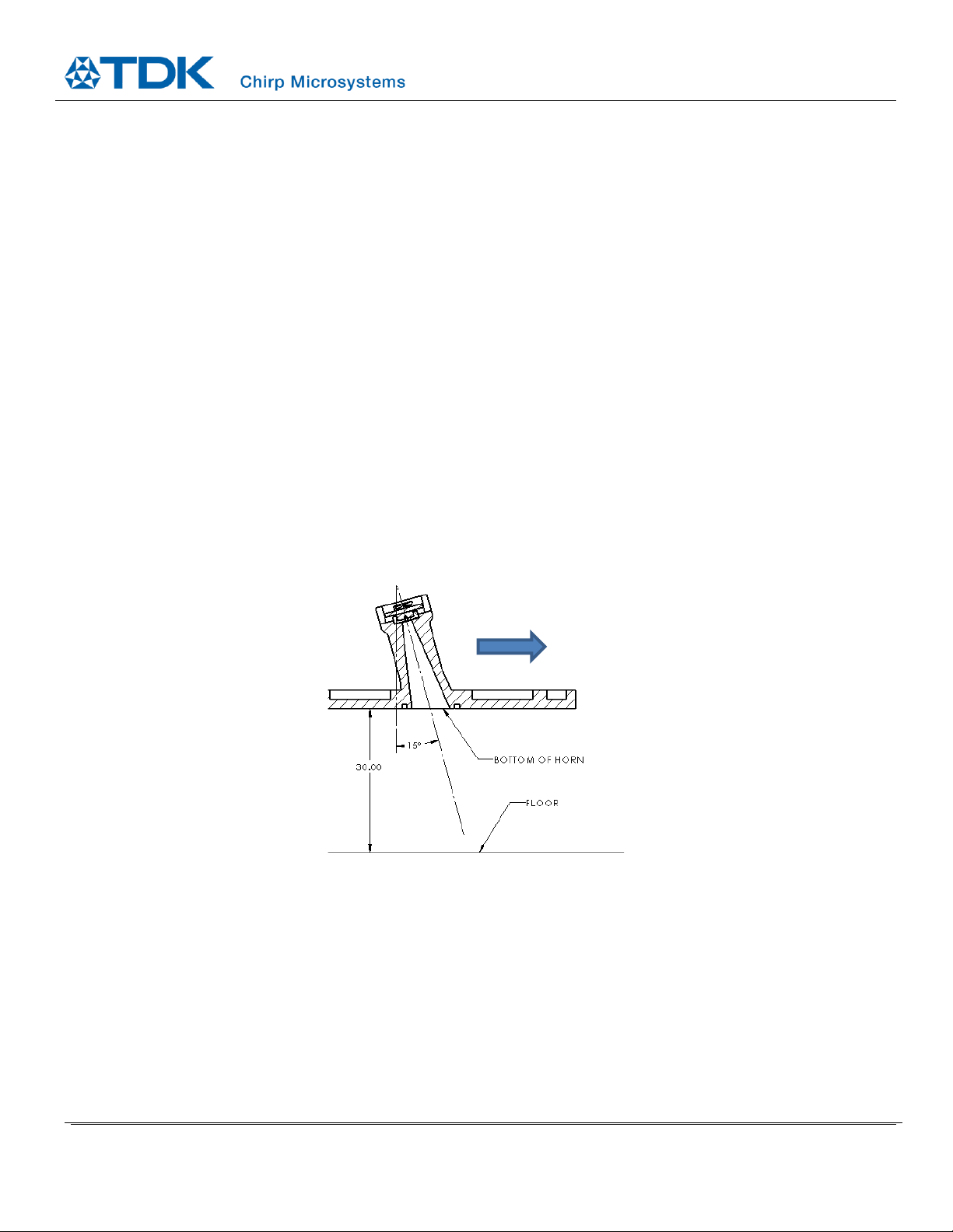
Figure 1. Diagram showing operating principle of the two-sensors in Pitch-Catch for this cliff and floor type detection application.
Different surfaces (floor types) will produce different amplitude reflections, with soft floors reflecting less and producing a lower
amplitude echo, while hard surfaces will produce a higher amplitude echo. The ToF of this echo also indicates how far away the sensor
is from the floor. When the ultrasound echo’s ToF is longer than a specified time duration, it means that there is a large gap between
the sensor and the floor, thus indicating there is a cliff in front of the sensor.

AN-000349
Document Number: AN-000349 Page 4 of 23
Revision: 1.0
1.3 REFERENCE DOCUMENTATION
In addition to information provided in this document, below are reference documentation that will be useful in understanding and
integrating the CH101 and cliff and floor type detection in your device.
•Overview of the CH101 ultrasonic ToF sensor product
oLink: invensense.tdk.com/products/ch101/
oIncludes Application Note documentation and product specific designs
•CH101 and CH201 SmartSonic Evaluation Kit Users Guide: AN-000180
oBasic concepts of ultrasonic sensing
•CH101 Mechanical Integration Guide: AN-000158
oMechanical design (including geometry, part and assembly tolerance, material, and PIF)

AN-000349
Document Number: AN-000349 Page 5 of 23
Revision: 1.0
2REQUIREMENTS AND SETUP
2.1 LIST OF REQUIRED HARDWARE
•DK-CHx01 evaluation kit (SmartSonic board)
•Micro-USB cable
•(2) CH101-02ABR sensor modules (optimized for pitch-catch applications)
•(2) 8-position FFC cables to connect the sensors to the SmartSonic board
•Dual sensor horn Acoustic Interface designed for this cliff and floor type detect application (see Section 2.2 for details)
•Miscellaneous hardware to mount and secure the dual sensor horn
2.2 ACOUSTIC INTERFACE
The two-sensor cliff detection reference design utilizes a carefully designed Acoustic Interface to achieve optimal performance.
Dimensions, tolerances, and assembly requirements for the Acoustic Interface are provided in more detail in the Appendix. Dimensions
of alignment and mounting features that are not specified in the drawing are not critical to performance and such features can be
modified as needed. A picture of the reference design Acoustic Interface is shown below.
Figure 2. (a) Side view, (b) top isometric view and (c) bottom isometric view of the 2-sensor cliff detect Acoustic Interface reference design.
Figure 3. Cross section view of the 2-sensor cliff detect Acoustic Interface reference design, highlighting the components in the module.

AN-000349
Document Number: AN-000349 Page 6 of 23
Revision: 1.0
To simplify the evaluation and prototyping phase, certain aspects of the design can be simplified without significantly altering sensor
behavior and performance:
•PIF can be omitted
•Dimensions may be relaxed beyond tolerances stated in the drawing, though performance degrades more the further this is
relaxed.
If testing with 3D printed parts:
•Use a high quality SLA 3D printer (0.05mm layer thickness or smaller)
•It is strongly recommended to inspect parts for dimensional accuracy
•Multiple 3D printing iterations may be required to fine tune dimensions and tolerances depending on your 3D printer and/or
material
2.3 MECHANICAL AND MODULE SETUP
The floor type and cliff detection algorithm are tuned and expect the sensor to be placed and orientated in a specific position for
optimal performance. The recommended design places the bottom on the Acoustic Interface 30mm from the floor. The bottom surface
of the RVC containing the Acoustic Interface should be parallel to the floor and the angle of the axis of the horn should be tilted 15
degrees from vertical. The forward tilt of the horn allows the sensor to “look” ahead and detect cliffs earlier. However, too much tilt
will result in less of the reflected signal from the floor being returned to the sensor, reducing algorithm accuracy.
Figure 4. Cross section of one of the sensor modules, showing the recommended default mounting configuration. The bottom of the horn should
be positioned 30mm above the floor, with the horn tilted and pointing forwards at a 15 degree angle.
Robot
forward
motion

AN-000349
Document Number: AN-000349 Page 7 of 23
Revision: 1.0
2.4 SMARTSONIC AND DAUGHTERBOARD
Figure 5. SmartSonic inputs, outputs, and header pins. Note: Horn design may differ from picture (green piece in picture).
2.4.1 SmartSonic Connections to Run the Cliff and Floor Detect Demo Software
1. Connect one end of the 8POS FFC cable to the Sensor-0 connector and the other into the CH101 sensor module. Repeat this
for the Sensor-1 connector and the second CH101 sensor module. The blue LED next to each connector will light up if
connected correctly (see Figure 6). If an LED does not light up, check the cable connection and/or flip the cable orientation
and try again.
2. If not already done, for power selection, move the jumper to short the FTDI pins (as shown in picture).
3. Connect all (4) J3 jumpers (as shown in picture).
4. Toggle the switch from U15 to J6 to use Sensor-0, and NOT the on-board sensor.
5. Connect the micro-USB cable to the UART/USB micro-USB connector.

AN-000349
Document Number: AN-000349 Page 8 of 23
Revision: 1.0
Figure 6. Example of SmartSonic module connection. Note: cable orientation may differ depending on your particular cable’s construction.

AN-000349
Document Number: AN-000349 Page 9 of 23
Revision: 1.0
2.5 SOFTWARE SETUP
1. Install the cliff detect demo with the installer executable. The default installation folder is “C:\TDK-InvenSense\Chirp Cliff and
Floor-type Detection Demo-X.X.X”.
2. Once the demo installation is complete, double click “cliff_floor_demo.exe”to launch the demo GUI.
3. If needed, flash the SmartSonic with the required firmware (see 2.5.1 Flashing Firmware).
4. In the GUI, select the correct COM port device (click refresh if needed), then click “Connect”. The demo is now running.
Various plots and fields in the GUI will being displaying and streaming data from the sensors.
2.5.1 Flashing Firmware
The SmartSonic board should already be pre-flashed with the correct firmware to run the cliff detection demo. In the event you need
to reflash the firmware or flash a different firmware, the steps to do this are:
1. Power off the board by unplugging the micro-USB cable.
2. Move the power selection jumper to bridge the EDBG pins (middle position, as shown in Figure 7).
3. Plug the micro-USB cable into the EDBG-USB connector.
4. In the demo GUI, in the upper left corner on the GUI, click on the down arrow next to “Connect” to show the firmware flash
dropdown menu.
5. Click “Flash Default Firmware” to flash the default firmware, or click “Flash Firmware” to select a specific firmware file to flash.
6. Wait for the firmware flash to complete. The amber LED on the SmartSonic will blink repeatedly during this process. The GUI
will show a prompt once flashing is complete.
7. Unplug the micro-USB cable from the board.
8. Move the power jumper back to the first position to bridge the FTDI pins (as shown in Figure 5).
9. Plug the micro-USB cable back to the UART/USB connector.
Figure 7. Power jumper position for firmware flashing.

AN-000349
Document Number: AN-000349 Page 10 of 23
Revision: 1.0
3GUI OVERVIEW
Figure 8. Example GUI display output.
3.1 GUI FIELDS
•Device: This field selects the COM port for the board and connects/disconnects the board with
“Connect/Disconnect”button. Device algorithm settings can also be modified by clicking the button.
See Section 3.2 for a detailed explanation of device settings.
•Record: Input and output data can be saved in 3 separate files using the “Record” checkbox.
oThe algorithm input data will be saved in the specified directory in a timestamped text file. A json
file with the same root name is created and contains information about the sensor configuration.
oThe algorithm output data will be saved in the subfolder “algo/cliff_detection_emd” in csv format.
oFor cliff detect data, the data format is:
timestamp | algorithm type | tx sensor id | rx sensor id | detection result | cliff_index | cliff depth
estimate
oFor floor type data, the data format is:
timestamp | algorithm type | tx sensor id | rx sensor id | floor type metric | decision threshold | floor
type result | start mag derivative(for debug)
•Widgets: Click the “ASCAN” button to open the A-scan (amplitude scan) widget. Highest amplitudes are
bright yellow, while lowest amplitudes are dark violet. This color scale is relative to the amplitude ranges
being currently shown on the A-scan, and does not represent the absolute amplitude values.
•Cliff Detection: Output from the cliff detect algorithm on the current cliff status (“Cliff” or “Floor”)

AN-000349
Document Number: AN-000349 Page 11 of 23
Revision: 1.0
•Floor Type: Output from the floor type algorithm on the current floor type status (“Hard Floor” or “Soft
Floor”)
•Floor/Cliff Data: Numerical output values from both algorithms
•Magnitude: Displays the magnitude of the current echo measured by the sensor. The x-axis shows the
range samples (which translates to time/distance) provided by the sensor. The y-axis is the amplitude of
the received signal.
•Cliff Depth Estimate:Shows the cliff depth estimate over time. To obtain the cliff depth, the sensor
height needs to be subtracted when the sensor is above the floor.
•Floor Type Metric: The floor type metric plot shows the floor type metric over time with respect to the
adaptive threshold. If the metric is below the threshold, the floor type is considered as a soft floor. If the
metric is above the threshold, the floor type is considered as a hard floor.
3.2 SETTINGS
If settings are to be changed, this needs to be done before the board is connected with the “Connect” button.
Figure 9. Default sensor settings.

AN-000349
Document Number: AN-000349 Page 12 of 23
Revision: 1.0
Sensor settings:
•ODR: The time interval at which the sensor should be periodically triggered to take a measurement. Reducing ODR increases
the data bandwidth required to transfer data from the sensor to the host. A 40ms ODR is equal to a data acquisition frequency
of 25Hz. Default value is 40ms. Range of permitted values is [10, 1000].
•Max range in samples: The number of IQ traces to acquire for each sensor measurement. Higher values allow the sensor to
search for echoes further away, but also increases the amount of data collected, the data transfer time, and data processing
time. The cliff detection algorithm has the best performance at 40 samples. Default value is 40 samples. Range of permitted
values is [20, 80].
Mechanical Device settings:
Note: Changing mechanical device settings from default values may require re-tuning cliff and/or floor type parameter settings to
achieve optimal algorithm performance.
•Sensor height: Distance between the floor and the bottom of the horn (e.g. bottom of the robot) in mm. Default value is
30mm. Range of permitted values is [0, 140].
•Horn/Tube length: Length of horn/tube in mm. Default value is 18mm. Range of permitted values is [2, 50].
•Distance between 2 sensors: Center-to-center distance between the two sensors (how far they are spaced apart from each
other). Default value is 11mm. Range of permitted values is [10, 60].
•Sensor tilt angle: Sensor tilt angle relative to the floor, in degrees. Sensor pointing directly down at the floor is 0 degrees.
Default value is 15 degrees. Range of permitted values is [0, 45].
•For best algorithm performance, all physical input measurements should be accurate to +/- 1 mm or +/- 1 degree.
Cliff Parameters settings:
•Min cliff depth to detect: The minimum cliff depth that should be detected and considered as a cliff. Cliff depths that are
smaller than this value will be treated as a regular floor. Default value is 30mm. Range of permitted values is [10, 140].
•Amplitude value to detect near cliff: The amplitude threshold to consider an ultrasound echo as a short-range cliff. Default
value is 4000 LSBs.
•Amplitude value to detect far cliff: The amplitude threshold to consider an ultrasound echo as a long-range cliff. Default
value is 2000 LSBs.
•Voting window length: Length of detection voting window in number of frames. This parameter is used to smooth the
instantaneous detection result. Lower values will result in faster algorithm reaction, but also will increase likelihood of false
cliff detections. Set this parameter to balance between reaction time and false detection frequency. Default value is 11
frames. Range of permitted values is [1, 101].
Floor Type Parameters settings:
•Threshold soft floor: Initial threshold on the floor type detection metric. Values below this threshold will be considered a soft
floor.
•Threshold hard floor: Initial threshold on the floor type detection metric. Values above this threshold will be considered a
hard floor.
Buttons:
•Import: Import parameters from json file. The json file format must be the same as the “Export” button.
•Export: Export parameters to json file.
•OK: Apply modifications and close window.
•Cancel: Discard modifications and close window.

AN-000349
Document Number: AN-000349 Page 13 of 23
Revision: 1.0
3.3 UNDERSTANDING THE GUI OUTPUTS
The “Magnitude” plot displays the return echo signal as measured by the receive-only sensor. The first peak is the initialize phase of
the receive sensor, which results from powering up and waking the sensor. The second peak is the actual echo from the floor, that
was originally sent from the transmitter sensor. The relative magnitude of this peak determines whether the algorithm will classify the
floor as a soft floor (low amplitude) or hard floor (high amplitude).
The “Floor Type Metric” plot displays the algorithm’s calculated metric for the amplitude of the floor’s return echo over time. If the
RVC is transitioning between hard and soft floors, the metric’s displayed value will correspondingly change along such floor transitions.
While the RVC is moving, there will be some fluctuations in the floor type metric, and is normal sensor behavior.
The “Cliff Depth Estimate” plots the cliff detect algorithm’s estimate for the cliff depth/size over time. In the Magnitude plot, the floor
echo’s position will determine if the algorithm classifies the situation as a floor or cliff. If the echo is too far away, or no echo is detected,
the algorithm will consider it a cliff situation. If the sensor or RVC is moved up and down relative to the floor, this plot will
correspondingly track the sensor/RVC’s vertical motion.

AN-000349
Document Number: AN-000349 Page 14 of 23
Revision: 1.0
4TROUBLESHOOTING AND FAQ
•The GUI does not display any signal: Verify all connections. Reset the board by pressing reset button on the board. If it is still
not working, flash the board with the Default firmware using the arrow down button next to the Connect/Disconnect button.
Also, verify that the correct firmware is flashed.
•Firmware flash produces an error:
Check that the USB cable is plugged into the EDBG port for flashing. Check that the jumper is in the correct position.
•I reduced the ODR and now the GUI does not display any signal: Possibly the FTDI driver latency on your computer is set too
high. To fix this issue, 1) go to device manager / Ports (COM & LPT), 2) select your FTDI COM port, 3) right-click on port
properties / Port Settings / advanced 4) in BM Options, set latency timer to 1 ms. 5) reset the board, restart the GUI. You
should now be able to see the signal with ODR set to 10ms.
•Cliff or floor performance is not good: Verify the physical dimensions of the mechanical device settings. The parameters need
to be accurate by +/- 1mm or +/- 1 degree for best performance.
•High cliff is not detected: Decrease parameter “Amplitude value to detect far cliff” (steps of 500 recommended)
•Small cliff is not detected: Decrease parameter “Min cliff depth to detect” (steps of 1 mm) or decrease parameter “Amplitude
value to detect near cliff (steps of 500 recommended)
•Floor is detected as cliff: Increase parameter “Amplitude value to detect near cliff” (steps of 500) or increase parameter “Min
cliff depth to detect (steps of 1 mm)
•Hard floor is classified as soft floor: Increase “Threshold hard floor” and/or decrease “Threshold soft floor”. Recommended
value: “Threshold hard floor” <= 2x min amplitude of hard floor metric within temporal window of 8 samples.
•Soft floor is classified as hard floor: Increase “Threshold soft floor” and/or decrease “Threshold hard floor”. Recommended
value: “Threshold soft floor” >= 2x max amplitude of soft floor metric within a temporal window of 8 samples.

AN-000349
Document Number: AN-000349 Page 15 of 23
Revision: 1.0
5APPENDIX
5.1

AN-000349
Document Number: AN-000349 Page 16 of 23
Revision: 1.0

AN-000349
Document Number: AN-000349 Page 17 of 23
Revision: 1.0
•

AN-000349
Document Number: AN-000349 Page 18 of 23
Revision: 1.0

AN-000349
Document Number: AN-000349 Page 19 of 23
Revision: 1.0
•

AN-000349
Document Number: AN-000349 Page 20 of 23
Revision: 1.0
o
Other manuals for CH101
1
This manual suits for next models
1
Table of contents
Other TDK Accessories manuals