TDK PowerHap Installation and operating instructions

Piezo Haptic Actuators - PowerHap
Application note for evaluation kit 60 V
Series/Type:
Ordering code: Z63000Z2910Z1Z44
Date: 2019-05-08
Version: 1.6
TDK Electronics AG 2019. Reproduction, publication and dissemination of this publication, enclosures hereto and the
information contained therein without TDK Electronics' prior express consent is prohibited.
Content of header bars 1 and 2 of data sheet will be automatically entered in headers and footers! Please fill in the table and then
change the color to "white". This ensures that the table disappears (invisible) for the customer PDF.
Don't change formatting when entering or pasting text in the table and don't add any cell or line in and to it!
Identification/Classification 1
(header 1 + top left bar):
Piezo Haptic Actuators - PowerHap
Identification/Classification 2
(header 2 + bottom left header bar):
Application note for evaluation kit 60 V
Ordering code: (top right header bar) Z63000Z2910Z1Z44
Series/Type: (bottom right header bar)
Preliminary data (optional): Preliminary data
Department: PPD PI AE/IE PD
Date: 2019-05-08
Version: 1.6
Prepared by: Roman Puchleitner
Signed by: Harald Kastl, Andreas Pentscher-Stani, Roman Puchleitner

Piezo Haptic Actuators - PowerHap Z63000Z2910Z1Z44
Application note for evaluation kit 60 V
Preliminary data
PPD PI AE/IE PD 2019-05-08
Please read Cautions and warnings and Page 2 of 28
Important notes at the end of this document.
1Introduction ...................................................................................................................................................... 4
1.1Ordering code .......................................................................................................................................... 4
1.2Features ................................................................................................................................................... 5
1.3Description ............................................................................................................................................... 5
2Quick start guide .............................................................................................................................................. 6
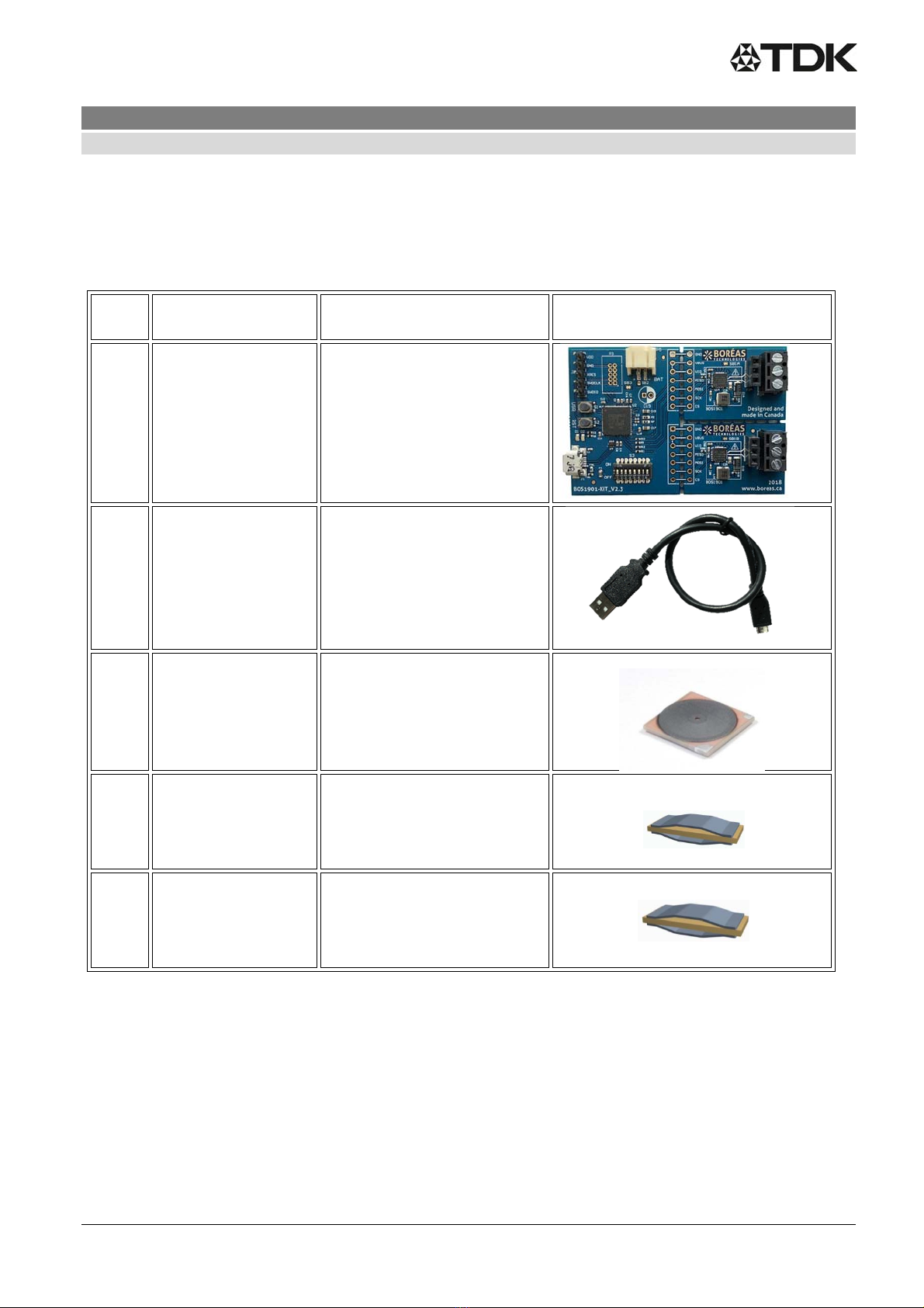
2.1What is in the box .................................................................................................................................... 6
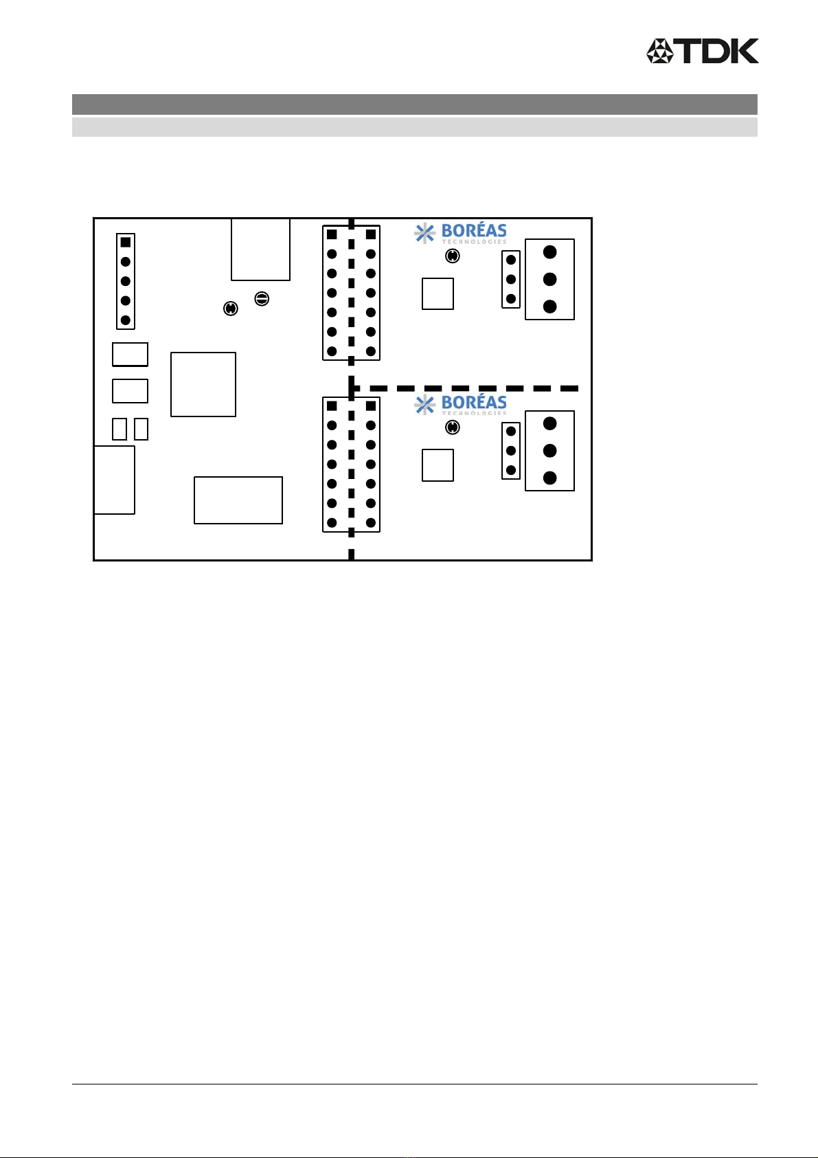
2.2PCB overview .......................................................................................................................................... 7
2.3Quick start procedure .............................................................................................................................. 7
3Hardware ......................................................................................................................................................... 8
3.1Jumper options ........................................................................................................................................ 8
3.1.1Use BAT power (external power supply connection) .......................................................................... 8
3.1.2Use UPI feature ................................................................................................................................... 9
3.2Piezo actuators ........................................................................................................................................ 9
3.3DIP switch settings ................................................................................................................................ 10
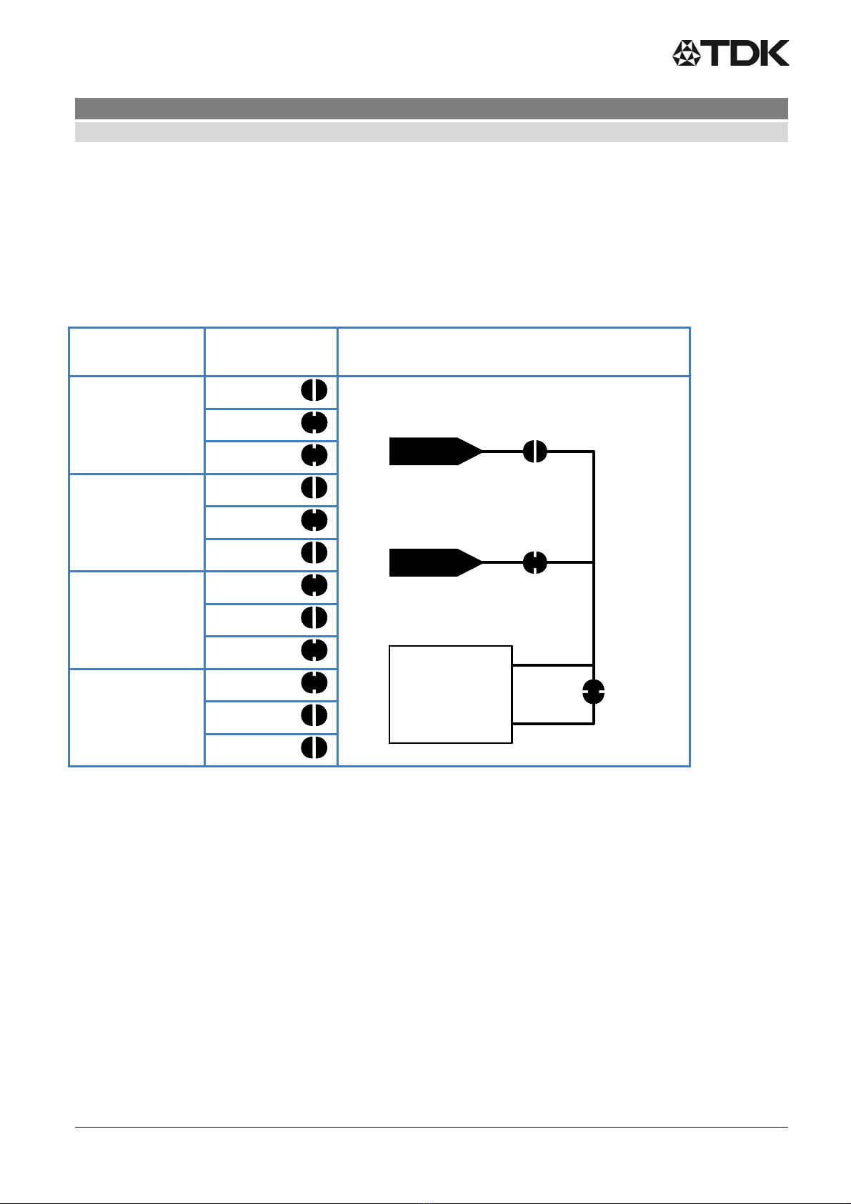
3.4Output configuration options .................................................................................................................. 12
3.4.1Differential output configuration ......................................................................................................... 12
3.4.2Single ended output configuration ..................................................................................................... 12
3.5Breakable units ...................................................................................................................................... 13
4Software ......................................................................................................................................................... 13
4.1Software installation procedure ............................................................................................................. 13
4.2Software operation ................................................................................................................................. 13
5Firmware ........................................................................................................................................................ 14
5.1Identifying the firmware revision number ............................................................................................... 14
5.2Firmware installation / update procedure .............................................................................................. 15
5.3Firmware modification – using PSoC® CreatorTM ................................................................................. 16
5.4Adjusting sensing feedback parameters ................................................................................................ 17
5.4.1Sensing feedback amplitude .............................................................................................................. 17
5.4.2Sensing feedback frequency ............................................................................................................. 17
5.4.3Sensing threshold .............................................................................................................................. 17
5.4.4Response type ................................................................................................................................... 18
6Design reference ........................................................................................................................................... 19
6.1Schematics ............................................................................................................................................ 19
6.2PCB Layout ............................................................................................................................................ 21
6.3Bill of materials ...................................................................................................................................... 23
7FAQ and troubleshooting ............................................................................................................................... 24
8Notes and warnings ....................................................................................................................................... 24

Piezo Haptic Actuators - PowerHap Z63000Z2910Z1Z44
Application note for evaluation kit 60 V
Preliminary data
PPD PI AE/IE PD 2019-05-08
Please read Cautions and warnings and Page 3 of 28
Important notes at the end of this document.
9Document history ........................................................................................................................................... 25
Cautions and warnings .......................................................................................................................................... 26
Remark .................................................................................................................................................................. 26
Display of ordering codes for TDK Electronics products ....................................................................................... 26

Piezo Haptic Actuators - PowerHap Z63000Z2910Z1Z44
Application note for evaluation kit 60 V
Preliminary data
PPD PI AE/IE PD 2019-05-08
Please read Cautions and warnings and Page 4 of 28
Important notes at the end of this document.
1 Introduction
This evaluation kit was developed to support engineers during their first steps designing applications with the
PowerHapTM piezo actuators for haptic feedback.
The design is not qualified regarding manufacturing and operation over the whole operation temperature range
or lifetime.
This evaluation kit provided by TDK is intended to be used for functional testing only.
Due to their purpose, evaluation driver kits are not intended to be used by the same procedures regarding
returned material analysis (RMA) and process change notification (PCN) as regular products.
The board described is an evaluation driver board dedicated for laboratory environment
only. It operates at voltages up to 100V. This board must be operated by qualified and
skilled personnel familiar with all applicable safety standards.
1.1 Ordering code
The ordering code for this evaluation kit is Z63000Z2910Z 1Z 44.
.

Piezo Haptic Actuators - PowerHap Z63000Z2910Z1Z44
Application note for evaluation kit 60 V
Preliminary data
PPD PI AE/IE PD 2019-05-08
Please read Cautions and warnings and Page 5 of 28
Important notes at the end of this document.
1.2 Features
Plug and play developer kit to experience piezo haptic feedback/sensation
Including the BOS1901-KIT for the low-power BOS1901 integrated circuit by Boreas Technologies,
a high voltage driver with digital interface
o Simple power interface for development via USB port
o Standard USB audio to prototype haptic effects in MATLAB®, Python®, Audacity® and
many other software1
o Fully embeddable modular software driver
o Easy generation of high-voltage waveforms up to 70 Vpp for the PowerHap
o Two breakable miniature PCBs with BOS1901 drivers
TDK PowerHap actuators included in the kit (1 pcs each, with wire):
o 0909H011V060 (previously known as 2.5 G)
o 0904H014V060 (previously known as Lateral Mini 9 x 3.75)
o 1204H018V060 (previously known as Lateral Mini 12 x 4)
1.3 Description
The BOS1901-KIT is a development kit to support users who want to get familiarized with the BOS1901 piezo
haptic driver IC.
The USB powered kit appears as an USB audio device for the computer, which allows the rapid generation of
waveforms using existing audio software like Audacity® for haptic prototyping. Each breakable miniature PCB
gives access to all signals allowing the user to experiment with the BOS1901 using a development platform of
his/her choice.
Figure 1: Simplified BOS1901 - KIT diagram.
------------------------------------------------------------
1 MATLAB® is registered trademark of The MathWorks, Inc.
Python® is a registered trademark of the PSF
Audacity® is a registered trademark of Dominic Mazzoni
BOS1901
breakable PCB
Channel B
BOS1901
breakable PCB
Channel A
SPI
Microcontroller
External
PSU
USB
DEBUG
DIP
Switches

Piezo Haptic Actuators - PowerHap Z63000Z2910Z1Z44
Application note for evaluation kit 60 V
Preliminary data
PPD PI AE/IE PD 2019-05-08
Please read Cautions and warnings and Page 6 of 28
Important notes at the end of this document.
2 Quick start guide
2.1 What is in the box
Table 1: Development kit content
Item
#
Item Description Reference
1 Driver board BOS1901 evaluation PCB
2 USB cable Micro USB cable to connect
the evaluation PCB to a
computer
3 TDK piezo actuator* 0909H011V060
(previously known as 2.5 G);
part number
Z63000Z2910Z 1 Z2
4 TDK piezo actuator* 0904H014V060
(previously known as lateral
mini 9 x 3.75);
part number
Z63000Z2910Z 1Z41
5 TDK piezo actuator* 1204H018V060
(previously known as lateral
mini 12 x 4);
part number
Z63000Z2910Z 1Z39
* The actuators are delivered with a black and red wire soldered on the terminals. Please connect the red wire to HV+ and
the black wire to HV-.

Piezo Haptic Actuators - PowerHap Z63000Z2910Z1Z44
Application note for evaluation kit 60 V
Preliminary data
PPD PI AE/IE PD 2019-05-08
Please read Cautions and warnings and Page 7 of 28
Important notes at the end of this document.
2.2 PCB overview
Figure 2: BOS1901-KIT Evaluation PCB overview.
2.3 Quick start procedure
Refer to section for jumper options and for switch settings to ensure the evaluation PCB is in the
intended settings
Connect the selected actuator to the proper channel on P2A or P2B connector
Connect the evaluation PCB to a computer using the included USB cable, then wait for LED D1
(green) to light up and LED D2 (red) to turn off after the firmware identification sequence
Push the sensor with a finger to feel the feedback. Enhance the feedback experience by changing
DIP switch settings.
Using the Audacity® software, select a waveform to play on the actuator
.
USB
USR
RST µCPU
DIPswitch
BAT
Power
2018
www.boreas.ca
Designed and
M ade in Canada
BOS1901-KIT_V2.3
BOS1901
BOS1901
HV+HV‐ VDD
HV+HV‐ VDD
SB2
SB3
SB1A
SB1B
18
D1 D2
VBUS
GND
MISO
VIO
MOSI
SCK
CS
VBUS
GND
MISO
VIO
MOSI
SCK
CS
GND
VDD
XRES
SWDCLK
SWDIO
ON
OFF
CHANNELA
CHANNELB
P2A
P2B

Piezo Haptic Actuators - PowerHap Z63000Z2910Z1Z44
Application note for evaluation kit 60 V
Preliminary data
PPD PI AE/IE PD 2019-05-08
Please read Cautions and warnings and Page 8 of 28
Important notes at the end of this document.
3 Hardware
3.1 Jumper options
The BOS1901-KIT is provided by default with jumpers SB2, SB3 and SB1X set to operate from USB power, UPI
mode off.
Table 2: Jumper options
Function Shorts HW
USB Power
UPI OFF
(default)
SB2
SB3
SB1x
USB Power
UPI ON*
SB2
SB3
SB1x
BAT Power
UPI OFF
SB2
SB3
SB1x
BAT Power
UPI ON*
SB2
SB3
SB1x
* Refer to the section of the jumper settings for details and limitations.
3.1.1 Use BAT power (external power supply connection)
From default state:
Remove power to the evaluation PCB by unplugging the USB cable
Cut junction of SB3 jumper
Put a solder joint on SB2
Optional, solder a capacitor on C19 if additional decoupling is required on VBUS node
Plug the USB cable to the evaluation PCB for power and communication to the microcontroller
section
Apply an external DC source ranging from 3 V to 5 V on connector P5
Push and release "RST" button (S2), then wait for LED D1 (green) to light up and LED D2 (red) to
turn off
Note: the “USR” button (S1) has reserved usage on the current firmware.
SB2
BOS1901
BAT
USB
SB3
VBUS
VDD
SB1x

Piezo Haptic Actuators - PowerHap Z63000Z2910Z1Z44
Application note for evaluation kit 60 V
Preliminary data
PPD PI AE/IE PD 2019-05-08
Please read Cautions and warnings and Page 9 of 28
Important notes at the end of this document.
3.1.2 Use UPI feature
Warning - With UPI enabled, the energy recovery feature of the BOS1901 will accumulate energy in
C1A/C1B capacitor, causing COM voltage to increase. The user should make sure that VDD voltage
never exceeds the 5.5 V limit otherwise it may permanently damage the BOS1901. For instance, due to
its larger capacitance, it is not recommended to use the PowerHap™ actuators with 5 V supply and UPI
feature ON. Please refer to BOS1901 data sheet section 6.2.10 for more details.
From default state:
Remove power to the evaluation PCB by unplugging the USB cable
Remove solder joint on one or both SB1X, depending on the choice of UPI configuration
Plug the USB cable to the evaluation PCB, wait for LED D1 (green) to light up and LED De (red) to
turn off
3.2 Piezo actuators
TDK PowerHap™ piezo actuator specifications:
Type Cymbal design
Polarity Red wire on "HV+" terminal
Black wire on "HV-" terminal
Range Unipolar -10 V to +60 V, use with switch SW1 at "OFF" position
(refer to section DIP Switch settings)
It is of utmost importance to not use the TDK PowerHap™ actuators in full-scale mode as it can get
damaged unless the waveform is properly designed to limit the output voltage between -10 V and +60 V.
Example waveforms are provided on Boréas website (www.boreas.ca/bos1901-kit).
Refer to section for a special output configuration, in which two TDK actuators can be connected on a single
BOS1901 circuit:
‐ "Load 1" with red wire connected to "HV+" and black wire on "VDD"
‐ "Load 2" with red wire connected to "HV-" and black wire on "VDD"
‐ Use of full-scale mode with output voltage limited to +60 V
‐ Toggle SW2 to single ended mode (ON)

Piezo Haptic Actuators - PowerHap Z63000Z2910Z1Z44
Application note for evaluation kit 60 V
Preliminary data
PPD PI AE/IE PD 2019-05-08
Please read Cautions and warnings and Page 10 of 28
Important notes at the end of this document.
3.3 DIP switch settings
The evaluation PCB is provided by default with S3 DIP switch set to unipolar operation with only channel A
enabled. It is recommended to toggle these switches only when not playing waveforms.
Table 3: DIP switch settings
DEFAUL
T
SWITCH OFF ON
OFF SW1 Unipolar (-10V/+60V) Full-scale (-95V/+95V)
OFF SW2 Differential out config* Single ended config*
ON SW3 Only channel A ON Both channels ON
ON SW4 Press-release feedback
on channel B
Multipress feedback on channel B
ON SW5 100 Hz feedback 180 Hz feedback
ON SW6 75% amplitude feedback 100% amplitude feedback
ON SW7 Low sensitivity feedback High sensitivity feedback
OFF SW8 Future use Future use
* Refer to the according section for more details on output configurations.
SW1 The output ranges listed for SW1 settings are for full amplitude input signal, for example -1 to +1 when
using Audacity® software. When using TDK PowerHap™ 2.5G piezo actuator, set SW1 to OFF.
More precisely, this switch sets the maximum and minimum values allowable for the selected range. It
does not affect the gain and offset conversion between the input signal and the output voltage. If the
requested voltage is out the range, the firmware will clip the signal to the limits of the range. Therefore,
a single conversion equation is used for the same voltage in both ranges. The relation between the
input signal value and the output voltage is:
𝑆𝑖𝑔𝑛𝑎𝑙 𝑉𝑜𝑙𝑡𝑎𝑔𝑒
95 𝑉
Thus signals of +1, -1 and 0 correspond to 95 V, -95 V and 0 V respectively. To generate a 60 V
output, the signal should be 60 V/95 V = 0.631.
SW2 Refer to the according section for configuration details. Sensing is not possible in single-ended
configuration.
SW3 SW3 determines how many channels are active. Set SW3 to OFF to activate only channel A. Set SW3
to ON to activate both channels. When a channel is activated it can sense pressure and give
feedback, and it can play waveforms.
SW4 When both channels are active (SW3 is ON), set SW4 to OFF to have both channels feedback a
single click. Setting SW4 to ON will maintain channel A to feedback single clicks but channel B will
give three feedback response levels depending on the exerted pressure. A low-level pressure triggers
a single light click, medium pressure triggers a stronger click, and a high pressure triggers a longer
feedback.
SW5 SW5 sets the frequency of the feedback response when the actuator is pressed and released.

Piezo Haptic Actuators - PowerHap Z63000Z2910Z1Z44
Application note for evaluation kit 60 V
Preliminary data
PPD PI AE/IE PD 2019-05-08
Please read Cautions and warnings and Page 11 of 28
Important notes at the end of this document.
SW6 SW6 sets the amplitude level of the feedback response. Setting SW6 to ON will provide a stronger
response than setting it to OFF. SW6 has an effect only in press-release mode.
SW7 SW7 sets the sensitivity level for feedback. Setting SW7 to ON will require less pressure to trigger the
feedback.
SW8 SW8 is not used in the current firmware. It could be used in firmware created by the user.
Setting SW5, SW6 and SW7 to ON will maximize the feedback response.

Piezo Haptic Actuators - PowerHap Z63000Z2910Z1Z44
Application note for evaluation kit 60 V
Preliminary data
PPD PI AE/IE PD 2019-05-08
Please read Cautions and warnings and Page 12 of 28
Important notes at the end of this document.
3.4 Output configuration options
With the two-terminal differential output, two outputs configurations are possible to drive a piezo.
3.4.1 Differential output configuration
The typical output configuration is the differential output, refer to the figure below. The piezo element is driven
with one terminal connected to "HV+" and the other connected to "HV-". This configuration can achieve a
differential output voltage of 190 Vpp in full-scale mode. Please limit the range to 60 V for TDK PowerHap
actuators with the DIP switches.
Figure 3: Two-terminal differential output configuration.
3.4.2 Single ended output configuration
The single ended output configuration allows to drive up to two different piezo elements, see Figure 4. A piezo
element is driven with one terminal connected to "HV+" or "HV-" and the other connected to "VDD". This
configuration can achieve a single ended output voltage of 95 V. Please limit the range to 60 V for TDK
PowerHap actuators with the DIP switches.
Only one piezo element can be driven at a time based on signal polarity.
Figure 4: Two-terminal single ended output configuration.
RM
RP
VDD
VBUS
SCLK
CS
SDI
SDO
VDDIO
REG
SW
HV
OUT+
OUT‐
GND
R
sense
L
1
C
VDD
C
HV
SPI
3.0Vto5.5V
C
REG
C
VDDIO
BOS1901
PUMP C
PUMP
190V
pp
(HV+)
(HV‐)
Load
RM
RP
VDD
VBUS
SCLK
CS
SDI
SDO
VDDIO
REG
SW
HV
OUT+
OUT‐
GND
R
sense
L
1
C
VDD
C
HV
SPI
3.0Vto5.5V Load1
C
REG
C
VDDIO
BOS1901
PUMP C
PUMP
Load2
95V
p
95V
p
(HV+)
(HV‐)
(VDD)

Piezo Haptic Actuators - PowerHap Z63000Z2910Z1Z44
Application note for evaluation kit 60 V
Preliminary data
PPD PI AE/IE PD 2019-05-08
Please read Cautions and warnings and Page 13 of 28
Important notes at the end of this document.
3.5 Breakable units
Each channel is on a breakable PCB unit that can be used alone with a user-preferred development platform.
The available signals are:
‐ GND 0 V reference
‐ VDD Main power supply for the BOS1901 (from 3 V to 5 V)
‐ VIO Digital IO power supply (set to SPI signals voltage level, between 1.8 V and 5 V)
‐ MISO SPI Master In/Slave Out signal
‐ MOSI SPI Master Out/Slave In signal
‐ SCK SPI Clock signal
‐ CS SPI Chip Select signal (active low)
Refer to BOS1901 datasheet for a complete description on how to use and program the circuit.
The use of the breakable units with custom-made firmware is done at the user's own risk of causing
damage beyond repair to the BOS1901 circuit.
4 Software
4.1 Software installation procedure
Please follow the Audacity® installation procedure. The software is free of use and can be found at:
https://www.audacityteam.org/download/.
Refer to https://www.audacityteam.org/about/license/ for the terms of GNU General Public License (GPL) for
Audacity® use.
4.2 Software operation
The evaluation PCB appears as a speaker to the computer. The following operation example is made using
Audacity® software, but the use of any other software is also possible. Make sure the USB audio firmware is
installed on the evaluation PCB, refer to section for firmware installation/update procedure.
1. Connect the evaluation PCB with the USB cable, wait for green LED to light up and for red LED to turn
and stay off, after the firmware identification sequence
2. Start Audacity®, then select "File/Open…" to load "Audacity project - BOS1901-KIT.aup" file available
for download on Boréas website.
3. Select the appropriate Audio Host (see below):
For Windows: select "Windows Direct Sound"
For MAC OS X: select "Audio Core"
Fox Linux: select "ALSA"
4. Select "Cypress Digital Audio" as the Playback device (see below)
5. Press play button to start the default 100 Hz sine waveform, which will play for 5 seconds.

Piezo Haptic Actuators - PowerHap Z63000Z2910Z1Z44
Application note for evaluation kit 60 V
Preliminary data
PPD PI AE/IE PD 2019-05-08
Please read Cautions and warnings and Page 14 of 28
Important notes at the end of this document.
Figure 5: Audacity® software interface.
6. The balance between channels A and B can be changed using the "L/R" dial in the "Audio Track" field,
L corresponding to channel A, R to channel B. The gain can also be changed with "-/+" dial, but
beware of positive gains that may cause output clipping.
7. To generate another kind of waveform, change its frequency or amplitude, go to the
"Generate/Tone…" menu. For Square and Sawtooth, it is possible the software will calculate points
based on an 8 kHz filter, therefore distorting the output waveform.
8. Existing or generated .wav files can be played with Audacity®, loaded with the "File/Open…" dialog.
9. If starting a new project, make sure to use a Project Rate at 8 kHz (lower left corner field).
10. For other Audacity® features, please refer to the software help
5 Firmware
5.1 Identifying the firmware revision number
Since firmware revision 2.2, when powering up the development kit, both LEDs will show the firmware revision
number and then the IC revision.
After the 10-second bootload window while both LEDs are on (see next section), the green and red LEDs flash
to indicate the firmware revision number. For a firmware revision X.Y with major revision X and minor revision Y,
the green LED will flash X times and then the red LED will flash Y times. This sequence is repeated for a beta
revision.
Then both LEDs are lit a short while as some initialization is performed, and then ICs are identified. Green LED
will flash to indicate channel A BOS1901 IC revision, and red LED will flash to indicate channel B BOS1901 IC
revision. For each channel, the LEDs will flash 1, 2 or 3 times to indicate the IC for that channel is of revision A,
B or C respectively.

Piezo Haptic Actuators - PowerHap Z63000Z2910Z1Z44
Application note for evaluation kit 60 V
Preliminary data
PPD PI AE/IE PD 2019-05-08
Please read Cautions and warnings and Page 15 of 28
Important notes at the end of this document.
5.2 Firmware installation / update procedure
The BOS1901-KIT is provided out-of-the box with a firmware for use as an USB Audio device.
This firmware can be changed and/or updated using the USBBootloaderHost.exe application available on
Boréas website. The procedure is as following:
1. Load the appropriate *.cyacd file using the "Load File" button.
2. Press and release the "RST" button on the evaluation PCB, LEDs will go through the firmware
identification sequence given in the previous section, and end with green LED on and red LED off. If
red LED does not turn off, wait a couple of seconds then press and release "RST" again.
3. When the "USB HID State" field reads "Connected", press on "Program" button. Note that the
evaluation PCB will stay connected for only 10 seconds; the "Program" button must be pressed within
that time. After this delay, red LED turns off, the firmware identification sequence occurs and then the
evaluation PCB enters normal operation. If the "USB HID State" field does not read "Connected",
press on "RST" button again, it should solve the issue.
4. Wait for installation/update to finish, the "Status Log" field will inform of a successful firmware
installation.
5. Press and release the "RST" button, wait for red LED to light up and for red LED to turn and stay off,
after the firmware identification sequence.
Figure 6: BootloaderHost.exe interface for firmware installation/update.

Piezo Haptic Actuators - PowerHap Z63000Z2910Z1Z44
Application note for evaluation kit 60 V
Preliminary data
PPD PI AE/IE PD 2019-05-08
Please read Cautions and warnings and Page 16 of 28
Important notes at the end of this document.
5.3 Firmware modification – using PSoC® CreatorTM
Firmware modification by the user will not be supported by Boréas Technologies. It is done at the user's
own risk of causing damage beyond repair to the BOS1901. This section only presents a starting point
for any user who may want to modify the firmware. A careful read of the BOS1901 datasheet is strongly
recommended before doing so.
The firmware source code is available for download on Boréas website. PSoC® Creator™ IDE is available for
download at http://www.cypress.com/products/psoc-creator-integrated-design-environment-ide.
The procedure for first firmware compilation is:
1. Start PSoC® Creator™, then go to "File/Open/Project" and select the file "PSoCCreator.cywrk" (make
sure to start with the latest project file).
2. In the "Workspace Explorer", right-click on "Project 'USBFS_Bootloader'" then choose "Build
USBFS_Bootloader".
3. In the "Workspace Explorer", right-click on "Project 'BOS1901_Test'" then choose "Build
BOS1901_Test".
4. The compiled firmware BOS1901_Test.cyacd will be in the folder:
Project name\BOS9101_Test.cydsn\CortexM3\ARM_GCC_541\Debug\
5. Update the firmware using the procedure presented in section Fehler! Verweisquelle konnte nicht
gefunden werden..
After any code modification, repeat steps 3 to 5 to test.
It is highly recommended to use a Cypress MiniProg3 (CY8KIT-002) when modifying the source code. This
inexpensive kit allows to program the PSoC® microcontroller directly from PSoC® Creator™ through the SWD
connector on the board. It also enables to enter debug mode and save valuable time in producing bug-free
code.
Board resources can be used in modified code. DIP switch 8 is not used and can be programmed by the user.
Other DIP switches, USR button, and LEDs can all be reprogrammed if the associated code is adjusted
accordingly.
Unused PSoC® I/Os can be activated to expand user-specific application code; wires can be soldered on them
if necessary. PSoC® internal components such as ADCs and EEPROM memory may also be used.

Piezo Haptic Actuators - PowerHap Z63000Z2910Z1Z44
Application note for evaluation kit 60 V
Preliminary data
PPD PI AE/IE PD 2019-05-08
Please read Cautions and warnings and Page 17 of 28
Important notes at the end of this document.
5.4 Adjusting sensing feedback parameters
The BOS1901-KIT is provided out-of-the box with a firmware that allows sensing feedback to be experienced
(see section quick start procedure). S3 DIP switches SW4 to SW7 can be used to toggle the sensing feedback
parameters between preset values (see section DIP switch settings). Finer adjustment of the sensing feedback
parameters is done by firmware modification. The following sections explain how to change the settings of each
DIP switch state.
5.4.1 Sensing feedback amplitude
Do not put values higher than 1.0 for any of those variables or it will permanently damage the piezo.
These variables only have an effect when in TDK mode (SW1 OFF).
1. In PSoCCreator, go to project “BOS1901_Test”, then go to folder “Header Files” and open file
“sensing_button_data.h”.
2. Edit the #define variables values in section “Amplitude variables”.
• LOW_AMP_MULTIPLICATOR changes the high-low amplitude ratio.
• HIGH_AMP_PRESS_FEEDBACK_TDK_CIRC changes the press feedback intensity.
‐ When SW6 is ON, the feedback amplitude is set to
HIGH_AMP_PRESS_FEEDBACK_TDK_CIRC.
‐ When SW6 is OFF, the feedback amplitude is set to LOW_AMP_MULTIPLICATOR times
HIGH_AMP_PRESS_FEEDBACK_TDK_CIRC.
• HIGH_AMP_RELEASE_FEEDBACK_TDK_CIRC changes the release feedback intensity.
‐ When SW6 is ON, the feedback amplitude is set to
HIGH_AMP_RELEASE_FEEDBACK_TDK_CIRC.
‐ When SW6 is OFF, the feedback amplitude is set to LOW_AMP_MULTIPLICATOR times
HIGH_AMP_RELEASE_FEEDBACK_TDK_CIRC.
3. Save the project and upload the new firmware.
1 PSoC® is a registered trademark of Cypress Semiconductor Corporation.
PSoC® Creator™ is a trademark of Cypress Semiconductor Corporation.
5.4.2 Sensing feedback frequency
1. In PSoCCreator, go to project “BOS1901_Test”, then go to folder “Header Files” and open file
“sensing_button_data.h”.
2. Edit the #define variables values in section “Frequency variables”.
SENSING_FEEDBACK_FREQ_DEFAULT_LOW changes the low feedback signal frequency
(SW5 is OFF).
SENSING_FEEDBACK_FREQ_DEFAULT_HIGH changes the high feedback signal frequency
(SW5 is ON).
3. Save the project and upload the new firmware.
Do not put values higher than 300 for any of those variables or it will permanently damage the piezo.
5.4.3 Sensing threshold
1. In PSoCCreator, go to project “BOS1901_Test”, then go to folder “Header Files” and open file
“sensing_button_data.h”
2. Edit the #define variables values in section “Threshold variables”.
HS_TRESH_TDK_CIRC changes the high sensitivity threshold (SW7 is OFF).
LS_TRESH_TDK_CIRC changes the low sensitivity threshold (SW7 is ON).
3. Save the project and upload the new firmware.

Piezo Haptic Actuators - PowerHap Z63000Z2910Z1Z44
Application note for evaluation kit 60 V
Preliminary data
PPD PI AE/IE PD 2019-05-08
Please read Cautions and warnings and Page 18 of 28
Important notes at the end of this document.
These variables only have an effect when in TDK mode (SW1 OFF).
5.4.4 Response type
1. In PSoCCreator, go to project “BOS1901_Test”, then go to folder “Header Files” and open file
“sensing_button_data.h”
2. Edit the #define variables values in section “Response type”.
RESPONSE_TYPE_CLICK_PRD changes number of sine wave period on single click feedback
(press-release feedback on both channels, low pressure of multipress feedback on channel B).
RESPONSE_TYPE_SMALL_PRD changes number of sine wave period on small feedback
(medium pressure of multipress feedback on channel B).
RESPONSE_TYPE_LONG_PRD changes number of sine wave period on long feedback (high
pressure of multipress feedback on channel B).
3. Save the project and upload the new firmware.

Piezo Haptic Actuators - PowerHap Z63000Z2910Z1Z44
Application note for evaluation kit 60 V
Preliminary data
PPD PI AE/IE PD 2019-05-08
Please read Cautions and warnings and Page 19 of 28
Important notes at the end of this document.
6 Design reference
6.1 Schematics
Figure 7: Schematic part 1 – USB and microcontroller.

Piezo Haptic Actuators - PowerHap Z63000Z2910Z1Z44
Application note for evaluation kit 60 V
Preliminary data
PPD PI AE/IE PD 2019-05-08
Please read Cautions and warnings and Page 20 of 28
Important notes at the end of this document.
Figure 8: Schematic part 2 - BOS1901.
This manual suits for next models
1
Table of contents
Other TDK Industrial Equipment manuals
Popular Industrial Equipment manuals by other brands

FLENDER
FLENDER B H 23 28 Series Assembly and operating instructions

Siemens
Siemens POWER CONTROL Series Operation manual

Global
Global WF 1767-70 Series Instruction & parts manual

Banner
Banner A-GAGE MINI-ARRAY MACNXDN-1 instruction manual

Haslinger
Haslinger HMR 750 Assembly instructions

ATS
ATS Pressure Aging Vessel 4 instruction manual