TDK relyon plasma piezo brush PZ3-i User manual

Operating instructions for:
piezobrush® PZ3-i integration unit
BETA-TEST
BA-PZ3_i_ML / F0354900

2
BA-PZ3_i_ML / F0354900
beta-test / preliminary
EN
Thank you for purchasing a relyon plasma GmbH branded product. To get the best from your device,
please read these instructions carefully.
Important!
Read these instructions carefully before assembling, installing and starting up the
device!
Always follow the safety instructions! Failure to follow the safety instructions may result in
accidents, serious injury and serious damage to the device.
Train your staff! The operator / user is responsible for ensuring that personnel have fully
understood the operation of the device and the safety requirements.
© Copyright relyon plasma GmbH 2021.
All rights reserved.
Text, images and diagrams and their layout are protected by copyright and other laws. Unauthorized
copying and distribution of this document and the utilization and communication of its contents are strictly
prohibited unless expressly authorized. Offenders will be held liable for the payment of damages. All rights
reserved in the event of a patent, utility model or ornamental design registration are granted.

BA-PZ3_i_ML / F0354900
beta-test / preliminary
3
EN
1Safety.........................................................................................................................................4
1.1 Residual risks....................................................................................................................................4
1.2 Information and obligations for the operator.....................................................................................6
1.3 Impermissible operating conditions...................................................................................................6
1.4 Emissions..........................................................................................................................................6
2Description of device................................................................................................................7
2.1 Intended use .....................................................................................................................................7
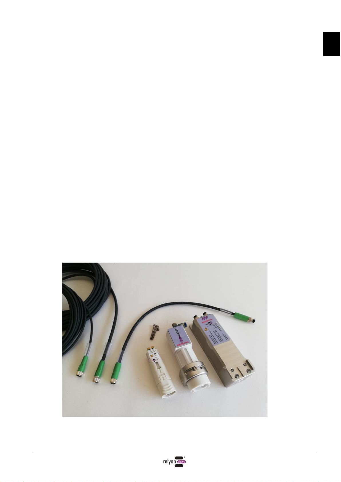
2.2 Scope of delivery...............................................................................................................................7
2.3 Description of device.........................................................................................................................8
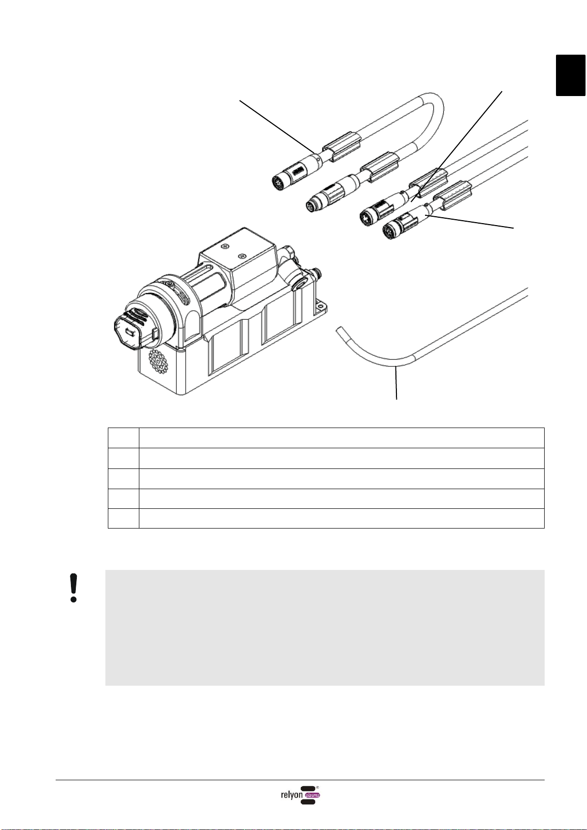
2.4 Connecting lead assignment.............................................................................................................9
3Technical data.........................................................................................................................11
4Transport / storage .................................................................................................................11
5Installation...............................................................................................................................12
5.1 Unpacking .......................................................................................................................................12
5.2 Installation requirements.................................................................................................................12
5.3 Positioning the components............................................................................................................12
5.4 Mounting the components...............................................................................................................14
5.5 Connecting the gas supply..............................................................................................................15
5.6 Connecting the connection cable Digital I/O...................................................................................15
5.7 Adjusting the module carrier ...........................................................................................................16
6Special note on the operation of the plasma process..........................................................18
6.1 General description.........................................................................................................................18
6.2 Carrying out surface treatment .......................................................................................................19
6.3 Measures to take after the surface treatment.................................................................................19
7Operation.................................................................................................................................20
7.1 LED indicator on driver unit.............................................................................................................20
7.2 Switching signals.............................................................................................................................20
7.3 Error acknowledgement..................................................................................................................20
7.4 Inserting / removing the module......................................................................................................21
7.5 Commissioning a device with digital I/O communication................................................................22
7.6 Working with module “Standard”.....................................................................................................23
7.7 Working with module “Nearfield”.....................................................................................................23
7.8 Working with other modules............................................................................................................23
8Taking out of service ..............................................................................................................24
9Maintenance............................................................................................................................24
9.1 Cleaning..........................................................................................................................................24
9.2 Replacing a module ........................................................................................................................24
10 Troubleshooting .....................................................................................................................25
11 Environment............................................................................................................................26
11.1 Disposal ..........................................................................................................................................26
12 Conformity / standards...........................................................................................................26
12.1 CE ...................................................................................................................................................26
12.2 FCC.................................................................................................................................................26
12.3 Product standards...........................................................................................................................27
13 Spare parts..............................................................................................................................27

EN
4
BA-PZ3_i_ML / F0354900
beta-test / preliminary
1Safety
This device is built according to corresponding international standards. Like with every
technical product incorrect or not intended use can however be dangerous.
Follow the instructions in this operating manual in addition to the general safety regulations.
Caution - Danger!
When working with the device, please note and observe the safety instructions and
requirements in these operating instructions because non-compliance may result in
serious or fatal injury.
1.1 Residual risks
This device has been manufactured in accordance with the current state of the art.
However, it is impossible to eliminate residual risks.
Always adhere to the following safety instructions:
Caution –Electrical voltage!
The IEC protection class of this device is class III.
- Only electricians may connect the electrical wiring
- Only use SELV/PELV power supplies
- Let a qualified person check, if the requirements of the basic protection and the
error protection according DIN VDE 0100-410 are fulfilled.
Danger from electrical voltage. If the wiring is visibly damaged:
- Do not use the damaged part.
- Have the damaged parts repaired by a qualified person or replace them.
Danger from sparks on the piezo element and the substrate to be treated:
- Do not reach into the area of the plasma discharge.
- Electrically conductive substrates must be grounded or protected against touching.
- Use air or nitrogen as working gases only! Do not use flammable working gases!
- Flammable or thermal sensitive materials could be ignited or damaged. Check the
compatibility of the plasma treatment before. Never treat flammable materials
unattended.
Trip hazard!
Lay the connection cables and gas pipes in suitable cable trays. Lay cables such that they
do not present a trip hazard.

EN
BA-PZ3_i_ML / F0354900
beta-test / preliminary
5
Attention –Emissions!
Dangerous amounts of the reaction gas ozone (O3) may be produced during device
operation.
- Volumes of ozone in excess of 0.2 mg/m³ may be produced.
- Note that national health and safety measures must be observed when operating
the device.
- Only use the device in well ventilated areas or in conjunction with a suitable
extraction device.
- Do not leave the device running unattended.
- Do not point the device at people when in operation.
- In order to rule out the possibility of dangerous amounts of ozone being produced in
the event of a failure of the extraction system, we recommend monitoring the
extraction power in the process and only enabling plasma generation when the
extraction system is active.
- Due to the corrosive effect of ozone we recommend to place a suitable gas
extraction as close to the nozzle outlet as possible to avoid corrosion/damage of
other devices/surfaces.
Attention –Damage to device!
The plasma generator may be damaged if it is operated without gas flow.
This would interrupt the supply of cooling medium required in operation.
Monitor the gas flow and stop the device immediately if insufficient gas flow is
detected.
Never touch the piezo element at the front of the device with sharp-edged objects. This
component may be damaged by improper handling.
Protect the device from falls or other hard impacts which may damage the electronics or
piezo element.
Caution –hot surface!
The exchange modules can become hot during operation. Do not touch them until they
have cooled down and take care not to damage thermally sensitive surfaces when working
with the exchange modules.
The workpiece to be treated can also heat up during the plasma process, depending on the
process parameters. If necessary, allow the workpiece to cool down before touching it.
Attention! Device for use in industrial environment
Due to the presence of both conducted and radiated interference, this device may have
difficulty in ensuring electromagnetic compatibility in other environments.

EN
6
BA-PZ3_i_ML / F0354900
beta-test / preliminary
1.2 Information and obligations for the operator
•The system may emit interference.
- The system will be tested in accordance with EMC legislation.
- The operator must verify and assure electromagnetic compatibility with other
electrical and electronic equipment in the immediate vicinity of the system.
•Ensure that:
- Operating personnel have read and understood these operating instructions.
- Anyone working near the device is made aware of the dangers and is provided with
the necessary protective equipment.
- Repairs are only carried out by qualified persons.
•In particular, make operating personnel aware of the safety instructions in this
document.
•Always keep the system in fully functional condition.
•Any modifications made to the device will invalidate the operating license and the
warranty. Exception: Such modifications are expressly authorized by the manufacturer.
1.3 Impermissible operating conditions
The device must not be operated under the following conditions:
•In explosive (Ex) zones
•In areas with severe build-up of dust
•In environments where the humidity is too high (see chapter 3)
•At altitudes of more than 2.000 m above sea level
•Where there are strong vibrations
1.4 Emissions
The connected device produces the following emissions:
•Ozone (O3)
•Nitrous gases (NOx)
Process gas
Gas flow
Emission/production rate
Air (CDA)
10 l/min
Ozone < 0,1 g/h
Air (CDA)
10 l/min
NO2 < 5 mg/h
Air (CDA)
10 l/min
N2O< 1 mg/h
Note!
As a precautionary measure, we recommend an extraction system with about 10-times
the flow rate of the entire gas flow through the device (or the devices) in the direct vicinity
of the plasma outlet.
To avoid the possibility of dangerous amounts of ozone being produced in the event of a
failure of the extraction system, we recommend monitoring the extraction power in the
process and only releasing the plasma generation when the extraction system is active.

EN
BA-PZ3_i_ML / F0354900
beta-test / preliminary
7
2Description of device
2.1 Intended use
The piezobrush® PZ3-i is an integration unit for generating technical plasma. It is
intended to be mounted in stationary machines or in positioning units and is used for
pre-treating various material surfaces prior to process steps such as adhesive
bonding or printing. The cleaning effect of the plasma can also be utilized.
Only use the device for the intended purposes. Failure to do so may restrict product
liability.
2.2 Scope of delivery
piezobrush®PZ3-I integration unit (1000 7000 00)
The scope of delivery includes the following components:
•Plasma generator/Integration unit
(consisting of driver unit and module carrier)
•Connection cable between driver unit and module carrier (length 0,3 m)
•Connection cable DC (length 10 m)
•Connection cable communication (length 10 m)
•Module “Standard”
•Module “Nearfield”
•Mounting screws (2 pcs M3x30; 1 pc M3x6)
•Operating instructions
Not included:
•Power supply
•Gas hose (outer diameter of hose Ø 4 mm)

EN
8
BA-PZ3_i_ML / F0354900
beta-test / preliminary
2.3 Description of device
The individual parts of the device are shown and named in the diagram below. These terms
are used throughout the operating instructions.
No.
Component description
1
Module “Standard”(inserted)
2
Piezo element in module (embedded in module)
3
Integration unit (module carrier)
4
Integration unit (driver unit)
5
Fan outlet (cooling driver unit)
6
Fan inlet (cooling driver unit)
7
Interface “Digital I/O“
8
Interface “Module out“
9
Interface “DC in“
10
Interface “Module in“
11
Interface “Gas in“
12
LED status indicator (3 LEDs: Plasma / Warning / Error)
13
Alignment screw for module carrier
14
Mount for module carrier
15
Module “Nearfield”(not inserted)
16
Equipotential bonding terminal
1
2
3
15
4
5
6
10
14
7
11
8
9
12
13
16

EN
BA-PZ3_i_ML / F0354900
beta-test / preliminary
9
Attention!
The piezo element is an oscillating component that vibrates mechanically at high
frequency. Due to its design, this component cannot be fixed rigidly. For this reason, the
component can lie off-center in the interchangeable modules within certain limits. This is
not an error or quality defect.
Due to the vibration, audible frequencies may also occur under certain circumstances.
This is also normal and not a fault or quality defect.
No.
Component description
17
Connection cable module carrier (8-pin, length 0,3 m)
18
Connection cable DC (3-pin, length 10 m)
19
Connection cable communication (6-pin, length 10 m)
20
Gas hose Ø4 mm outer diameter (not included)
20
18
17
19

EN
10
BA-PZ3_i_ML / F0354900
beta-test / preliminary
2.4 Connecting lead assignment
The connections of the connection cable DC are to be assigned as followed:
#
Colour
Signal
1
brown
24V DC
3
blue
GND
4
-not connected-
The connections of the connection cable communication are to be assigned as
followed:
#
Colour
Signal
1
brown
Plasma on (Input 0 to 10 V
analog, up to 24V)
2
white
Plasma OK (Outlet 0V / 24V at
max. 20mA)
3
blue
Error (Outlet 0V / 24V at max.
20mA)
4
-not connected-
5
grey
GND
6
-not connected-
Caution –electrical voltage!
The wires may only be connected to the power supply unit or control system
by authorised electrically skilled persons!
Danger due to line voltage. If the power supply unit is visibly damaged:
- Do not start up the machine.
- Replace the damaged parts or have them repaired by a qualified person.

EN
BA-PZ3_i_ML / F0354900
beta-test / preliminary
11
3Technical data
Electrical data
•Supply voltage
24 V DC
•Power consumption
max. 18 W
•Model
Integration unit with gas connection
Dimensions
•Weight
350 g (with module, without connection cables)
•Dimensions
40 x 157 x 71 mm (BxHxT)
•Cable length
10 m (connection cables)
Typical application parameters (exemplary for module “Standard”)*
Application
Fine cleaning
Bonding
Printing
•Plasma temperature
< 50 °C
•Treatment distance
2 –10 mm
•Width of treatment
Air/CDA 5 - 29 mm, Nitrogen 5 to 50 mm
•Treatment speed
1-15 mm/s
10-150 mm/s
100-1500 mm/s
Operating conditions
•Air humidity
< 80 % rel. (non-condensing)
•Temperature
10 –40 °C; 50 –104 °F
Storage conditions
•Air humidity
< 80% rel. (non-condensing)
•Temperature
0 –60 °C; 32 –140 °F
Gas connection
•Gas types
Compressed air (purified, oil- and lubricant-free)
Nitrogen (particle- and oil-free technical gases)
Additional gas types only after approval from relyon plasma.
•Gas flow rate
10 –25 l/min
•Quality
Compressed air 1.4.1 in accordance with ISO 8573.1
Nitrogen 2.8 (N2) in accordance with DIN EN ISO 14175:N1
•Connection
Hose outer diameter Ø 4 mm (quick coupling)
* These values are only a course guideline. Depending on treated material, process parameters,
following processes and process requirements the actual results can vary significantly from the
typical parameters in both directions (see chapter 6). Due to the low plasma temperature of
lower than 50 °C a slower treatment is not considered critically.
4Transport / storage
•Store the device in a dry place. This will prevent corrosion of the electrical
contacts.
•Protect the device from dirt and foreign objects.
•Protect the device from falls or other hard impacts.

EN
12
BA-PZ3_i_ML / F0354900
beta-test / preliminary
5Installation
Attention - Damage to device!
In order to prevent damage to the device, please ensure that you follow the advice in
chapter 7.
5.1 Unpacking
•Carefully open the packaging. Note the information about directions provided on the
packaging.
•Remove the device from the packaging.
5.2 Installation requirements
Before installing the machine, the following must be true:
•The machine must be fully intact.
•Provide a power supply (SELV/PELV) that meets the following requirements
- Output Voltage: 24V +/- 5%
- Output Ripple: <1%
- Power supply: min. 18 W per device
•There must be an appropriate gas supply (see chapter 3).
•If installing as a permanent installation or in a building, a suitable switch or circuit
breaker that satisfies national safety requirements (in Germany: VDE 0100) must be
fitted as an upstream all-pole cut-off device that will disconnect the machine from the
power supply. This cut-off device should be fitted near the machine and must be easily
accessible to the user. The switch must also be labelled as the cut-off device for the
machine.
5.3 Positioning the components
The following points must be observed when positioning the device:
- The distance between the piezo elements must be at least 40 mm from center to
center.
- In the area of the foremost quarter of the piezo element, no electrically conductive
objects may be positioned laterally closer than 40 mm.
- position a gas extraction close to the plasma discharge. Note that ozone is a
corrosive gas and the extracted gas stream can also corrode varnished surfaces. Also
note point 1.4 for the extraction quantity.
- Make sure that the fan openings on the top and bottom of the unit are not covered.
- Avoid permanent movement of the cables.
In the beta test status, the robot and drag chain suitability has not yet been
conclusively tested. To avoid damage, we currently recommend avoiding permanent
cable movement. A corresponding specification is planned for the series production
status.

EN
BA-PZ3_i_ML / F0354900
beta-test / preliminary
13
- The device must either be positioned in such a way that the exchange module can be
pulled out of the module carrier during maintenance or, alternatively, in such a way that
the module carrier can be removed as described in 7.4.
- Three M4 holes as shown in the drawing below are required for mounting the device.
The keyway (DIN 6885-A1, 3x3x8) is optional (for high demands on the repeatability of the
positioning; e.g. for multi device solutions).

EN
14
BA-PZ3_i_ML / F0354900
beta-test / preliminary
5.4 Mounting the components
Fasten the driver unit to your mounting surface first at the top with the enclosed
countersunk screw (M3x6, SW 2) and then at the bottom with the two cap screws
(M3x30, SW 2.5)
Insert the desired module into the module carrier. To do this, hold it from the outside in
the front area as shown in the picture without touching the piezo element. With the sticker
pointing upwards, the module can simply be inserted into the module carrier. Make sure
that the module is inserted as far into the carrier as shown in the picture.
Place the module carrier onto the driver unit by positioning it flat above the interface and
then sliding it down until the stop.

EN
BA-PZ3_i_ML / F0354900
beta-test / preliminary
15
5.5 Connecting the gas supply
Connect a suitable gas hose with an outer diameter of Ø 4mm. Press it as far into the
push-in fitting until it is locked. Check the tight fit of the hose before applying pressure to
it. If you are using the device without gas flow monitoring, you can achieve a flow rate of
10 l/min using the following characteristic curve by adjusting the inlet pressure and your
hose length:
5.6 Connecting the connection cable Digital I/O
Connect the connecting cable between module and driver unit. In the following, tighten all
union nuts hand tight.
Connect the communication connection cable to the driver housing.
Connect the DC connecting cable to the driver housing.
Connect the potential equalization to the ground potential.
piezobrush® PZ3-i: inlet pressure setting for 10 l/min gas flow
Length of gas hose Ø4 mm [m]
inlet pressure [mbar]

EN
16
BA-PZ3_i_ML / F0354900
beta-test / preliminary
5.7 Adjusting the module carrier
•Height adjustment
The module carrier can be adjusted in height via the adjustment screw.
Loosen it and move the module carrier to the desired height. Tighten the screw
again in this position.

EN
BA-PZ3_i_ML / F0354900
beta-test / preliminary
17
•Angle adjustment
In the vertical axis, the module carrier can be rotated by +/- 45° relative to the driver
housing.
To do this, loosen the adjustment screw so far that the screw head can be moved
over the countersinks in the cut-out.
The predefined angles are - 45°, - 31°, 0°, + 31° and + 45°.
Due to its design, the piezo element does not have a circularly symmetrical cross-
section. The discharge shape results in optimum angles for activation results that
are as homogeneous as possible.
Depending on the direction of movement of the device relative to the substrate to be
treated, the angle adjustment can thus be optimized for high homogeneity
requirements.
•Sealing sticker
To prevent accidental change of these settings, the adjustment screw can be
covered with the enclosed sealing sticker. A module change can be made without
tools and without changes to the positioning of the module carrier.
-45° -31° 0° 31° 45°

EN
18
BA-PZ3_i_ML / F0354900
beta-test / preliminary
6Special note on the operation of the plasma process
6.1 General description
Treating surfaces with atmospheric pressure plasma has several advantages. These are
e.g. the increase of surface energy to improve the wettability of the surface. An optimal
surface wetting is the first and often decisive step to achieve excellent print quality,
homogeneous coating, uniform varnishing or an integrally bonded application of
adhesives. The bond at this interface often determines the durability and adhesive
strength of this material pairing.
Atmospheric pressure plasma increases throughput in many industrial processes, while
at the same time saving costs for solvents or chemical primers. We have successfully
integrated our plasma products into the following fields of application:
•Ultra-fine cleaning of metal, glass and plastics
•Surface activation and surface functionalization for optimized wettability
•Plasma-assisted laminating process
•Plasma-assisted adhesive bonded joints
•Plugging and sealing
•Plasma induced reduction of metal surfaces
•Chemical-free bleaching of textiles
•Handling of food products for quality and shelf life
•Multi-component injection molding
Practically all technical material classes can be efficiently processed under atmospheric
pressure:
•Metals and metal alloys
•Plastics and composite materials
•Glass, ceramics, inorganic composites and natural stone
•Real leather and imitation leather
•Natural fibers, wood and paper
Since the plasma treatment is always just one part of the entire process, it is important to
know the overall influences on the surface properties in order to achieve an optimal result.
Typical influencing factors are:
•Plasma process: Distance to the substrate, speed, power setting, gas type
(CDA/Nitrogen), gas flow, module design
•Substrate / workpiece: Material composition, contamination, electrical conductivity,
thermal conductivity, moisture content
•Workpiece treatment: Contamination before or after the plasma process, the time
between the plasma process and the follow-up process
Treatment examples can be requested directly from relyon plasma GmbH.
Please note that the selected plasma system is suitable for the desired application.
Additional information on applications, as well as publications, can be found on the
website www.relyon-plasma.com.

EN
BA-PZ3_i_ML / F0354900
beta-test / preliminary
19
6.2 Carrying out surface treatment
Depending on the type and condition of your substrate, pre-cleaning before the plasma
process can improve the overall outcome.
The effect of the treatment depends on the working distance, treatment time, speed
and consistency of movement as well as the material to be treated.
Treatment examples can be requested directly from relyon plasma GmbH.
6.3 Measures to take after the surface treatment
To achieve an optimal result, it is important that as little time as possible elapses after
the plasma treatment and that the treated surface is not touched or contaminated.
Cleaning the surface AFTER the plasma treatment is not recommended.
Since the workpiece can heat up depending on the type and duration of the plasma
process, it may be necessary to allow the workpiece to cool down first before the next
process step is executed in order to not negatively affect the follow-up process through
the introduction of heat (e.g. certain bonding processes).
Caution –Hot surface!
The workpiece to be treated can become heated up by the plasma process depending on
the process parameters. If necessary, allow the workpiece to cool down before handling it.

EN
20
BA-PZ3_i_ML / F0354900
beta-test / preliminary
7Operation
7.1 LED indicator on driver unit
In the event that the "Error" signal is present due to an error condition, the cause of the
error can be limited via the LED display on the driver housing using the following error
codes:
7.2 Switching signals
•Plasma on
Analog input to start the plasma generation.
By signal voltage between 3 V and 10 V the
power can be controlled as follows.
The voltage value for the desired power
must be permanently present for the
duration of the plasma generation.
•Plasma OK
Output with feedback about the plasma state.
In a permissible operating state, 24 V are present at this output. In a switched-off state or
in the event of a fault, 0 V are present. Maximum load 20 mA.
•Error
Output with feedback on the error status. In the event of an error, 24 V are present at
this output. In permissible operating states, 0 V are present. Maximum load 20 mA.
7.3 Error acknowledgement
The error status remains active even after deactivation of the "Plasma on" signal.
Acknowledgement of the error after removal of the problem, can only be done by
removing the 24 V voltage supply on the DC connection line.
To restart plasma generation, the "Plasma on" switching signal must be switched on
again.
Voltage
Power setting
0 V
plasma off
3 V
30 %
4 V
40 %
…
…
10 V
100%
>10 V (up to 24 V)
100%
Device not powered
Device ready
Device powered; no module detected
Plasma process running
Warning: plasma process running, plasma critical
Warning: plasma process running, temperature critical
Failure: plasma
Failure: temperature
Legend:
off
permanent light
flashing (quantity)
Other manuals for relyon plasma piezo brush PZ3-i
1
Table of contents
Other TDK Industrial Equipment manuals
Popular Industrial Equipment manuals by other brands

Viking
Viking VFT Installation, operation and maintenance manual

Prism Hardscapes
Prism Hardscapes PH Ignite Instruction, Operation & Maintenance

Siemens
Siemens 3VA944 0KP00 Series operating instructions

Renishaw
Renishaw OMP40-2 installation guide

LNS
LNS Hydrobar Express 332 Startup manual

Weh
Weh TW221 operating instructions