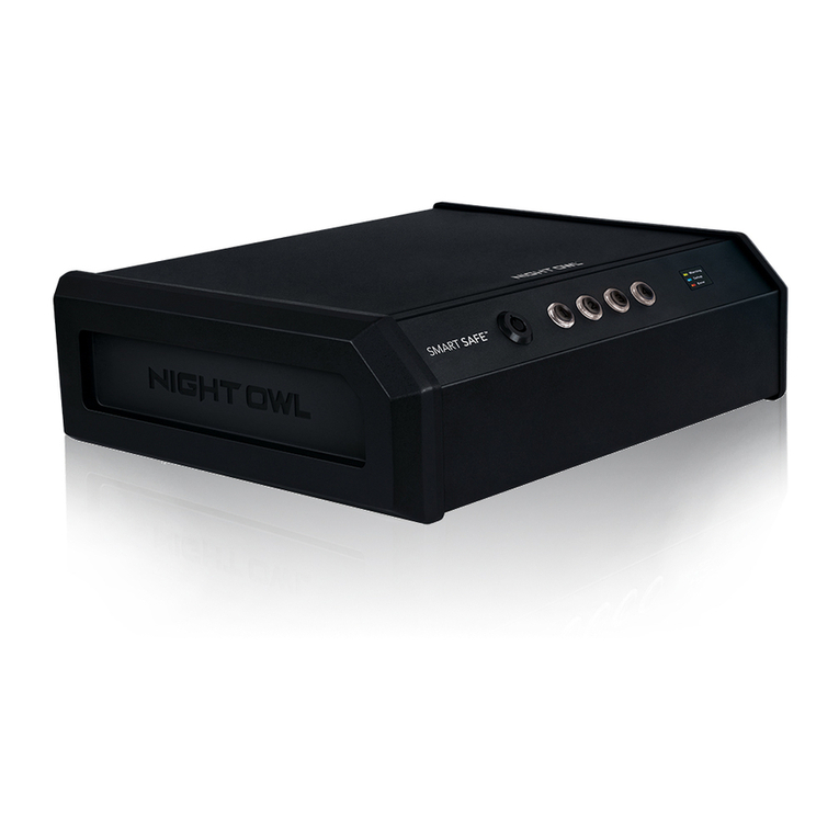
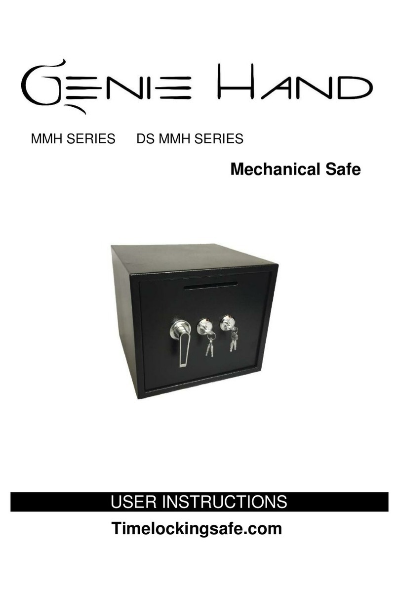
TDL Triton VersaSafe Operating instructions

1
VersasafeTM InsTallaTIon
Versasafe™
PreParation and installation
TDN 07103-00335 May 17, 2012
CorPorate Headquarters:
21405 B Street
Long Beach, MS. 39560
Phone: (800) 259-6672
FaX: (228) 868-9445
© 2012 Triton. All Rights Reserved. TRITON logo is a registered trademark of Triton
Systems of Delaware, LLC.

2
VersasafeTM InsTallaTIon
WHat’s in tHis installation
Guide
This Installation Guide provides information for the physical installation of the VersaSafe™. It contains requirements for site prepa-
ration, electrical specications, and cabinet accessibility that comply with all relevant codes, laws and regulations. The Installation
Guide is divided into the following sections:
site ComPlianCe. States the customers responsibilities for ensuring all relevant regulations are adhered to.
Versasafe™ enVironmental PreCautions CHeCklist. Describes the general environmental precautions considered when
installing the VersaSafe™. To help ensure proper operation of the unit, ensure the environmental criteria listed in this checklist
are met.
dimensions. Describes physical dimensions for the cabinet(s), and control panel components.
- Physical dimensions.
-Service area dimensions.
-Customer access dimensions
installation. Describes anchoring the cabinet using standard (steel) or the optional chemical anchors. (Anchors provided
separately)
PoWer and CommuniCation. Shows cable access area, power requirements, and powering-up the unit.
introduCtion
The Triton VersaSafe™ is an automated cash receptacle and depository designed for indoor use only. The following sections provide
the requirements for installing the VersaSafe™ for your particular site location. To assist you in preparing your site, a check list is
provided of various steps that should be carried out prior to the arrival of your unit.
site ComPlianCe ............................................................................................... ............................................3
enVironmental PreCautions ........................................................................ ............................................4
teMPerature / Power / rF InterFerence requIreMentS ................................................. .....................................................4
dimensions ......................................................................................................... ............................................5
caBInet anchor “FootPrInt” ................................................................................................... ..........................5
DeeP caBInet Front VIew / cuStoMer acceSS DIMenSIonS / SIDe / toP ................. ............................................5
weIght .................................................................................................................... ............................................5
Cabinet installation................................................................................................................6
tooLS requIreD . ................................................................................................................................................6
unPackIng the unIt ...........................................................................................................................................6
Mark / DrILL MountIng hoLeS ...........................................................................................................................7
InStaLLIng StanDarD anchorS / Secure caBInet ................................................................................................8
InStaLL cheMIcaL anchorS / Secure caBInet ............................................................ ........................................9
route PoWer / CommuniCation Cables..................................................................................12
route / connect caBLeS/InStaLL tDL gateway ..............................................................................................12
oPtional PlintH installation.................................................................................................14
aPPendix....................................................................................................................................15
installation Contents

3
VersasafeTM InsTallaTIon
This document contains the information necessary for the preparation and installation of a Triton VersaSafe™. It’s impor-
tant that the site complies with the requirements specied in this document. In addition, electrical wiring and mechanical
systems must also comply with all relevant laws and regulations.
The site must be prepared by the customer or his agent who is fully conversant with the requirements of installing elec-
tronic equipment. The responsibility for ensuring that the site is prepared in compliance with this document remains with
the customer.
For information and guidance only, a list is provided in general terms of those matters for which the customer is responsible.
The list is not intended to be comprehensive and in no way modies, alters, or limits the responsibility of the customer
for all aspects of adequate site preparation.
1. Location of the equipment and site preparation. Ensure the site selected minimizes the possibility of liquid or food
spills.
2. Site wiring (power, communication). Ensure access will not be hindered by cabinet placement.
3. Location of other equipment that may cause electrical, electromagnetic or heat induced interference.
4. Make building alterations to meet wiring and other site requirements.
site ComPlianCe
SITE PREPARATION CHECKLIST
1. Select site and design oor plan accordingly
2. Ensure all environmental conditions are met
3. Establish contractor and vendor schedules
4. Check communication line requirements
5. Plan installation and accessory needs before
starting
6. Check oor plan and make necessary altera-
tions
7. Install all required electrical xtures
8. Prepare site for communications needs
9. Plan operator/training exercises (optional)
10. Install communication lines and test
11. Ensure installation accessories are available
5. Install all communication cables, wall jacks, and associated hardware.
6. Provide and install necessary power distribution boxes, conduits, and
grounds.
7. Ensure all applicable codes, regulations, and laws (electrical, building,
safety) are adhered to.
8. Ensure the environmental requirements of this unit are met.

4
VersasafeTM InsTallaTIon
When installing a VersaSafe™, some general environmental and power precautions must be consid-
ered. Evaluate the location where the unit will be installed. To help ensure proper operation of the
unit, ensure the environmental criteria listed in this checklist are met.
netWork ConneCtiVity
(Wireless oPtional)
3. Ensure the following network requirements are
met:
Proximity to Interference Sources. The network
connection must not be in close proximity to “noisy”
devices that could induce interference into the units
communications channel. See the next section for ad-
ditional information on “interference sources.” Wireless
communications also available. Antenna placement is
critical.
rf interferenCe
4. Ensure there are no devices near the terminal
that may cause RF interference, such as:
TVs
Coolers
Security devices
Neon signs
Devices with compressors or motors.
* IMPORTANT *
AC power for the terminal should
come from a dedicated source with an
isolated ground.
Dedicated source. The VersaSafe™ AC power feed will
be a dedicated line, to which no other electrical devices
are connected. The VersaSafe™ power line will be
wired for a single “duplex”-style outlet and connected
directly to the AC service panel. (No extension cords)
Isolated Ground. An equipment grounding conduc-
tor that is insulated from the conduit or raceway and
all other grounding points throughout its entire length.
The only points of electrical connection will be at the
duplex outlet and service panel ends of the line.
temPerature / Humidity
1. The VersaSafe™ will operate over a range of
temperatures and humidity. Generally, these
parameters must fall within the following ranges:
Temperature
• 10°C to 40°C
• 50°F to 104°F
Relative Humidity
• 20% to 80%
• (Non-Condensing)
aC PoWer requirements
2. Ensure the following AC power requirements
are met:
Current (Max)
• 2.2A @ 115 VRMS at 60 Hz
• 1.1A @ 230 VRMS at 50 Hz
Voltage
• 90 - 136VRMS @ 50/60 Hz
• 198 - 257VRMS @ 50/60 Hz
Power Consumption (Idle)
• 0.6A @ 115 VAC at 60 Hz
• 0.3A @ 230 VAC at 50 Hz
Power Consumption (Max Load)
• 250 Watts @ 120VAC
• 250 Watts @ 240VAC
Surge ~50A @ 230V
enVironmental PreCautions
VersaSafe™ is designed for indoor use only.

5
VersasafeTM InsTallaTIon
serViCe area dimensions Cabinet “footPrint”
Anchor “footprint” -
FRONT
SIDE
TOP
Allow sufcient extra
space around the front
and sides as necessary
for access. Unit shown
with Bill Acceptor
bracket extended. En-
sure there is adequate
room for the door to
swing open.
DO NOT be tempted to place the cabi-
net on a table or other support. Severe
injury and equipment damage will oc-
cur if the support fails. Not attaching
the cabinet to the oor compromises
security.
PHysiCal dimensions
WEIGHT
Deep cabinet 400 lbs
dimensions/sHort Cabinet

6
VersasafeTM InsTallaTIon
dimensions/deeP Cabinet
PHysiCal dimensions

7
VersasafeTM InsTallaTIon
Cabinet installation
The following procedure applies to installing the cabinet assembly using either standard (P/N 06200-00066) or chemical (06200-00060)
anchor kits. The anchor kits are not supplied with the unit, but are available from Triton.
1. Carefully inspect the shipping container for any damage and report any damage
immediately to the shipping company. Refer to the warranty information at the
end of this manual for information about reporting shipping damage.
2. Remove the VersaSafe™ cabinet from the carton by cutting the straps and
removing the top of the box.
3. Remove the packing material from inside of the box.
4. Remove silver key from white plastic bag attached to the VersaSafe™ wrapping.
* imPortant *
Model VersaSafe™ is designed for INDOOR use only!
unPaCk Versasafe™
5. Remove the remainder of the box from the unit if necessary.
6. Remove the wrapping from the unit.
7. Turn the handle under the electronic lock to open the front enclosure door. If the
door is locked, see sidebar on this page for help in unlocking electronic lock.
8. Remove the packing material from inside the vault enclosure.
9. The accessory box is shipped inside the cabinet enclosure. Open and inspect the
contents. Check the contents against the enclosed packing list and report any
missing parts to Triton. Ensure you locate the whip antenna, if wireless TDL
Gateway modem is installed.
10. Remove the 4 (four) bolts and or nuts retaining the unit to the pallet.
UNLOCKING
COMBINATION LOCKS
Electronic Lock. The combination of the
lock is preset to 1-2-3-4-5-6. To unlock, enter
the preset combination and check for proper
operation. After each keypress, the lock will
‘beep’. After the nal digit has been entered,
the lock will beep twice, and the open period
begins. When a valid combination has been
entered, the operator will have approximately
3 seconds to open the lock. To open the lock,
turn the outer ring of the dial clockwise.
After the lock is opened, the vault door may
be opened.
Optional Kaba Lock. The combination of
the lock is preset to 5-0-2-5-5-0. To unlock,
spin the dial to the left until the letters “EC”
appear on the screen. Enter the preset com-
bination. Successful entry will display “OPr”
on the screen. Turn the dial to the right until
the bolt retracts. After the lock is opened, the
vault door may be opened.
TOOLS REQUIRED
Torque wrench, adjustable to at least 60 foot pounds, adjustable crescent, or
ratchet wrench.
Center punch (or equivalent) for marking drill holes
Hammer 3/4” (19mm) socket Large at screwdriver
Bubble level 7/16” socket/box wrench Safety goggles
Hearing pro-
tection
1/4” (6mm), 1/2” (12mm), and 8/16”
(15mm) carbide-tipped 6” masonry bits
3/4” heavy=duty electric drill
(rotary hammer)
Back sup-
port belt
Portable vaccuum cleaner or air blower Wire brush
Standard Anchor Kit (part no: 06200-00066)
1/2” at washers, 1/2” x 4 1/2” sleeve-type anchor bolts, 1/2” nuts
Chemical Anchor Kit (part no: 06200-00060)
Call for ATMGurus for availability (1-888-728-6487)

8
VersasafeTM InsTallaTIon
CONCRETE STRENGTH
The oor at the installation location should
consist of commercial-grade concrete
measuring at least 2000 psi in compres-
sion strength. The full effectiveness of
the mounting anchors depends upon
meeting this specication! Check with
the contractor/builder or owner of the
installation to verify that this requirement
can be satised.
SELECTING THE
INSTALLATION LOCATION
Choosing the right location for your
unit is very important. Security con-
cerns suggest a location that is away
from any door or external access point.
Ideally, the terminal should be mounted
as close to a back wall as possible.
Wherever you decide to locate the
terminal, be sure to follow the recom-
mended procedures for both mounting
the unit.
Mark the location of the cabinet mounting holes on the concrete oor. This is
accomplished as described below, (see gure 1).
1. Move the unit to the location where it will be installed. Open the cabinet vault
door at least 90° to improve access. Locate the four (4) anchor-bolt holes in
the bottom of the cabinet (each corner). Use a felt-tip pen or other marker to
carefully mark the center of each of the four corner holes on the oor; these
marks will serve as guides for the anchor bolt holes that will be drilled in the
next step. Move the unit aside to provide clear access to the mounting hole
marks. Center punch each mark to help align the drill bit.
2. Use a 1/4” [6 mm] diameter carbide-tipped masonry bit to drill four pilot
holes at the drilling points marked in the previous step. Drill the pilot holes
approximately 1/2” [12 mm] deep into the oor. These holes will help guide
the masonry bit that will be used to drill the anchor-bolt holes in the next step.
3. Standard anchors: Use a 1/2” [13mm] diameter carbide-tipped masonry bit
to drill four holes at least 2-3/4” [70mm] deep into the oor. Be sure to take
into account the depth of any oor covering, such as tile or vinyl when gauging
the depth of the anchor holes. Make sure the holes are drilled at least 2- 3/4”
[70mm] into the concrete oor.
3a. Chemical anchors: Use a 9/16” [15mm] diameter carbide-tipped masonry
bit to drill four holes at least 4-1/2” [115mm] deep into the oor. Be sure to
take into account the depth of any oor covering, such as tile or vinyl when
gauging the depth of the anchor holes. Make sure the holes are drilled at least
4- 1/2-inches [115mm] into the concrete oor.
TOOL USE/SAFETY
Observe ALL safety precautions for operat-
ing hand and power tools! Wear eye and ear
protection while operating the electric drill!
mark/drill mountinG Holes
4. Hole Diameter: Ensure the holes drilled are not too large in diameter. Test t
the anchor bolts by hand. They should require hammering, accomplished in
a later step, and not fall into the hole. Its easier to drill the holes larger now if
necessary, than have to move the cabinet and redrill later because they are too
big. DO NOT be tempted to install the anchors now. It is VERY difcult to
position the terminal onto the anchors because of the weight.
5. Use a portable vacuum cleaner or blower to remove dust or debris that may
have fallen into the holes during the drilling process.
Blow or vacuum out dust/debris.
Figure 2
Drill 9/16” anchor holes with carbide-tipped bit.
Figure 1

9
VersasafeTM InsTallaTIon
install standard anCHors
bolt Versasafe™ to floor
1. Ensure the mounting location is free of all debris that might prevent cabinet from leveling.
2 Move the unit into position for mounting by aligning the base over the four holes drilled in the previous procedure.
3 Place an anchor mount through the cabinet base and into one of the mounting holes. Use a hammer of sufcient weight to tap
the mount completely into the hole, (see gure 3, 4)
IMPORTANT: If the anchor mount “falls” into the hole without needing to be tapped in, the hole is too large! The mounting-
hole pattern will have to be moved and redrilled using smaller holes as necessary to achieve a snug t.
Place anchor mounts through cabinet base and into
mounting holes.
Tap anchor mounts into mounting holes.
4. Place a bolt into mount, then place at washer on the anchor bolt followed by
a 1/2” (13mm) nut on top to secure. Do not tighten fully, allow for leveling.
5. Repeat Steps 2 and 3 for the remaining anchor bolts.
6. Ensure the cabinet is as level as possible, given the oor conditions. Use a bubble
level to verify this. Check the need for leveling by rocking the cabinet from side
to side..
7. Use a torque wrench and 3/4” [19mm] socket to tighten each nut to a torque
setting of 60 foot-pounds (required to establish the maximum pull-out strength
of the anchors). If a torque wrench is not available, use a ratchet wrench and
3/4” [19mm] socket to tighten the nuts three full turns beyond hand tight. Do
Not overtighten.
8. Once the nuts are tightened as specied in Step 7, install a second nut on each
bolt, to act as a jam nut, and tighten down rmly.
Figure 3 Figure 4
Figure 5
4 1/2 “ anchor bolt

10
VersasafeTM InsTallaTIon
install CHemiCal anCHors
bolt Versasafe™ to floor
1. Move the unit into position for mounting by aligning the base over the four holes drilled in the previous
procedure. Ensure the area is free of all debris which might cause the cabinet not to be level.
2. Begin by inserting a Chem Stud capsule into one of the mounting holes. Either end of the capsule may be
inserted rst.
3. Place a washer and a nut (in that order) onto a chisel point rod. Thread the nut onto the rod, leaving 3 to 4
threads exposed at the top.
Concrete slab
Insert Chem Stud capsule in mounting hole.
Figure 7
flat WasHer
mountinG nut
loCkinG nut
Figure 6
Anchor bolt conguration
Versasafe base
anCHor bolt slab

11
VersasafeTM InsTallaTIon
10. Ensure the unit is as level as possible given the oor conditions. Use a bubble level to verify
this. If a bubble-level is not available, the cabinet can be “rocked” gently from front-to-back
and side-to-side to check the need for leveling.
11. Use an adjustable wrench or a ratchet wrench with 3/4” [19mm] socket to tighten the nuts
down. No minimum torque setting for the nuts is required. Simply ensure the nuts are
tightened down rmly enough to secure the cabinet to the anchors. Tightening the nuts just
beyond hand tight should prove adequate.
12. Once the unit is square (level), install a second nut on each bolt and tighten down rmly.
Base Material Temperature Setting Time
68o F/ 20o C or above 20 minutes
50o F/ 10o C to 68o F/ 20o C 30 minutes
32o F/ 0o C to 50o F/ 10o C 1 hour
23o F/ -5o C to 32o F/ 0o C 5 hours
14o F/ -10o C to 23o F/ -5o C 10 hours
Figure 7
9. Allow the adhesive to cure for the specied time (see chart and important note, which follows)
prior to applying any load to the anchors. During the winter, the hole temperature may be
different than the room temperature! The hole temperature should be measured to determine
the curing time required. DO NOT disturb or load the anchors until they are fully cured!
(If in doubt wait)
7. Pull the driver out of the coupling while holding the rod. Hold the hex nut with a wrench to
unthread the coupler.
8. Repeat steps 1-7 for each of the remaining mounting holes.
6. Insert the chisel point of the rod into the hole to break the glass capsule. Spin it into the capsule
at a speed of 250 to 500 RPM, until it is fully embedded. IMPORTANT! Turn the rotary
hammer drill OFF IMMEDIATELY when the rod is fully embedded or it will strip out!
4. Thread the rod coupler onto the threaded rod until it is tight against the nut. The threaded rod
used should be free of dirt, grease, oil or other foreign material.
5. Select the drive unit, insert it into a rotary hammer drill and engage the coupling to be used.
Curing times and temperatures

12
VersasafeTM InsTallaTIon
route PoWer and CommuniCation Cable
1. Route the AC power cord and the TCP/IP cable through either the main or alternate cable access hole (as applicable, see gure
1). (Communications capability is limited to a remote computer using Triton Connect and VersaLink)
2. Connect the AC power cord and communication cable to their respective facility outlets.
NOTE: Before you start, unlock and open the control panel. Verify that the power switch on the unit’s power supply is in the off
(0) position. Close the control panel.
3. Secure/plug the unused access hole with the grommet or plug provided.
Power Outlet Accessibility
Whether you are installing a new AC socket outlet or plan to use
an existing outlet to supply power to the VersaSafe™, make sure
the following requirements are met:
1. The outlet is located near the equipment. Extension cords are
not recommended.
2. AC power for the terminal should come from a dedicated
source with an isolated ground. The unit is designed to work
on an IT (Isolated-Terra) type power system having a phase-
to-phase voltage not exceeding 240 volts.
3. The outlet is easily accessible and will not be blocked once
the equipment is installed and anchored.
POWER SUPPLY CORD -
SPECIFICATIONS
For European applications, the power
supply cord must conform to the fol-
lowing specications:
1. Two-conductor with Physical Earth
(PE) ground.
2. IEC 320 molded connector on one
end and molded plug on the other
end.
3. Certied for country of installation.
4. Rated minimum H05VV-F with
minimum 0.75 mm2 (except where
specic countries require 1.0 mm2)
conductors.
5. Maximum length: 3 meters.
Figure 1
Power cable cover
Figure 2
Corner holes allow passage of power, ground and
communication wiring. Wiring to an external mount-
ed antenna will run through the access holes and
connect to the TDL Gateway wireless communica-
tions systems. The USB cable provides power to the
wireless modem.

13
VersasafeTM InsTallaTIon
After nal connection of power and communication, and ensuring the cabinet is secured to the oor
or optional plinths, install the power cable cover, (see gure 2) with the 6 (six) screws provided.
The cover and screws are in the accessory bag. This must be accomplished to ensure the physical
security provided by the VersaSafeTM.
Keep in mind when mount-
ing antenna on outside
of unit that its location
will directly affect signal
strength of the TDL Gate-
way. If a weak signal is
encountered and does not
improve, it may be neces-
sary to obtain a booster
amplier. The amplier
installs between the TDL
Gateway and the antenna
and requires AC power.
Contact Triton technical
support for further details.
A USB cable will connect the wireless modem to the
system’s main board and serve as its power supply.
Use TY wraps to bundle cables if necessary.
The TDL Gateway modem will mount atop the units power supply. A USB cable will provide power
to the unit from the system’s main board, (see gure 3). The antenna will mount atop the VersaSafe
unit with a magnetic holder and the connection cable will run into the cabinet through holes in lower
corner of unit. The cable will connect to the wireless modem with threaded cable, (see gure 4). If
weak signal occurs, a booster amplier may be necessary to aid communications.
Figure 3
The TDL Gateway mounted on top of unit’s power
supply provides wireless communication. Screw on
adaptor connects the modem’s antenna.
Figure 4
Figure 5
NOTE: New VersaSafe units will come pre-loaded with the current 2.4.4 SP5 software. If upgrad-
ing unit, do not plug in TDL Gateway modem until software version 2.4.4 is loaded to system. If
2.4.4 software is not loaded, an error code will result notifying the user that the device is not found.

14
VersasafeTM InsTallaTIon
oPtional PlintH installation
The optional plinth installation kit includes a four and one quarter inch (4 1/4”) tall Plinth, four (4) wash-
ers and four (4) nuts. The plinth is used to raise the VersaSafeTM up off the mounting surface to facilitate
access or ensure no foreign objects, such as water, enter the cabinet.
Installation of the Plinth is the same as the cabinet. Ensure the Plinth is level and all four (4) mounting
points to the oor are secure. Any unevenness in the Plinth will be multiplied with any additional height.
Ensure the four (4) mounting points between the VersaSafeTM and the Plinth are secure. Do not be tempt-
ed to use less than the four (4) pieces of hardware supplied. If more than one Plinth is used, ensure all
mounting hardware is secure. Use no more than two plinths. Once installation is complete, restore power
and test functionality. See operations manual TDN 07103-00336 for set up.
CAUTION !!!
THE VERSASAFETM IS VERY HEAVY, APPROXIMATELY 400 POUNDS. USE EXTREME
CAUTION WHEN LIFTING THE VERSASAFETM ONTO THE PLINTH. IF MORE THAN
ONE PLINTH IS USED, ENSURE YOU HAVE ENOUGH ASSISTANCE TO RAISE THE
VERSASAFETM. BE ESPECIALLY MINDFUL OF PINCHED FINGERS. DO NOT PUT
YOUR FINGERS UNDER THE VERSASAFETM.
TOOLS REQUIRED
Optional Plinth (part no: 06100-08204)

Appendix A
SoftwAre LicenSe Agreement
compLiAnce / emiSSion StAtementS
A-1

A-2
Appendix A
AutomAted teLLer mAchine (“Atm”) SoftwAre
end-uSer Agreement
importAnt: pLeASe reAd cArefuLLY:
BY INSTALLING OR OTHERWISE USING THE ATM, YOU (AS THE OWNER OR LESSEE OF THE ATM).
AGREE TO BE BOUND BY THE FOLLOWING TERMS AND CONDITIONS, INCLUDING, WITHOUT
LIMITATION, THE WARRANTY DISCLAIMERS, LIMITATIONS OF LIABILITY AND TERMINATION
PROVISION WHICH APPLY TO YOUR USE OF THE ATM SOFTWARE CONTAINED IN THIS ATM AND
IS HEREBY LICENSED BY TRITON SYSTEMS OF DELAWARE, INC. (“Triton”) TO YOU PURSUANT
TO THIS AGREEMENT.
IF YOU DO NOT AGREE TO OR ARE NOT WILLING TO BE BOUND BY THE TERMS AND CONDI-
TIONS OF THIS AGREEMENT, DO NOT INSTALL OR OTHERWISE USE THIS ATM AND PROMPTLY
CONTACT YOUR VENDOR. INSTALLING OR OTHERWISE USING THE ATM INDICATES THAT YOU
ACCEPT THESE TERMS.
This ATM is manufactured by, and utilizes proprietary software owned by Triton Systems of Delaware, Inc.
and/or its suppliers. All right, title and interest in and to all component software installed or embedded in the
ATM (“ATM Software”) including all associated intellectual property rights, are and will remain the property
of Triton and/or its suppliers.
LICENSE: Triton grants you a limited, nonexclusive license to use the ATM Software but only in connection
with the operation of this ATM subject to the terms and restrictions set forth in this License Agreement. You are
not permitted to use the ATM Software in any manner not expressly authorized by this License. You acknowl-
edge and agree that ownership of the ATM Software and all subsequent copies thereof regardless of the form or
media are held by Triton or its suppliers.
The software is licensed for use on this specic Triton ATM product and may not be used on any other product.
Otherwise, the supporting documentation, if any, may be copied only as essential for backup or archive pur-
poses in support of your use of the ATM. You must reproduce and include all copyright notices and any other
proprietary rights notices appearing on any copies that you make.
ASSIGNMENT: NO REVERSE ENGINEERING: You may transfer the ATM Software to another party
but only in connection with a transfer of all your right, title and interest in and to this ATM and if such party ac-
cepts the terms and conditions of this License Agreement. If you transfer the ATM, you must at the same time
transfer the supporting documentation, if any, to the same party or destroy any such materials not transferred.
Modication, reverse engineering, reverse compiling, or disassembly of the ATM and/or the ATM Software is
expressly prohibited.

A-3
SoftwAre LicenSe Agreement / compLiAnce/emiSSion StAtementS
DISCLAIMER OF WARRANTIES AND LIMITATION OF DAMAGES
TO THE EXTENT PERMITTED BY LAW, THIS ATM SOFTWARE, INCLUDING ALL INCORPORATED
THIRD PARTY SOFTWARE, AND DERIVATIVES IS PROVIDED, “AS IS”. TRITON MAKES NO REPRE-
SENTATIONS WITH RESPECT TO, AND DOES NOT WARRANT THE PERFORMANCE OR RESULTS YOU
OR YOUR CUSTOMERS MAY OBTAIN BY USING THE ATM. TRITON SPECIFICALLY DISCLAIMS ANY
AND ALL WARRANTIES, EXPRESS, IMPLIED OR STATUTORY, INCLUDING WITHOUT LIMITATION,
WARRANTIES OF QUALITY, PERFORMANCE, NONINFRINGEMENT, AND MERCHANTABILITY OR
FITNESS FOR ANY PARTICULAR PURPOSE.
TRITON MAKES NO REPRESENTATIONS OR WARRANTIES AND ASSUMES NO OBLIGATIONS TO
YOU OR YOUR CUSTOMERS WITH RESPECT TO ANY TRANSACTION OR SERVICES ACCESSED
AND/OR UTILIZED IN CONSUMER-INITIATED TRANSACTIONS MADE FROM THIS ATM. IN NO
EVENT WILL TRITON, ITS AFFILIATES, DIRECTORS, OFFICERS, EMPLOYEES, AGENTS OR SUP-
PLIERS BE LIABLE TO YOU UNDER ANY THEORY OF TORT, CONTRACT, STRICT LIABILITY OR
OTHER LEGAL OR EQUITABLE THEORY FOR ANY PUNITIVE, CONSEQUENTIAL, INCIDENTAL,
SPECIAL OR SIMILAR DAMAGES, INCLUDING ANY LOSS PROFITS OR LOST SAVINGS, EVEN IF A
TRITON AGENT OR REPRESENTATIVE HAS BEEN ADVISED OF THE POSSIBILITY OF SUCH DAM-
AGES, OR FOR ANY CLAIM BY ANY THIRD PARTY.
YOUR SOLE REMEDY AGAINST TRITON FOR DEFECTIVE PERFORMANCE OF THE ATM SOFTWARE
WILL BE LIMITED EXCLUSIVELY TO REPAIR OR REPLACEMENT OF THE ATM AND/OR THE ATM
SOFTWARE, AT TRITON’S SOLE DISCRETION.
Any warranty pertaining to the ATM, its mechanical components exclusive of the ATM software, shall be gov-
erned and controlled by any warranty given to you by Triton in a separate document accompanying this ATM.
The foregoing limitation of liability and exclusion of certain damages will apply regardless of the success or
effectiveness of other remedies.
GOVERNING LAW: This License Agreement shall be governed by the laws of the State of Mississippi and
by the laws of the United States, excluding their conicts of laws principles.
SEVERABILITY: In the event any provision of this License Agreement is found to be invalid, illegal or un-
enforceable, the validity, legality and enforceability of any of the remaining provisions shall not in any way be
affected or impaired.
ENTIRE AGREEMENT: This License Agreement and the accompanying Limited Warranty set forth the entire
agreement between you and Triton, supersedes all prior agreements, whether written or oral, with respect to the
ATM Software, and may be amended only in writing signed by both parties.

A-4
Appendix A
compLiAnce / emiSSion StAtementS
DISCLAIMER
The manufacturer of the Automated Teller Machine (ATM) product(s) described herein makes no representations
or warranties, either expressed or implied, by or with respect to anything in this manual, and shall not be liable for
any implied warranties of tness for a particular purpose or for any indirect, special, or consequential damages.
Information in this document is subject to change without notice and does not represent a commitment on the
part of the manufacturer.
emiSSionS (emi)
(US Requirements)
This device complies with Part 15 of the FCC
rules. Operation is subject to the following two (2)
conditions:
1) This device may not cause harmful interference.
2) This device must accept any interference received,
including interference that may cause undesired
operation.
** CAUTION **
Changes or modications not expressly approved by
Triton Systems could void the regulatory compliance
approval and the warranty. Use of this product in a
manner other than those described in this manual
may result in personal injury!
note:
This equipment has been tested and found to comply with the limits for a Class A digital device pursuant to Part
15 of FCC rules. These limits are designed to provide reasonable protection against harmful interference when
the equipment is operated in a commercial environment. This equipment generates, uses, and can radiate radio
frequency energy and, if not installed and used in accordance with the instruction manual, may cause harmful
interference to radio communications. Operation of this equipment in a residential area is likely to cause harmful
interference in which case the user will be required to correct the interference at his own expense. Changes or
modications to this unit not expressly approved by the party responsible for compliance could void the user’s
authority to operate the equipment.
cAnAdiAn requirementS
This digital apparatus does not exceed the Class A limits for radio noise emissions from digital apparatus set
in the Radio Interference Regulations of the Canadian Department of Communications. This Class A digital
apparatus complies with Canadian ICES-003.
Le present appareil numerique n’emet pas de bruits radioelectriques depassant les limites applicables aux appareils
numeriques de la Class A prescrites dans le Reglement sur le brouillage radioelectrique edicte par le ministere des
Communications du Canada. Cet appareil numerique de la classe A est conforme a la norme NMB-003 Canada.
uK / AuStrALiA / South AfricA requirementS
Warning:
This is a Class A product. In a domestic environment, this product may cause radio interference in which case
the user may be required to take adequate measures.

Appendix B
WArrAnty Service StAtement
B-1

B-2
Appendix B
DISTRIBUTOR’S SOLE AND EXCLUSIVE REMEDY IN THE EVENT OF DEFECT IS EXPRESSLY
LIMITED TO THE REPLACEMENT OR CORRECTION OF SUCH DEFECTIVE PARTS BY MANU-
FACTURER AT ITS ELECTION AND SOLE EXPENSE, EXCEPT THERE SHALL BE NO OBLIGA-
TION TO REPLACE OR REPAIR ITEMS WHICH, BY THEIR NATURE, ARE EXPENDABLE. If
Manufacturer is unable to replace or repair the defective parts, Manufacturer shall refund to Distributor that
portion of the purchase price allocable pays to such goods.
No representation or other afrmation of fact not set forth herein, including but not limited to statements regarding
capacity, suitability for use, or performance of the goods, shall be or be deemed to be a warranty or represen-
tation by Manufacturer for any purpose, nor give rise to any liability or obligation of Manufacturer whatever.
EXCEPT AS SPECIFICALLY PROVIDED IN THIS DOCUMENT, THERE ARE NO OTHER WAR-
RANTIES EXPRESSED OR IMPLIED INCLUDING, BUT NOT LIMITED TO, ANY IMPLIED WAR-
RANTIES OR MERCHANTABILITY OR FITNESS FOR A PARTICULAR PURCHASE.
LIMITATION OF LIABILITY
IN NO EVENT SHALL MANUFACTURER BE LIABLE FOR LOSS OF PROFITS OR INCIDENTAL,
INDIRECT, SPECIAL, CONSEQUENTIAL OR OTHER SIMILAR DAMAGES ARISING OUT OF
ANY BREACH OF THIS CONTRACT OR OBLIGATIONS UNDER THIS CONTRACT.
WArrAnty StAtement
Manufacturer warrants that the Products delivered to Distributor will perform in accordance with the Manufac-
turer’s published specications, and as outlined in the Manufacturer’s booklet entitled “Thirteen Months Parts
Only Limited Warranty” for thirteen months from date of shipment in Long Beach, MS. Distributor acknowl-
edges that it has received a copy of such booklet, that it has read its entirety and that it understands and agrees
with its contents.
Manufacturer’s warranty shall not apply to any damage resulting from abuse, negligence, accident, or to any
loss or damage to the products while in transit.
Written notice and explanation of circumstances surrounding any claims that the goods have proved defective
in material or workmanship shall be given promptly from the distributor to the manufacturer. No claim may
be made, or action brought, by or through a distributor after the expiration of 14 months following any alleged
breach of warranty.
Table of contents
Other TDL Safe manuals

