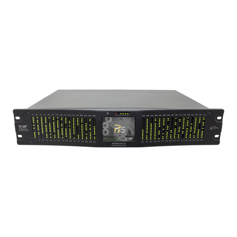
TDT Medusa4Z User manual

ABR User Guide
Medusa4Z Amplier
Updated 2021-03-24

© 2016-2021 Tucker-Davis Technologies, Inc. (TDT). All rights reserved.
Tucker-Davis Technologies
11930 Research Circle
Alachua, FL 32615 USA
Phone: +1.386.462.9622
Fax: +1.386.462.5365
Notices
The information contained in this document is provided "as is," and is subject to being changed,
without notice. TDT shall not be liable for errors or damages in connection with the furnishing, use, or
performance of this document or of any information contained herein.
The latest versions of TDT documents are always online at https://www.tdt.com/docs/
ABR User Guide | 2

Table of Contents
ABR Testing with the RZ6 and Medusa4Z
5ABRs - from Set-up to Data Collection
The Subject
9Expected Hearing Range
10Age-Related Effects on Hearing
10Anesthesia Considerations
Your Test Area
11Grounding
11Enclosure Considerations
12Speaker Placement
12Vibrations
12Heating Pads
The Test Equipment
14Needle Electrodes
15Medusa4Z BioAmp
16Speakers
17RZ6 Signal Processor
BioSigRZ Software
21Click ABRs
22Tone ABRs
22Out-of-the-Box Experiments
23The Stimulus Settings
25The Acquisition Settings
Running the Experiment
27Electrode Placement
28Check Impedance
28Check Sedation
29Begin Experiment
30Modifying the Stimulus Schedule
30Multi-Purpose Plot
31Termination
Data and Export
33History Plot
34The Worksheet
34Export Data
Table of Contents | 3

Troubleshooting
36Determining the Noise Floor
37Diagnosing Noise Issues
38Troubleshooting On-The-Fly
39Getting Help
Calibration
40How Often to Calibrate
41Hardware Setup
41Closed Field
43Tone Calibration
43Click Calibration
46Testing Speakers and Microphones
Sound Chamber Fundamentals
50Reections and Interference
52Ways to Reduce Reections and Interference
Conguring MF1 for Closed Field
Modifying the Stimulus
59Modifying Variables
61Customizing the Stimulus
64Suggested Stimulus File Changes
65Wrapping up
Noise Exposure
66Key elements of noise exposure:
66Hardware Requirements:
67Setting Up Signal Generation in RPvdsEx
74Preparing a Suitable Enclosure
76Working with Multiple Subjects
Upgrading from RA4PA to Medusa4Z
78Hardware Setup
80Software Updates
80Hardware Updates
80Software Conguration Changes
81Wrapping up
Table of Contents | 4

ABR Testing with the RZ6 and Medusa4Z
ABRs - from Set-up to Data Collection
This guide is primarily intended for researchers who are new to collecting ABRs using a TDT
RZ6 system with Medusa4Z preamplier and BioSigRZ software. It brings together targeted
information from our software and hardware manuals and goes beyond product specic
details to answer common questions, including subject or test area considerations that might
affect your testing. The information provided is based on our knowledge of the TDT system
and years of experience helping our users. It is not intended to favor or dictate any particular
experimental protocols, methods, or research goals.
We leave the science up to you, but we are here to support you on your way to successful
experiment completion.
Organization of the Guide
This guide begins with a general overview of ABRs; what they are, how they are used, and what
type of response signal to expect. It discusses the various aspects of your experiment such as
test subjects, your test area, and the hardware and software you will use. It includes detailed
information about important tasks, including:
Running the ABR
Viewing and exporting test results
System calibration
Diagnosing noise issues
Several appendices provide supplemental information included to provide supplemental
information on:
Sound chamber setup
Closed eld operation
If using the RA4PA/RA4LI instead of the Medusa4Z, see
ABR Guide for RZ6 and RA4PA
.
Important
•
•
•
•
•
•
ABR Testing with the RZ6 and Medusa4Z | 5

Modifying the stimulus parameters
Conducting noise exposure experiments
ABR Overview
An ABR is a synchronous neural response to an auditory stimulus. ABR testing can be used to
estimate hearing sensitivity. The ABR is an early potential, occurring shortly after stimulus
onset, and is typically in the 1 - 2.5 microVolt range, so small that it can be masked by the
background activity of the brain. Because ABRs are repeatable in response to stimuli, signal
averaging can be used to clearly identify the response in recorded data.
A short click or tone stimulus is presented rapidly and response data is collected and averaged
to reduce background noise and isolate the signal. Typically, four times as many sweeps
averaged together will reduce the background noise by half.
When viewing ABR responses, you can expect to see an averaged waveform trace, consisting
of multiple features with at least two distinct peaks. The response shape should be consistent
but can change in response to changes in the auditory stimulus, such as intensity or polarity.
After averaging, the response should clearly stand out above the noise oor of the system.
Identifying the Threshold
As the level of the stimulus is decreased, the amplitude of the response gets smaller and the
latency gets longer, this makes the biologic features less distinct. The lowest intensity at which
the response is present is generally considered the hearing threshold for the given set of
variables. The determination of response or no response is left up to the researcher. Because
noise and artifacts can mask the very small threshold response, quiet recordings are critical to
accurate threshold testing.
•
•
ABR Testing with the RZ6 and Medusa4Z | 6

Averaged ABR Response Waveforms
ABR Recordings
ABRs are a useful and reliable tool for hearing screening. To get the clearest possible
responses, you will need to record using high delity equipment in a quiet environment. The
subject must be anesthetized and kept warm to prevent movement or stress from affecting the
response. Recordings should be performed in a shielded enclosure that has been set-up to
minimize noise interferences.
The TDT system for ABR recording is designed to minimize noise at every step, beginning with
an optically isolated, battery powered Medusa4Z preamplier. This device digitizes the biologic
responses right in the enclosure. The processor (RZ6) brings together stimulus production and
data collection on a single device and a single clock for precise timing. The system software
for experiment control and data visualization is PC based and is more exible than clinical
systems while still easy to use.
The diagram below shows a typical ABR system. Each part of the system will be discussed in
more detail as you read through this guide.
ABR Testing with the RZ6 and Medusa4Z | 7

Typical System Using TDT's RZ6 Processor and Medusa Preamplier
What you'll need:
Windows computer (WS4 shown)
Optibit interface (installed in computer)
TDT Drivers (software installed on computer)
BioSigRZ (software installed on computer)
Computer monitor
Multi I/O Processor with optic port (RZ6-A-P1)
Medusa4Z 4-channel amplier.
Speaker (MF1)
Calibration microphone (PCB-378C01) (not shown)
Needle electrode kit (ELE-N)
Cable kit (BNC-ABR)
Sound attenuating subject enclosure with Faraday cage
Heating pad
Subject
Anesthesia (not shown)
1.
2.
3.
4.
5.
6.
7.
8.
9.
10.
11.
12.
13.
14.
15.
ABR Testing with the RZ6 and Medusa4Z | 8

The Subject
Planning or setting up your ABR experiment must begin with an understanding of the subject's
normal hearing range and factors that might have an effect on its response or recording. ABRs
have been measured for many species. In this guide, we'll focus on the three most common
species used in ABR experiments and screening protocols: mice, rats, and guinea pigs.
Expected Hearing Range
ABR tests are typically focused on the range in which the species is commonly known to hear
well.
Subject Standard Testing Range Typical Threshold Range
Mice 4 kHz to 32/48 kHz > 25 - 30 dB at 16 kHz
Rats > 4 kHz to 24/32 kHz > 30 dB at 16 kHz
Guinea Pigs > 1 kHz to 18 kHz > 30 dB at 8 kHz
The
hearing
range
of
laboratory
subjects
may
vary
across
different
strains
or
colonies
and
can
be
affected
by
age,
the environment, and anesthesia.
Note
The Subject | 9

Age-Related Effects on Hearing
Many lab subjects experience hearing loss due to age. The rate of loss varies across species
and strains. This effect has been observed as early as 12 weeks in mice.
Anesthesia Considerations
Two types of anesthesia protocols are typically used for ABR testing. Each has benets and
limitations. Check your IRB approved guidelines for dosages and protocol.
Xylazine(XYL) + Ketamine to start, Ketamine to Boost
This aesthetic protocol uses an injectable combination of muscle relaxer and sedative.
Typically, the subject is unconscious in a few minutes, begins to wake ~45 minutes and is
completely awake at ~90 minutes after initial sedation. If a subject wakes early or a test runs
longer than ~45 minutes, a booster of ketamine can be used to keep the subject anesthetized.
Be sure to follow your approved IRB protocol.
Isourane (ISO)
This aesthetic protocol uses a fast-acting inhalant with a short duration. The subject is
typically fully sedated within 4-5 minutes and wakes very quickly when the gas is removed.
The Subject | 10

Your Test Area
The small size (1 - 2.5 microVolt @ 90dB stimulation) of typical ABR response signals makes it
especially important to minimize electrical noise in the test area and to ensure all conditions
are carefully controlled during testing. Be sure to consider the elements detailed below in
setting up your testing area.
Grounding
Use a designated and grounded electrical outlet.
Enclosure Considerations
Many labs are full of cables, metal structures and other items that generate noise as well as
electrical wires that serve as antennas for electrical noise. We recommend using a sound
attenuating chamber with a built in Faraday cage for ABR testing. It is equally important to use
good practices when using the selected enclosure. A mains power cord that extends from
outside the enclosure to inside the enclosure undermines its integrity.
To maintain the integrity of the enclosure:
Keep AC electrically powered devices (wall/mains powered) outside.
Ensure the preamplier is completely inside your enclosure.
Ensure the preamp charger is unplugged and outside the enclosure.
Ensure electrode wires are completely inside the enclosure.
Verify the enclosure door shuts securely.
•
•
•
•
•
Your Test Area | 11

Speaker Placement
Most enclosures have some amount of acoustical reection or interference during open eld
stimulus presentation. The effects will vary depending on the size of the enclosure, the angle at
which the speaker is positioned, and the materials used or added for sound dampening. To
minimize the effects of distortion or interference, position the stimulus speaker on the same
plane as the subject's ear and set at an angle from the sides of the enclosure. See Sound
Chamber Fundamentals for more information on speaker placement.
Vibrations
Vibration from nearby large equipment is another common source of noise. If this is a problem
in your lab, the cage and subject can be positioned on an air table or anti-vibration table.
Heating Pads
When the subject is sedated for testing, it cannot generate enough body heat to maintain core
temperature. When the subject loses body heat, its hearing system is not as responsive which
can articially raise hearing thresholds. A heating pad is typically used to maintain the
subject's temperature. Heating pads that require AC power inside the chamber are not suitable
for ABR recordings.
Below are two alternative types of heating pads used for this purpose:
An Isothermal Pad contains a phase change material that changes state near the subject's
body temperature. It can be heated in a microwave and can typically hold a constant
temperature for an hour or more.
Example: http://www.braintreesci.com/images/DP.pdf
A Warm Water Recirculator moves warm uid through a small subject heating pad to keep the
subject's body temperatures stable. Because this method uses an external heating element
and pump to transfer water to the pad via non-ferrous tubes, the recordings will not be
affected.
Examples: http://www.braintreesci.com/prodinfo.asp?number=HTP-1500 and http://
www.braintreesci.com/prodinfo.asp?number=TP-700
Your Test Area | 12

It
is
critical
that
you
place
the
heat
pump
and
all
associated
electrical
connections
outside
the
Faraday
cage
when using this type of pad.
Important
Your Test Area | 13

The Test Equipment
The care used in setting up your test area must also be taken when selecting and setting up
your test equipment. TDT's ABR system is part of a modular experiment platform. Each module
in the system is designed for exceptional signal delity, precise timing, low noise, and ease of
use.
The sub-sections below discuss the role each part of the system plays in running an ABR
experiment and provides information on making the necessary connections.
Needle Electrodes
In a research environment with non-human subjects, ABRs are typically recorded using sub-
dermal needle electrodes. There are a wide variety of suitable electrodes available. When
working with a TDT System, you will need electrodes with 1.5 mm female safety connectors
(also known as Touch-Proof connectors) to be used with the Medusa4Z. TDT recommends
disposable, 12 mm long, 27 gauge needle electrodes with 18" color coded lead wires. In
general, selecting the shortest available lead wires helps keep the noise oor as low as
possible. Some test protocols using small subjects, such as mice, may nd that 29 gauge
electrodes are more workable. Keep in mind that smaller gauge electrodes are lighter, but are
also less robust and more likely to dull quickly.
The Test Equipment | 14

Medusa4Z BioAmp
Biological signals from the subject are input to the Medusa4Z for amplication and
digitization. The Medusa4Z transfers digitized data to the RZ6 processor via a ber optic cable.
The ber optic connection electrically isolates the Medusa4Z from the RZ6 and ensures that
no additional noise is introduced to the biologic signal. This design is intended to be used with
the preamplier running on battery power alone, placed inside the Faraday cage with only the
ber optic cable connecting it to the RZ6.
Max Input: ± 10 milliVolts max input.
Gain: The Medusa4Z amplies the signal by 100x before digitizing and transferring it to the
RZ6. The RZ6 automatically accounts for this 100x gain when receiving the data, yielding a net
unity gain.
Power: The Medusa4Z is powered by a Lithium-ion battery. It can be charged in 4-6 hours and
will power the amplier for up to 30+ hours when using a single active channel.
By default the Medusa4Z will boot up as shown above. A few changes must be made to the
default settings to use for ABRs.
The
supplied
battery
charger
must
NOT
be
connected
or
inside
the
enclosure
when
running
experiments.
To
protect the battery, do not leave the Medusa4Z on the charger for an extended period of time (1+ week).
Important
The Test Equipment | 15

For more information on the Medusa4Z and full system specs, see the System 3 Manual.
Speakers
TDT's MF1 Multi-Field Magnetic Speaker is suitable for testing the hearing range of mice, rats,
and guinea pigs. It can be congured for either free- or closed- eld use. See Conguring the
MF1 for Closed Field Operation. It has a built-in 8-32 threaded hole for use with standard
laboratory mounting hardware. Aluminum mount/base ttings are included for easier
positioning.
Setting Notes
Active Channels Single. We are typically recording from one channel only and this conserves energy.
Sample Freq 12KHz (6KHz). Sampling rate of the Medusa4Z. 12KHz yields improved signal delity in the ABR
signal frequency range.
Impedance Frq 1KHz. This is the frequency used for the built-in electrode impedance tester. 1KHz is the closest
frequency to the ABR signal frequency range. See Check Impedance for tips and troubleshooting
electrode impedance.
Highpass Filt 3Hz. Built-in highpass lter conditions the signal before it is digitized.
Auto Shutdown Optionally set the Medusa4Z to shut off automatically when not in use. This allow users to run
their normal protocols, and then power off if the user no longer operates the PreAmp. This will
save future users from a dead battery.
Use
the
POWER
button
on
the
top
of
the
Medusa4Z
to
turn
it
on
and
off.
There
is
an
ON/OFF
(RESET)
switch
on
the
side
which
completely
disconnects
the
battery
and
loses
all
user
settings.
You
should
only
use
the
ON/OFF
(RESET) switch if storing the Medusa4Z for an extended period of time.
Caution
The Test Equipment | 16

For Open Field experiments, place the speaker 10 cm from the subject. Be sure to position it to
the side of the subject, in line with the ear, NOT in front of the subject.
For more information on the MF1 speakers and full system specs, see the System 3 Manual.
Closed Field Setup
Each MF1 comes with a tapered tip for Closed Field experiments. The tip mates with the
provided ⅛" outside diameter (O.D.) PVC tubing (10 cm included). The MF1 comes with an
inline lter (pictured at left) that connects between the RCA cable and speaker input. This lter
should always be in place when using the MF1 speakers in closed-eld mode. In closed-eld
mode, the MF1 has undesirably high low frequency output. This lter reduces the speaker
output at low frequencies so that the output range can be equalized. When using the tube tip,
use the MF1's inline lter and the shortest tube possible. You can cut the 10 cm tube to the
desired length. A 3 - 5 cm tube length is typical. The tube should slide snugly into the tube tip.
You can push rmly without fear of damaging the tube. If you have trouble inserting the tube, a
small amount of silicon spray can be used. It may be easiest to spray silicone lightly on a cloth
rst then put the tip of the tube on the cloth to apply it.
RZ6 Signal Processor
The RZ6-A-P1 Multi I/O Processor provides the processing power for averaging signal inputs
and the digital-to-analog converters and ampliers for producing the stimuli. It also provides
the precise timing essential to evoked response experiments.
Other
lubricants
(WD-40,
grease
sprays,
or
similar)
should
not
be
used
as
they
can
damage
the
O-rings
surrounding the tube tip, or the tubes themselves.
Warning
The Test Equipment | 17

The power input and optical connection to the PC are located on the back. The input/output
support (such as speaker drivers) and attenuation that is incorporated into the device are all
accessed on the front panel.
Stimulus Output The RZ6's can generate a stimulus in the frequency range of DC - 88 kHz and
is well suited for standard ABR testing.
A built-in stereo power amplier drives the stimulus signals through TDT's MF1 multi-function
speaker via the BNC labeled Out-A.
Use the RCA cable and BNC to RCA adapter (included with the MF1 kit) to connect OUT-A to
the RCA connector on the speaker.
Attenuation Typically, stimulus attenuation is handled via software. The Atten knob on the front
panel provides optional manual attenuation applied to the signal before it is output. This can
When
using
the
MF1,
the
ON/OFF
switch
next
to
the
outputs
marked
Electrostatic
must
be
in
the
OFF
position
to
reduce noise.
Important
The Test Equipment | 18

be useful if the sound level is found to be systematically too high across all frequencies during
speaker calibration.
Fiber Optic Input Biological signals are digitized on a Medusa4Z preamplier and transferred
to the RZ6 via the ber optic port marked 'Optical In'.
Use the provided ber optic pair (white connectors) to connect the To Base port on the
preamplier to the Optical In port on the RZ6.
The duplex ber optic cable has identical one-piece connectors at each end. There is a V-
shaped groove on one side of the connector and a raised rectangle on the other. As shown in
the image above, plug the connector into the RZ6 port with the raised rectangle side up. Plug
the connector into the preamplier with the V-shaped groove up.
The green LED next to the Optical In port on the RZ6 will illuminate when the preamplier is
connected and both devices are powered on. This indicates that the Medusa4Z is properly
time-locked with the RZ6.
Mic Inputs The BNC input connector is used during system calibration. See Calibration.
The Test Equipment | 19

For more information on the RZ6 and full system specs, see the System 3 Manual.
PC and Interface
The RZ6 must be directly connected to a PC, which provides the user interface for the system.
The PO5 or PO5e optical interface card is installed in the PC and connected to the RZ6 across
ber optic cables. This adds another layer of noise reduction, separating the processor from
the noisy PC environment.
The PC handles:
Conguring the hardware and software.
Communicating with the TDT hardware and transferring data across a ber optic
interface.
Displaying and working with data during and after acquisition.
If you use TDT's WS4 computer, the optical interface and BioSigRZ software are pre-installed.
If you use your own PC, you'll need to install the interface card and BioSigRZ software yourself.
Step-by-step instructions for installing software and drivers and setting up the processor are
available in System 3 Installation Guide that came with your system. The installation guide also
includes information for connecting the WS4 or your PC to the RZ6 Processor, including
running a transfer test to ensure communication between them is working correctly.
•
•
•
A UZ3 (USB 3.0) interface is also available if you wish to use a laptop.
Note
The Test Equipment | 20
Other manuals for Medusa4Z
2
Table of contents
Other TDT Amplifier manuals
Popular Amplifier manuals by other brands
Meridian
Meridian Meridian 565 User's manual supplement
AUSTRALIAN MONITOR
AUSTRALIAN MONITOR PICOBLU Installation and operation manual
Pioneer
Pioneer SP-X707 operating instructions
Pioneer
Pioneer GM-D1004 owner's manual
VIETA
VIETA VC-AM400PW user manual

Chandler Limited
Chandler Limited GERM 500 MKII Controls and features
