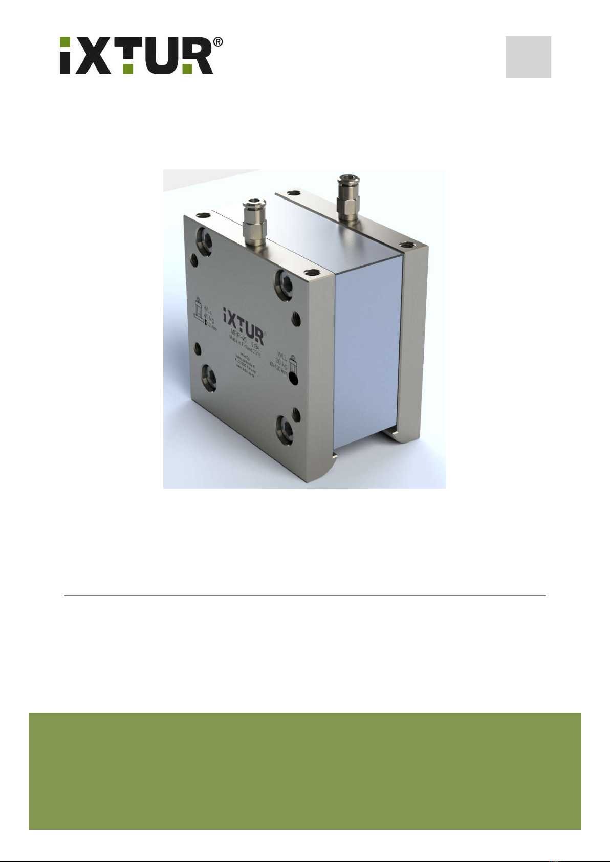
Ixtur Ltd / MRP-45
Technical Specifications
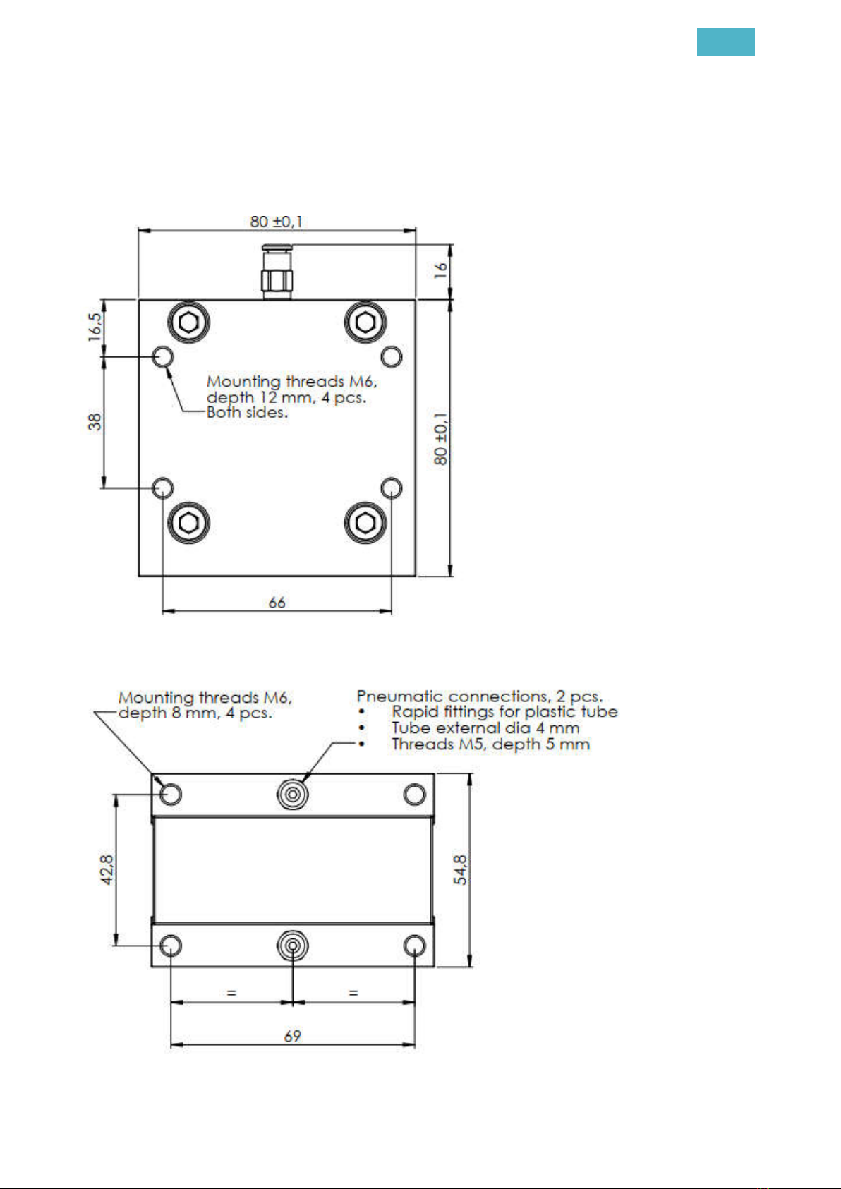
Dimensions:
- Length: 80.0 mm
- Width 54.8 mm
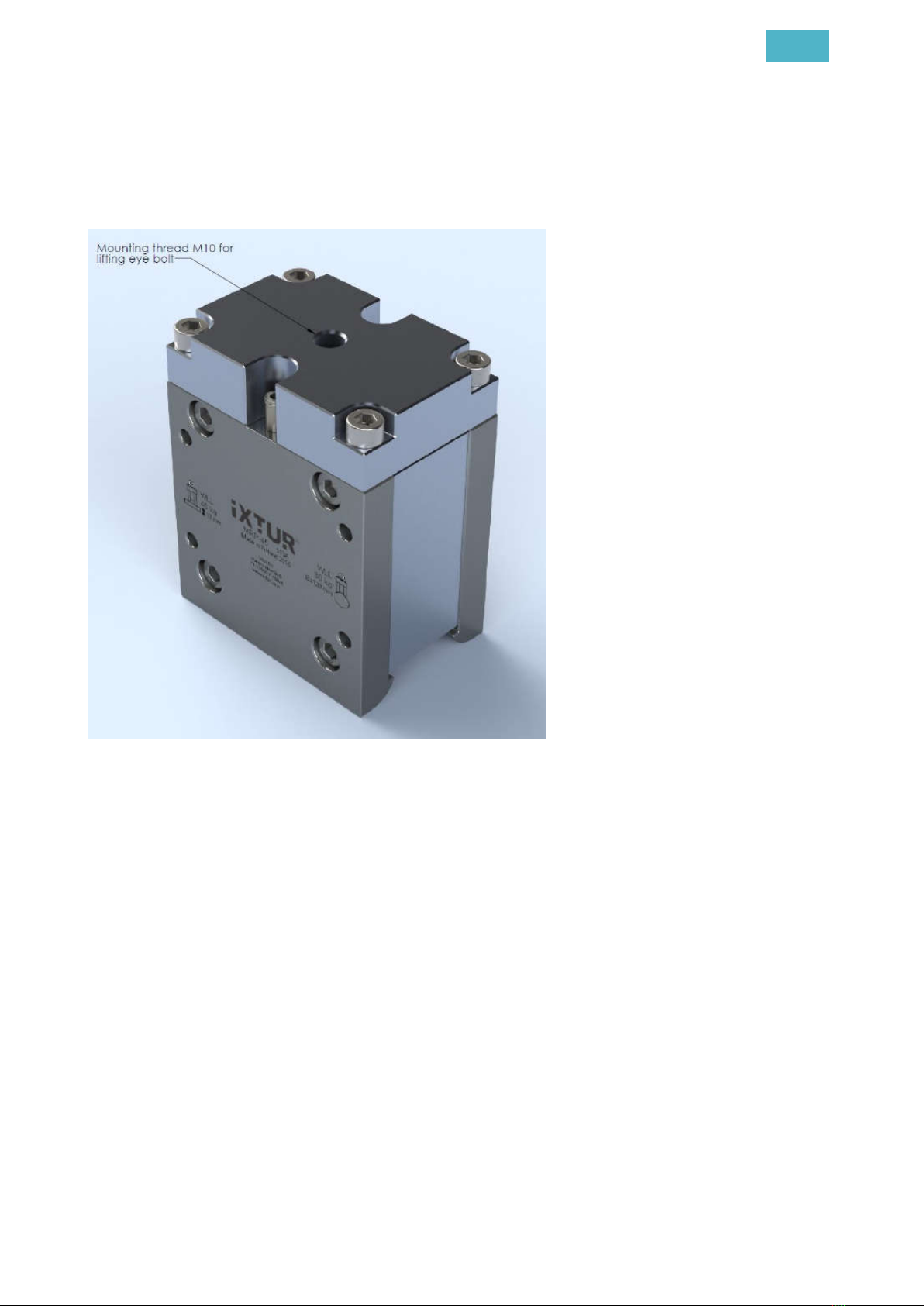
- Height: 80.0 mm (height with lifting adapter 100.0 mm)
- Weight: 1790 g (weight with lifting adapter 2000 g)
Capacity:
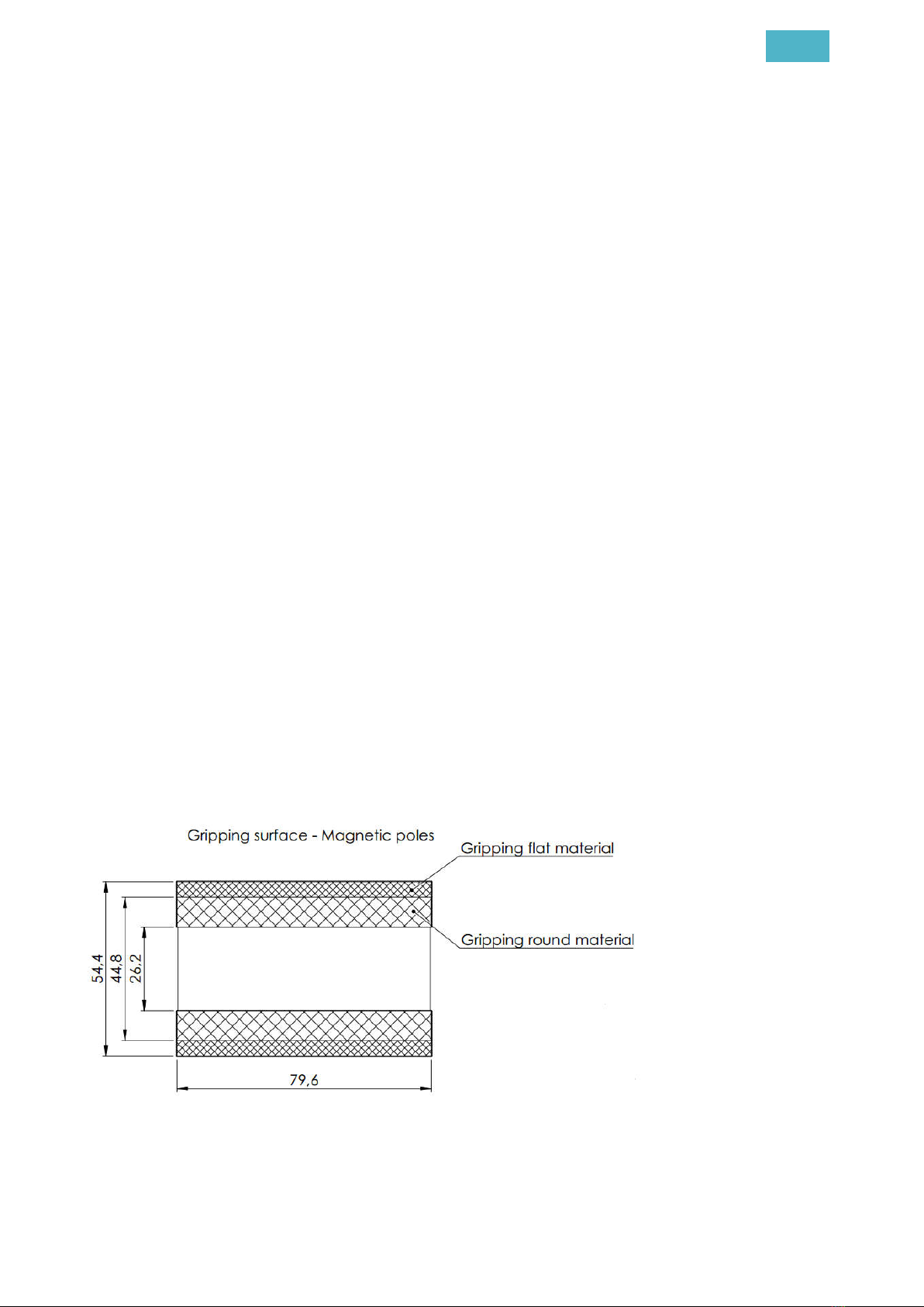
- Rated holding force: 1324 N (S355 S ≥ 12 mm plate)
- Rated holding force: 883 N (S355 cylinder ø ≥ 120 mm)
- Rated lifting capacity for plate with safety factor 3: 45 kg (S355 S ≥ 12 mm)
- Rated lifting capacity for solid round object with safety factor 3: 30 kg (ø ≥ 120 mm)
- Residual holding force flat: maximum 1200 g
- Residual holding force for other shapes:
MRP-45’s magnetic structure (similar to standard lever magnets) makes residual grip-
ping capacity sensitive to material and geometry of the lifted part. In extreme case, a
part up to 4 kg may stay connected to the magnet. This may happen just after the mag-
net has been turned OFF. When this behavior is critical to the application, the actual
parts need to be pretested with the MRP-45 magnet.
Environmental conditions:
- Operating temperature: 0 °C … +50 °C
- Storage temperature: -20 °C … +50 °C
- Humidity 0 % … 90 %
- IP67 (The device is protected from dust and temporary immersion up to 1 m)
Requirements for compressed air:
- Recommended pressure: 6.0 bar
- Functional range: 5.0 … 8.0 bar
- Water separation
- Particle filter ≤ 5µm
Information related to medical implants
- Safety distance for a person with active implanted device is 50 cm of air or other non-
magnetic material. The distance is measured from the magnet or magnetic material
attached to it.
o Maximum static magnetic field of MRP-45 is 200 mT on the gripping surface.
o Interference with active implanted devices, e.g. cardiac pacemakers – Action level for expo-
sure to static magnetic fields is 0,5 mT [Directive 2013/35/EC].