TE Pro Crimper III 58517-1 User manual
©2012 Tyco Electronics Corporation, a TE Connectivity Ltd. Company
All Rights Reserved
*Trademark
TE Connectivity, TE connectivity (logo), and TE (logo) are trademarks. Other logos, product and/or Company names may be trademarks of their respective owners.
1of 5
Instruction Sheet
TOOLING ASSISTANCE CENTER
1-800-722-1111
PRODUCT INFORMATION
1-800-522-6752
This controlled document is subject to change.
For latest revision and Regional Customer Service,
visit our website at www.te.com LOC B
408-4064
PRO-CRIMPER* III Hand
Crimping Tool Assembly And
Die Set 58517-[ ] 10 MAY 12 Rev F
PROPER USE GUIDELINES
Cumulative Trauma Disorders can result from the prolonged use of manually powered hand tools. Hand tools are intended for occasional use
and low volume applications. A wide selection of powered application equipment for extended-use, production operations is available.
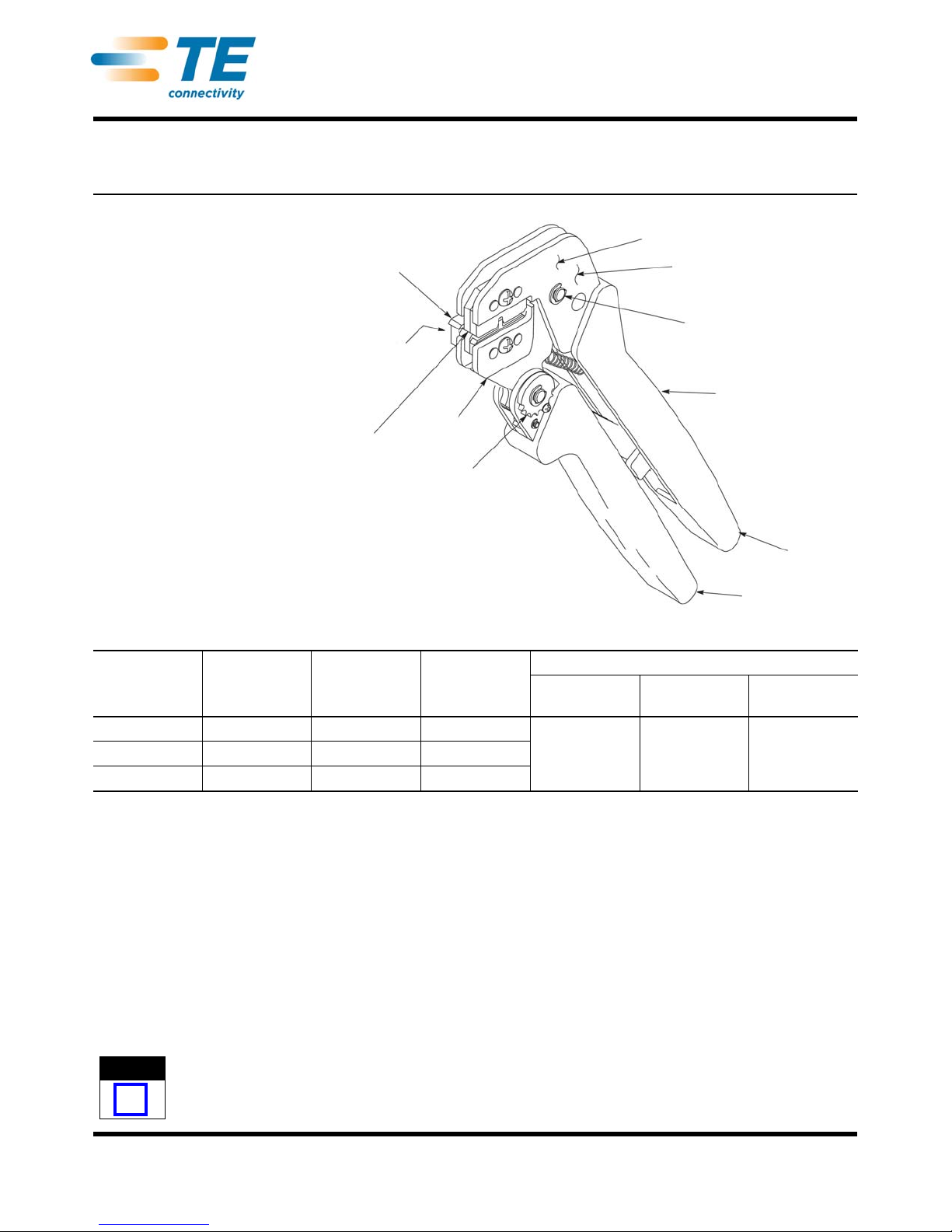
Figure 1
1. INTRODUCTION
PRO-CRIMPER III Hand Crimping Tool Assembly
58517-1 consists of Die Assembly 58517-2 and
PRO-CRIMPER III Hand Tool Frame 354940-1. See
Figure 1.
The die assembly consists of crimping dies and a
locator assembly.
Read these instructions thoroughly before crimping
any contacts.
Dimensions on this sheet are in millimeters [with
inch equivalents provided in brackets]. Figures and
illustrations are for identification only and are not
drawn to scale.
Reasons for reissue are provided in Section 11,
REVISION SUMMARY.
2. DESCRIPTION (See Figure 1 and Figure 2.)
The tool features a tool frame with a stationary jaw
and handle, a moving jaw, a moving handle, and an
adjustable ratchet that ensures full contact crimping.
The tool frame holds a die assembly with one crimping
section.
The die assembly features a wire anvil, an insulation
anvil, a wire crimper, and an insulation crimper.
Attached to the outside of the frame is a locator, which
holds and helps to position the contact.
PRO-CRIMPER
III HAND TOOL DIE ASSEMBLY
PART NUMBER
LOCATOR
PART
NUMBER‡
CONTACT
FAMILY
WIRE
SIZE
(AWG) INSUL DIA
(mm [in.]) STRIP LENGTH
(mm [in.])
58517-1 58517-2 189590-1 CST 100 26-22 0.89-1.65
[.035-.065] 2.54-2.92
[.100-.125]
58517-3 58517-4 1424907-1 CST 100 II
None 58517-5 • 1901843-1 CST 100 II
• Bench Machine/Battery and
SDE-SA Hand Tool Only ‡ Supplied with the die assembly. Also available
separately. ‡‡ Contact the PRODUCT INFORMATION CENTER for specific contact part
numbers.
NOTE
i
The PRO-CRIMPER III Hand Crimping Tool is a “Commercial” grade tool
and is designed primarily for field installation, repair, maintenance work, or
prototyping in industrial, commercial, or institutional applications. Product
crimpedwiththistool willmeetthecrimpheightrequirementforhandtoolsin
the appropriate Application Specification (114-series), but may not comply
with other feature parameters of the specification. TE Connectivity offers a
variety of tools to satisfy your performance requirements. For additional
information, contact the Tooling Assistance Center at 1-800-722-1111.
Locator
(Supplied with
Die Assembly)
Front of Tool
(Locator Side)
Die Assembly Moving Jaw
Ratchet Adjustment Wheel
Stationary Jaw
Back of Tool
(Wire Side)
Pivot Pin
PRO-CRIMPER III
Hand Crimping
Tool Frame
354940-1
(Instruction
Sheet 408-9930)
Moving
Jaw
Handle
ORIGINAL INSTRUCTIONS
408-4064
2of 5
Rev F
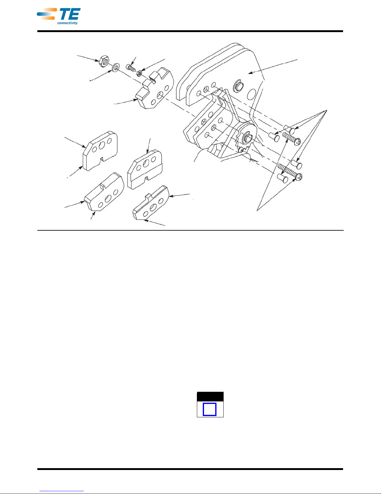
Figure 2
Die retaining pins and die retaining screws are used to
position and secure the dies in the tool frame. A
washer and nut is used on the lower die retaining
screw to hold the locator in place.
3. INSTALLATION AND REMOVAL OF DIE SET AND
LOCATOR ASSEMBLY (Figure 2)
1. Open the tool handles and remove the two die
retaining screws from the tool jaws.
2. Place the wire anvil and insulation anvil in the
moving jaw so that their chamfered sides and
their marked surfaces face outward, when
mounted in the moving jaw of the tool frame.
3. Insert the two die retaining pins.
4. Insert the long die retaining screw through the
jaw and through both anvil dies, and tighten the
screw just enough to hold the dies in place. Do
not tighten the screw completely at this time.
5. Place the wire crimper and insulation crimper
in the stationary jaw so that their chamfered sides
and their marked surfaces face outward, when
mounted in the stationary jaw of the tool frame.
6. Insert the two die retaining pins.
7. Insert the short die retaining screw through the
jaw and through both crimper dies, and tighten
the screw just enough to hold the dies in place.
Do not tighten the screw completely at this time.
8. Carefully close the tool handles, making sure
that the anvils and crimpers align properly.
Continue closing the tool handles until the ratchet
in the tool frame has engaged sufficiently to hold
the anvils and crimpers in place, then tighten both
die retaining screws.
9. Place the locator over the end of the long
screw, and position the locator against the side of
the tool jaw.
10. Place the washer and nut onto the end of the
long screw. Align the locator slot with the
crimping section and carefully tighten the nut.
11. To disassemble, close the tool handles until
the ratchet releases, remove the nut, the washer,
the locator, the two die retaining screws, and the
four die retaining pins, and slide the anvils and
crimpers out of the tool jaws.
4. CRIMPING PROCEDURE
This tool is provided with a crimp adjustment
feature. Initially, the crimp height should be verified
as specified in Figure 4. Refer to Section 6, Crimp
Height Inspection, and Section 7, Crimp Height
Adjustment, to verify crimp height before using the
tool to crimp desired contacts and wire sizes.
Nut
Washer
Locator
Chamfer
Wire
Crimper
Offset
Wire Anvil Chamfer
Insulation
Anvil
Insulation
Crimper
Nut
Die Retaining Screws
Die
Retaining
Pins
Tool Frame
(or Bench
Machine, or
Ratched Hand
Tool)
Adjustment Screw
(See Figure 3)
NOTE
i
408-4064
3of 5
Rev F
Refer to the table in Figure 1 and select wire of the
specified size and insulation diameter. Strip the wire to
the length indicated in Figure 1, taking care not to nick
or cut wire strands. Select an applicable contact and
identify the appropriate die assembly according to the
wire size markings on the die. Refer to Figure 3 and
proceed as follows:
1. Hold the tool so that the back (wire side) is
facing you. Squeeze tool handles together and
allow them to open fully.
2. Holding the contact by the insulation barrel,
insert the contact—mating end first—into the
locator slot. Position the contact so that the open
“U” of the wire and insulation barrels face the top
of the tool. Make sure the contact butts against
the adjustment screw. Check that the contact is
centered with the die assembly wire and
insulation anvils. If adjustment is required, refer to
Section 5, CONTACT SUPPORT ADJUSTMENT.
Make sure that both sides of the insulation barrel
are started evenly into the crimping section. Do not
attempt to crimp an improperly positioned contact.
3. Hold the contact in position and squeeze the
tool handles together until ratchet engages
sufficiently to hold the contact in position. Do
NOT deform insulation barrel or wire barrel.
The ratchet has detents that create audible clicks
as the tool handles are closed.
4. Insert stripped wire into contact insulation and
wire barrels until it is butted against the wire stop
on the contact, as shown in Figure 3.
5. Holding the wire in place, squeeze tool handles
together until ratchet releases. Allow tool handles
to open and remove crimped contact.
6. Check the contact's crimp height as described
in Section 6, Crimp Height Inspection. If
necessary, adjust the crimp height as described
in Section 7, CRIMP HEIGHT ADJUSTMENT.
5. CONTACT SUPPORT ADJUSTMENT (Figure 3)
1. .Make a sample crimp according to Section 4,
CRIMPING PROCEDURE. If the crimp is out of
alignment, adjustment is required.
2. To move the contact from side-to-side, loosen
the nut that holds the locator to the frame and
slide the locator until the contact is properly
positioned. Hold the locator in place and tighten
the nut.
3. To move the contact in or out, loosen the nut
on the adjustment screw and turn the screw until
the contact is properly positioned. Hold the screw
in place and tighten the nut.
4. If the crimp is still out of alignment, repeat the
adjustment procedure.CRIMP HEIGHT
INSPECTION.
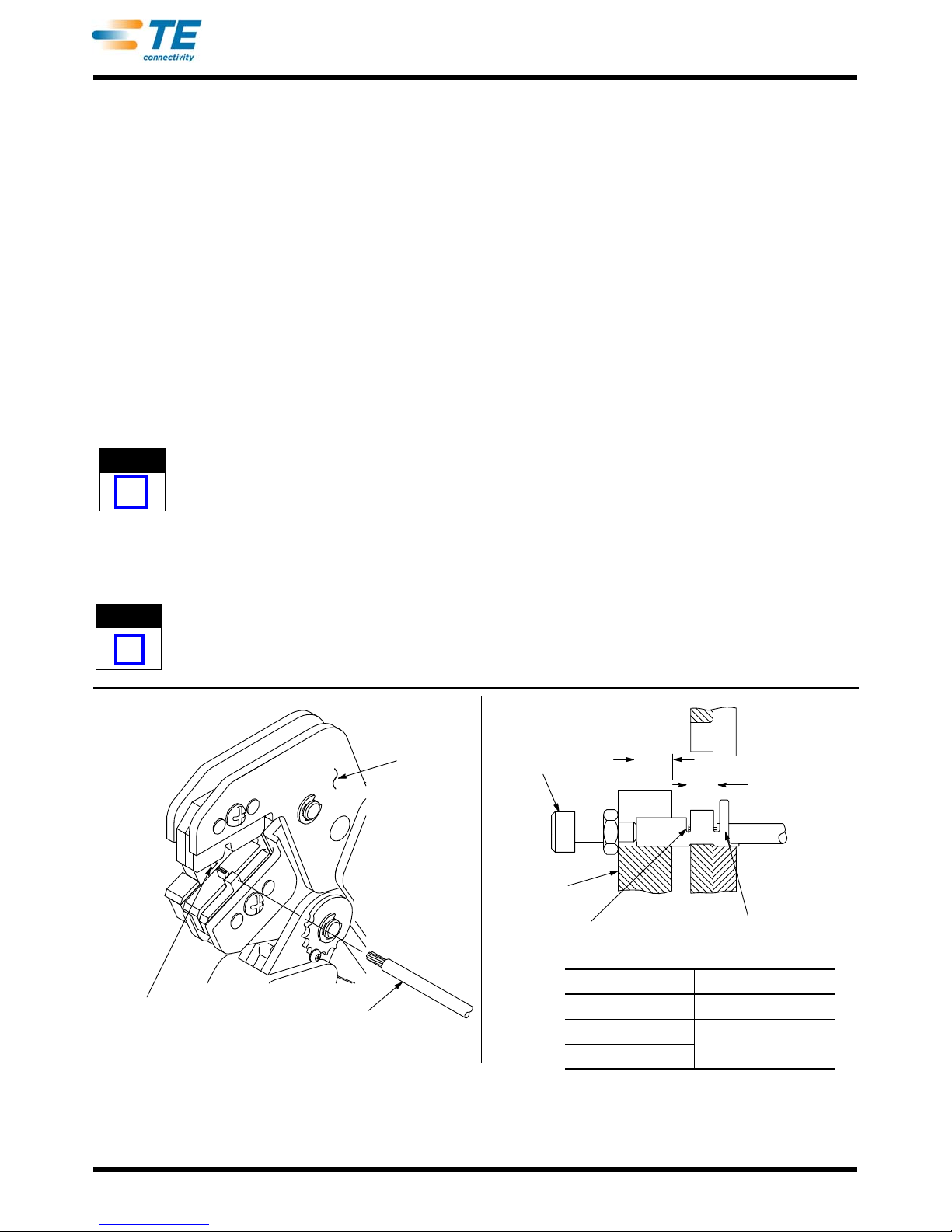
Figure 3
NOTE
i
NOTE
i
TOOL DIMENSION A
58517-1, 58517-2, 2.641 [.104]
58517-3, 58517-4 4.191 [.165]
58517-5
Locator Slot Wire
Back of Tool
(Wire Side) Adjustment
Screw
Locator
Wire Inserted to
Contact Wire Stop Wire Inserted
in Contact
Strip
Length
“A”
408-4064
4of 5
Rev F
.
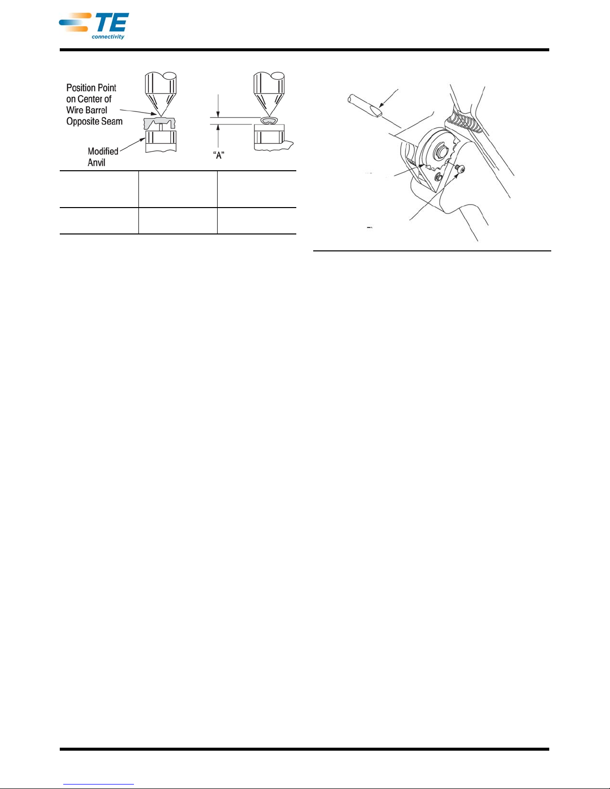
Figure 4
6. CRIMP HEIGHT INSPECTION
Crimp height inspection is performed through the
use of a micrometer with a modified anvil,
commonly referred to as a crimp height comparator.
Tyco Electronics does not market crimp height
comparators. Refer to Instruction Sheet 408-7224
for detailed information on obtaining and using a
crimp height comparator.
Proceed as follows:
1. Refer to Figure 4 and select a wire (maximum
size) for the crimp section.
2. Refer to Section 4, CRIMPING PROCEDURE,
and crimp the contact(s) accordingly.
3. Using a crimp height comparator, measure the
wire barrel crimp height as shown in Figure 4. If
the crimp height conforms to that shown in the
table, the tool is considered dimensionally
correct. If not, the tool must be adjusted. Refer to
Section 7, CRIMP HEIGHT ADJUSTME
7. .CRIMP HEIGHT ADJUSTMENT (Figure 5)
1. Remove the lockscrew from the ratchet
adjustment wheel.
2. With a screwdriver, adjust the ratchet wheel
from the locator side of the tool.
3. Observe the ratchet adjustment wheel. If a
tighter crimp is required, rotate the adjustment
wheel COUNTERCLOCKWISE to a higher-
numbered setting. If a looser crimp is required,
rotate the adjustment wheel CLOCKWISE to a
lower-numbered setting.
4. Replace the lockscrew.
5. Make a sample crimp and measure the crimp
height. If the dimension is acceptable, replace
and secure the lockscrew. If the dimension is
unacceptable, continue to adjust the ratchet, and
again measure a sample crimp.
Figure 5
8. MAINTENANCE
Ensure that the tool and dies are clean by wiping them
with a clean, soft cloth. Remove any debris with a
clean, soft brush. Do not use objects that could
damage the tool. When not in use, keep handles
closed to prevent objects from becoming lodged in the
crimping dies, and store in a clean, dry area.
9. VISUAL INSPECTION
The crimping dies should be inspected on a regular
basis to ensure that they have not become worn or
damaged. Inspect the crimp section for flattened,
chipped, worn, or broken areas. If damage or
abnormal wear is evident, the tool must be replaced.
See Section 10, REPLACEMENT.
10. REPLACEMENT
Customer-replaceable parts are shown in Figure 1.
Available separately, PRO-CRIMPER III Hand Tool
Repair Kit 679221-1 includes a replacement nut and a
variety of pins, rings, screws, and springs. If the dies
are damaged or worn excessively, they must be
replaced. Order the repair kit and replaceable parts
through your TE representative, or call 1-800-526-
5142, or send a facsimile of your purchase order to 1-
717-986-7605, or write to:
CUSTOMER SERVICE (038-035)
TYCO ELECTRONICS CORPORATION
PO BOX 3608
HARRISBURG PA 17105-3608
11. REVISION SUMMARY
Since the previous release of this sheet, the following
changes were made:
•Added new information to bottom of Figure 1 table
and callout in Figure 2
•Changed information on last page
WIRE SIZE
AWG (Max)
CRIMP SECTION
(WIRE SIZE
MARKING)
CRIMP HEIGHT
DIM (A) AND
TOLERANCE (±)
22 26-22 0.79±0.05
[.031±.002]
Screwdriver
Ratchet
Adjustment
Pawl
Lockscrew
408-4064
5of 5
Rev F
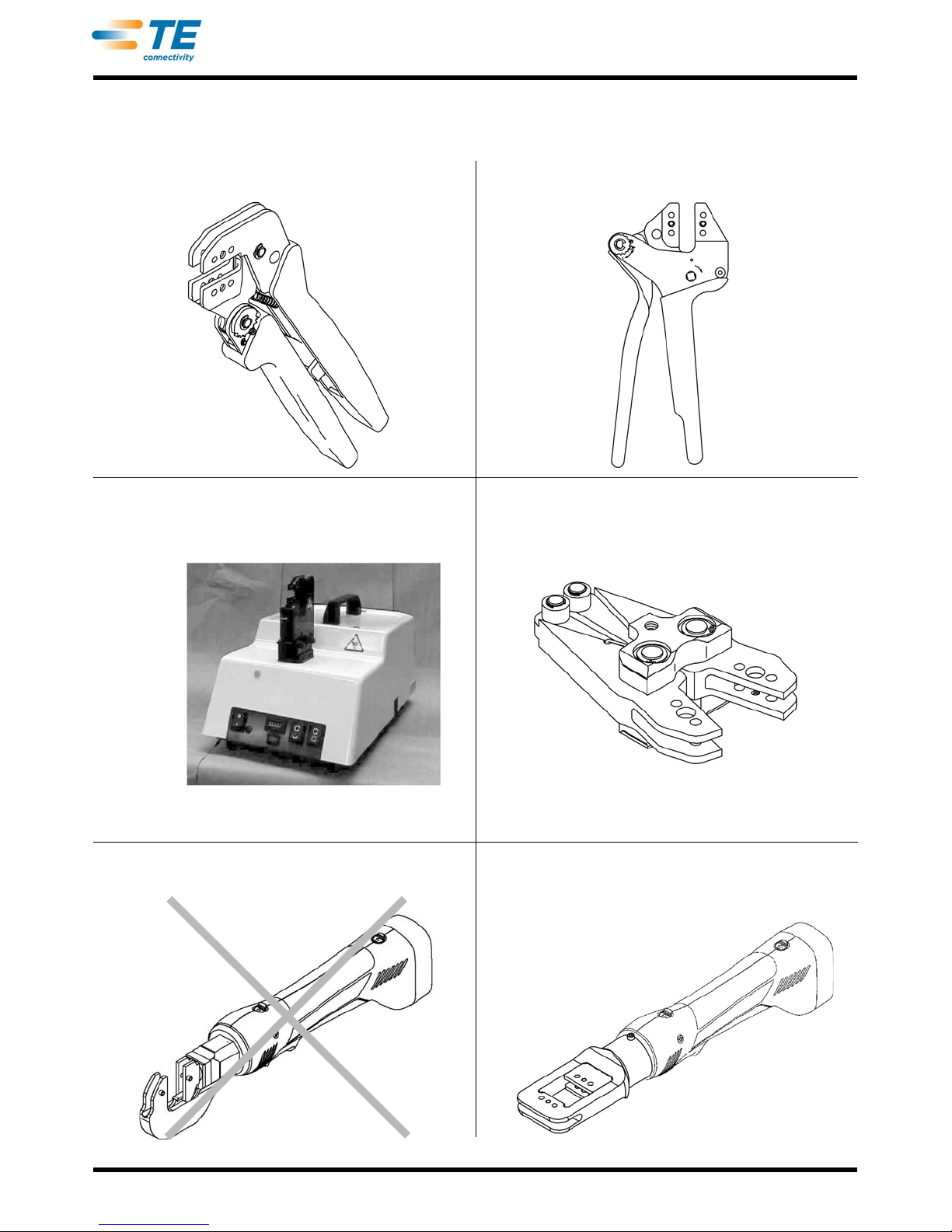
PRO-CRIMPER III Hand Tool Frame 354940-1
(Instruction Sheet 408-9930) SDE-SA Hand Tool 9-1478240-0
(Instruction Sheet 408-8851)
SDE Bench Terminator 1490076-2
(Customer Manual 409-10052) 626 Adapter 679304-1
(Instruction Sheet 408-4070)
Battery Tool (Shouldered Die) 1725837-1, -2
(Customer Manual 409-10053) Battery Tool (Pin Die) 1213890-1, -2
(Customer Manual 409-10065)
Use Die Sets
58517-2 or
58517-4
Use Die Sets
58517-5
Use Die Set 58517-5 Use Die Set 58517-2 or 58517-4
Use Die Set 58517-5
This manual suits for next models
4
Table of contents
Other TE Power Tools manuals


