TE CERTI-CRIMP User manual

Instruction Sheet
1 of 10
© 2016 TE Connectivity family of companies
All Rights Reserved
*Trademark
TE Connectivity, TE connectivity (logo), and TE (logo) are trademarks. Other logos, product, and/or company names may be trademarks of their respective owners.
PRODUCT INFORMATION
1-800-522-6752
This controlled document is subject to change.
For latest revision and Regional Customer Service,
visit our website at www.te.com.
408-1559
11 JAN 16 Rev U
Figure 1
1. INTRODUCTION
CERTI-CRIMP hand crimping tools listed in Figure 1 are used to crimp the products onto the wire listed in
Figure 2.
NOTE
Dimensions in this instruction sheet are in millimeters [with inches in brackets]. Figures and illustrations are for reference only
and are not drawn to scale.
Reasons for reissue of this instruction sheet are provided in Section 7, REVISION SUMMARY.
2. DESCRIPTION (Figure 1)
The handles and label (if applicable) of each tool are color-coded to match the color coding of the product to be
crimped. The tools may show more than one color code.
PRODUCT
COPPER WIRE
TYPE
SIZE RANGE (AWG)
PIDG Terminals and Splices
Solid or Stranded
30-14
PIDG Radiation Resistant Terminals and Splices
Stranded
27-14
PLASTI-GRIP Butt Splices
Solid or Stranded
26-22
PIDG Insulation Restricting Nylon Terminals
Stranded
26-14
PIDG FASTON* Receptacles 641321-1 (.187 Series) and 641324-1 (.110 Series)
Stranded
26-24
PLASTI-GRIP Terminals
Solid or Stranded
22-14
Spare Wire Cap
Stranded
22-14
Figure 2
These tools are members of the CERTI-CRIMP hand crimping tool family. The ratchet ensures full crimping of
the product. Once engaged, the ratchet will not release until the handles have been FULLY closed.
CAUTION
The crimping jaws bottom before the ratchet releases. This design feature ensures maximum tensile performance of the crimp.
DO NOT re-adjust the ratchet.
PROPER USE GUIDELINES
Cumulative Trauma Disorders can result from the prolonged use of manually powered hand tools. Hand tools are intended for occasional use and low
volume applications. A wide selection of powered application equipment for extended-use, production operations is available.
CERTI-CRIMP*
Hand Crimping Tools
Handles
Hand Crimping Tool
Part Numbers
46121
47304
47386
47386-5
47387
47907-1
48518-2
68343-1
69151-1
69454
169485
Ratchet
Label (Color Coded for PIDG*
and PLASTI-GRIP* Products)
Wire Size Range
Stamped Here
Locator
Label (Color Coded
for Sealed Splices)
Jaws
Insulation Crimp Adjustment Pins
(Shown in Position 3)
ORIGINAL INSTRUCTIONS

408-1559
Rev U
2 of 10
3. CRIMPING PROCEDURE
Refer to Figure 3 to ensure that the correct tool and product combination is being used. Figure 3 also lists the
number of dots (or dots and rib) that appear embossed on a crimped product when it is crimped using the
correct tooling.
3.1. PIDG and PLASTI-GRIP Terminal and Splice and PIDG FASTON Receptacle
1. Strip the wire to the dimension provided in Figure 3 being careful to avoid nicking or cutting the
conductor(s).
CAUTION
DO NOT use wire with nicked or missing conductor(s).
2. Open the tool jaws by closing the tool handles until the ratchet releases, then allow the handles to
open fully.
TOOL
PRODUCT
WIRE
PART
NO.
COLOR
CODE
DOT
CODE
DESCRIPTION
INSUL COLOR
SIZE RANGE
(AWG)
INSUL DIA
RANGE
STRIP LENGTH
TERMINAL
SPLICE
46121
169485
Red and
Yellow
1
PIDG Terminals and Splices
Yellow
26-22
---
4.0-4.8
[5/32-3/16]
4.4-5.2
[11/64-13/64]
PLASTI-GRIP Butt Splices
47304●
Yellow
---
PIDG Terminals
47907-1
Blue and
White
2
PIDG Terminals and Splices
Natural Translucent
24-20
---
4.8-6.6
[3/16-7/32]
5.6-6.4
[7/32-1/4]
PIDG Radiation Resistant
Terminals and Splices
Natural Translucent
with White Stripe
47386
47386-5
Red and
Yellow
1
PIDG Terminals
MS 25036-143 through -147
Yellow
26-24
---
5.2-6.0
[13/64-15/64]
---
PIDG Radiation Resistant
Terminals
MS 7928/4-143 through -147
Natural with Yellow
Stripe
47386
47386-5
Red and
Yellow
1
PIDG Terminals and Splices
Red
22-16
---
5.2-6.0
[13/64-15/64]
6.4-7.1
[1/4-9/32]
PLASTI-GRIP Terminals
PIDG Radiation Resistant
Terminals and Splices
Natural Translucent
with White Stripe
69151-1●
Red
---
PIDG Terminals and Splices
Red
22-16
---
5.2-6.0
[13/64-15/64]
6.4-7.1
[1/4-9/32]
PLASTI-GRIP Terminals
PIDG Radiation Resistant
Terminals and Splices
Natural Translucent
with White Stripe
69454
Red
1 Dot
1 Rib
PIDG Terminals and Splices
Red
22-18
---
5.2-6.0
[13/64-15/64]
6.4-7.1
[1/4-9/32]
PLASTI-GRIP Terminals
PIDG Radiation Resistant
Terminals and Splices
Natural Translucent
with White Stripe
47387
Blue and
Green
2
PIDG Terminals and Splices
PLASTI-GRIP Terminals
Blue
16-14
1.04-2.62
[.041-.103]
5.2-6.0
[13/64-15/64]
6.4-7.1
[1/4-9/32]
Green
20-16
HD
0.41-1.65
[.016-.065]
PIDG Radiation Resistant
Terminals and Splices
Natural Translucent
with Blue Stripe
16-14
---
20-16
HD
●Use Tight Insulation Support for Wires with Thin Wall Insulation
Figure 3 (cont’d)

408-1559
Rev U
3 of 10
TOOL
PRODUCT
WIRE
PART
NO.
COLOR
CODE
DOT
CODE
DESCRIPTION
INSUL COLOR
SIZE RANGE
(AWG)
INSUL DIA
RANGE
STRIP LENGTH
TERMINAL
SPLICE
46121
169485
47304●
Red and
Yellow
1
PIDG Insulation Restricting
Nylon Terminals
Yellow with 3
Black Stripes
26
0.66-1.40
[.026-.055]
4.8-5.6
[3/16-7/32]
---
Yellow with 3
Blue Stripes
24
0.79-1.40
[.031-.055]
47386
47386-5
Red and
Yellow
1
PIDG Insulation
Restricting Nylon
Terminals
MS 7928/1-1 through -10
Yellow with 3
Black Stripes
26
0.66-1.40
[.026-.055]
6.4-7.1
[1/4-9/32]
---
Yellow with 3
Blue Stripes
24
0.79-1.40
[.031-.055]
47386
47386-5
69151-1●
Red and
Yellow
Tool
69151-1
Mod F
Red Only
1
PIDG Insulation Restricting
Nylon Terminals
Red with 3
Green Stripes
22
0.97-1.40
[.038-.055]
6.4-7.1
[1/4-9/32]
---
Red with 3
Red Stripes
20
1.17-2.79
[.046-.110]
Red with 3
White Stripes
18
1.42-2.79
[.056-.110]
47387
Blue and
Green
2
PIDG Insulation Restricting
Nylon Terminals
Blue with 3
Blue Stripes
16
1.60-3.30
[.063-.130]
6.4-7.1
[1/4-9/32]
---
47386
47386-5
Red and
Yellow
1
Spare Wire Cap 328307
Red
22-18
---
8.0-8.7
[5/16-11/32]
47387
Blue and
Green
2
Spare Wire Cap 328308
Blue
16-14
---
48518-2
---
---
PIDG FASTON Receptacles
641321-1 (.187 Series) and
641324-1 (.110 Series)
Yellow■
26-24
---
4.8-5.6
[3/16-7/32]
68343-1
6.35
[.250]
Exp.
Blue
2
PLASTI-GRIP Terminals
Blue
16-14
3.81-6.35
[.150-.250]
5.2-6.0
[13/64-15/64]
---
●Use Tight Insulation Support for Wires with Thin Wall Insulation
■For Reference Only – (Check Product-to-Tool Match Using Part Numbers)
Figure 3 (end)
3. Place the product in the jaws as shown in Figure 4 or Figure 5.
4. Close the tool handles until the product is held firmly in place. DO NOT deform the wire barrel.
5. Insert properly stripped wire(s) into the wire barrel as shown in Figure 4 or Figure 5.
CAUTION
DO NOT allow wire insulation to enter the wire barrel.
Figure 4

408-1559
Rev U
4 of 10
6. Complete the crimp by closing the tool handles until the ratchet releases.
7. Release the tool handles, allow the handles to open fully, and remove the crimped product.
8. To crimp the other wire barrel of a splice, re-position the uncrimped wire barrel in the tool as shown in
Figure 5, and repeat Steps 2 through 7.
9. Inspect the crimped product according to Figure 7. Product not meeting these conditions should NOT
be used. If the wire insulation grip is not satisfactory, refer to Section 4 to adjust the grip using the
insulation crimp adjustment pins.
3.2. Spare Wire Cap
1. Strip the wire to the dimension provided in Figure 3, being careful to avoid nicking or cutting the
conductor(s).
CAUTION
DO NOT use wire with nicked or missing conductor(s).
Figure 5
2. Place the tool insulation crimp adjustment pins in Position 3.
3. Close the tool handles until the jaws partially close, but leave enough space for the spare wire cap to
be inserted between the jaws.
4. Raise the locator so that the end of the cap rests against the recessed surface of the locator as shown
in Figure 6.
Figure 6

408-1559
Rev U
5 of 10
5. Close the tool handles until the spare wire cap is held firmly in place. DO NOT deform the wire barrel.
6. Insert a properly stripped wire into the wire barrel until the wire bottoms.
7. Hold the wire in position, and complete the crimp by closing the tool handles until the ratchet releases.
8. Release the tool handles, allow the handles to open fully, and remove the crimped spare wire cap.
9. Inspect crimped product according to Figure 7. Product not meeting these conditions should NOT be
used.
Figure 7

408-1559
Rev U
6 of 10
4. INSULATION CRIMP ADJUSTMENT
The insulation crimp section of the hand tool has three positions: 1 (tight), 2 (medium), and 3 (loose) to adjust
the wire insulation crimp grip. To adjust the insulation grip, proceed as follows:
4.1. PIDG Terminals and Splices and PIDG FASTON Receptacles
NOTE
PIDG terminals and splices feature a wire insulation “grip”.
1. Insert the insulation crimp adjustment pins into Position 3. Refer to Figure 1.
CAUTION
Make sure that both insulation crimp adjustment pins are in the same position.
2. Place a terminal or splice into the tool jaws as shown in Figure 4 or Figure 5.
3. Insert UNSTRIPPED wire into ONLY the insulation barrel of the terminal or splice.
4. Close the tool handles to complete the crimp.
5. Remove the crimped terminal or splice and check the insulation crimp by bending the wire back and
forth once. The terminal or splice should retain its grip on the wire insulation. If the wire pulls out, set
BOTH insulation crimp adjustment pins to the next higher position (2).
6. Perform another crimp, and repeat the adjustment as necessary until the correct insulation grip is
attained. DO NOT use a tighter setting than required.
4.2. PLASTI-GRIP Terminals and Splices
NOTE
PLASTI-GRIP terminals and splices feature a wire insulation “support”. The terminal or splice insulation should ideally be in
contact with the wire insulation.
Set the insulation crimp adjustment pins into position according to the following:
—3 for wire having a large insulation diameter
—2 for wire having a medium insulation diameter
—1 for wire having a small insulation diameter
CAUTION
Make sure that both insulation crimp adjustment pins are in the same position.
5. MAINTENANCE AND INSPECTION
Hand crimping tools are inspected before shipment. The tool received should be inspected immediately upon
arrival to ensure that the tool has not been damaged during shipment, and that it performs according to the
criteria described in this sheet. If a tool is damaged upon arrival, retain the shipping container, file a claim with
the carrier, and notify TE immediately.
5.1. Daily Maintenance
1. Remove dust, moisture, and other contaminants from the tool with a clean brush or a soft, lint-free
cloth. DO NOT use objects that could damage the tool.
2. Make sure that the proper retaining pins are in place and are secured with the proper retaining rings.
3. Make certain that all pins, pivot points, and bearing surfaces are protected with a THIN coat of any
good SAE 20 motor oil. DO NOT oil excessively.
4. When the tool is not in use, keep the handles closed to prevent objects from becoming lodged in the
crimping areas and store the tool in a clean, dry area.
5.2. Periodic Inspection
Regular inspections should be performed by quality control personnel. A record of scheduled inspections
should remain with the tool or be supplied to supervisory personnel responsible for the tool. Though

408-1559
Rev U
7 of 10
recommendations call for at least one inspection per month, the inspection frequency should be based on the
amount of use, working conditions, operator training and skill, and established company standards. These
inspections should be performed in the following sequence:
Visual Inspection
1. Remove all lubrication and accumulated film by immersing the tool (handles partially closed) in a
suitable commercial degreaser that will not affect paint or plastic material.
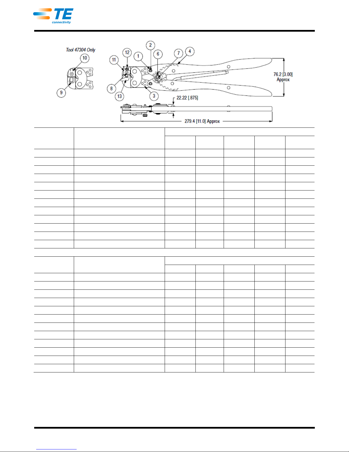
2. Make certain that all retaining pins are in place and are secured with retaining rings. If replacements
are necessary, refer to the parts list in Figure 10.
3. Inspect crimping areas for pitted or chipped surfaces.
4. Close the tool handles until the ratchet releases, then allow handles to open freely. If they do not open
quickly and fully, the spring is defective and must be replaced. Refer to Section 6, REPLACEMENT
AND REPAIR.
Gaging Crimping Chamber
This inspection requires the use of plug gages conforming to the dimensions listed in Figure 8. To gage
the crimping chamber, proceed as follows:
1. Close the jaws by squeezing the tool handles together until the jaws have bottomed, and then HOLD
the handles in this position. DO NOT force the jaws beyond initial contact.
2. Align the GO element of the gage with the wire barrel crimp section of the crimping chamber. Refer to
Figure 9. Push the element straight into the crimping chamber without using force. The GO element
must pass completely through the crimping chamber.
3. Align the NO-GO element of the gage with the same crimp section, and try to insert the element. The
NO-GO element may start entry, but it must not pass completely through the crimping chamber. Refer
to Figure 9.
4. Repeat the gage inspection for the insulation crimp section of the crimping chamber, making sure to
use the correct plug gage.
If the crimping chamber conforms to the gage inspection, the tool is considered dimensionally correct. If
the crimping chamber does not conform to the inspection, the tool must be repaired. Refer to Section 6,
REPLACEMENT AND REPAIR.
For additional information concerning the use of the plug gage, refer to Instruction Sheet 408-7424.
Ratchet Inspection
Obtain a .025-mm [.001-in.] shim that is suitable for checking the clearance between the bottoming
surfaces of the jaws. To inspect the ratchet control, proceed as follows:
1. Refer to Figure 3, and select a product and maximum size wire.
2. Position the product in the crimping chamber according to Paragraph 3.1, Steps 1 through 5 or
Paragraph 3.2, Steps 1 through 6.
3. While holding the wire in place, squeeze the tool handles together until the ratchet releases. Holding
the tool in this position, maintain just enough pressure to keep the jaws closed.
4. Check the clearance between the bottoming surfaces of the jaws. If the clearance is .025 mm
[.001 in.] or less, the ratchet is satisfactory. If clearance exceeds .025 mm [.001 in.], the ratchet is out
of adjustment and must be repaired. Refer to Section 6, REPLACEMENT AND REPAIR. If the tool
conforms to this inspection procedure, lubricate it with a THIN coat of any good SAE 20 motor oil, and
return it to service.
6. REPLACEMENT AND REPAIR
Customer-replaceable parts are listed in Figure 10. Parts other than those listed should be replaced by TE to
ensure quality and reliability. For customer repair service or to order replacement parts, call 1-800-522-6752, or
fax your purchase order to 717-986-7605, or write to: Customer Service (038-035), Tyco Electronics
Corporation, PO Box 3608, Harrisburg, PA 17105-3608.

408-1559
Rev U
8 of 10
7. REVISION SUMMARY
Updated document to corporate requirements
Added dimensional callout in Figure 8
Added new NOTE to Figure 9
TOOL
JAW CLOSURE♦ DIAMETER A
GAGE ELEMENT♦♦ DIAMETER B
DIMENSION
GO
NO-GO
GO
NO-GO
C (WIDTH)
R (RADIUS)
46121
169485
1.600 [.0630]
1.753 [.0690]
1.600-1.608
[.0630-.0633]
1.750-1.753
[.0689-.0690]
---
---
47304
1.600 [.0630]
1.753 [.0690]
1.600-1.608
[.0630-.0633]
1.750-1.753
[.0689-.0690]
47386
47386-5
2.768 [.1090]
2.921 [.1150]
2.768-2.776
[.1090-.1093]
2.918-2.921
[.1149-.1150]
47387
68343-1
3.022 [.1190]
3.175 [.1250]
3.022-3.030
[.1190-.1193]
3.172-3.175
[.1249-.1250]
47907-1
2.260 [.0890]
2.413 [.0950]
2.260-2.268
[.0890-.0893]
2.410-2.413
[.0949-.0950]
48518-2
1.600 [.0630]
1.753 [.0690]
1.600-1.608
[.0630-.0633]
1.750-1.753
[.0689-.0690]
69151-1
2.768 [.1090]
2.921 [.1150]
2.768-2.776
[.1090-.1093]
2.918-2.921
[.1149-.1150]
69454
2.616 [.1030]
2.718 [.1070]
2.616-2.624
[.1030-.1033]
2.715-2.718
[.1069-.1070]
3.962 [.156]
3.454 [.136]
♦Jaw closure dimensions apply when wire barrel jaws are bottomed, but not under pressure. ♦♦Material: Tool Steel
Figure 8 (cont’d)

408-1559
Rev U
9 of 10
TOOL
JAW CLOSURE♦ DIMENSION F
GAGE ELEMENT♦♦ DIMENSION G
DIMENSION W
(WIDTH)
GO
NO-GO
GO
NO-GO
46121
169485
0.762 [.0300]
1.27 [.0500]
0.762-0.77
[.0300-.0303]
1.267-1.27
[.0499-.0500]
3.05 [.120]
47304
0.762 [.0300]
1.27 [.0500]
0.762-0.77
[.0300-.0303]
1.267-1.27
[.0499-.0500]
3.05 [.120]
47386
47386-5
0.762 [.0300]
1.27 [.0500]
0.762-0.77
[.0300-.0303]
1.267-1.27
[.0499-.0500]
3.05 [.120]
47387
1.016 [.0400]
1.524 [.0600]
1.016-1.024
[.0400-.0403]
1.521-1.524
[.0599-.0600]
4.75 [.187]
47907-1
0.762 [.0300]
1.27 [.0500]
0.762-0.77
[.0300-.0303]
1.267-1.27
[.0499-.0500]
2.36 [.093]
48518-2
0.762 [.0300]
1.27 [.0500]
0.762-0.77
[.0300-.0303]
1.267-1.27
[.0499-.0500]
3.05 [.120]
69151-1
0.762 [.0300]
1.27 [.0500]
0.762-0.77
[.0300-.0303]
1.267-1.27
[.0499-.0500]
3.05 [.120]
69454
0.762 [.0300]
1.27 [.0500]
0.762-0.77
[.0300-.0303]
1.267-1.27
[.0499-.0500]
3.05 [.120]
68343-1
1.828 [.0720]
2.337 [.0920]
1.828-1.836
[.0720-.0723]
2.334-2.337
[.0919-.0920]
4.75 [.187]
♦Jaw closure dimensions apply when wire barrel jaws are bottomed, but not under pressure. ♦♦Material: Tool Steel
Figure 8 (end)
Figure 9
W ±0.13 [±.005]
NOTE: Most insulation barrel gages are designed
to check one side of the crimp nest at a time.

408-1559
Rev U
10 of 10
ITEM
DESCRIPTION
PART NUMBER FOR TOOL
46121
47304
47386
47386-5
47387 &
68343-1
1
RING, Retaining
21045-3
21045-3
21045-3
21045-3
21045-3
2
PIN, Retaining
1-23619-6
1-23619-6
1-23619-6
1-23619-6
1-23619-6
3
PIN, Adjustment
39207
39207
39207
39207
39207
4
SPRING
39364
39364
39364
39364
39364
6
RING, Retaining
21045-6
21045-6
21045-6
21045-6
21045-6
7
PIN, Retaining
2-23620-9
2-23620-9
2-23620-9
2-23620-9
2-23620-9
8
SCREW
3-306105-9
3-21016-4
9-305927-1
9-305927-1
9-305927-1
9
SUPPORT
---
39193
---
---
---
10
STOP
---
302765
---
---
---
11
LOCATOR, Housing
302994
---
302994
302994
302994
12
SPRING
301201
---
301201
301201
301201
13
LOCATOR
3-304052-6
---
302993
302993
45965-6
ITEM
DESCRIPTION
PART NUMBER FOR TOOL
47907-1
169485
48518-2
69151-1
69454
1
RING, Retaining
21045-3
21045-3
21045-3
21045-3
21045-3
2
PIN, Retaining
1-23619-6
1-23619-6
1-23619-6
1-23619-6
1-23619-6
3
PIN, Adjustment
39207
39207
39207
39207
39207
4
SPRING
39364
39364
39364
39364
39364
6
RING, Retaining
21045-6
21045-6
21045-6
21045-6
21045-6
7
PIN, Retaining
2-23620-9
2-23620-9
2-23620-9
2-23620-9
2-23620-9
8
SCREW
3-306105-9
3-21016-4
9-305927-1
9-305927-1
9-305927-1
9
SUPPORT
---
---
---
---
---
10
STOP
---
---
---
---
---
11
LOCATOR, Housing
302994
302994
302994
302994
302994-1
12
SPRING
301201
301201
301201
301201
2-304668-6
13
LOCATOR
303542
575960-4
125644-7
302993
4-304052-6
Figure 10
Table of contents
Other TE Power Tools manuals
Popular Power Tools manuals by other brands

Schneider Airsystems
Schneider Airsystems MLH Kfz Original operating manual

POWER8
POWER8 JS05 Jisaw quick start guide

MicroLux
MicroLux 84659 instruction manual

DeWalt
DeWalt DCS355 Original instructions

EIBENSTOCK
EIBENSTOCK EMF 150.1 Original instructions

Bosch
Bosch GDX 14,4 V-LI Professional Original instructions