ETM ETM770-PRO User manual

1
USER
GUIDE
ETM770-PRO
CELLULAR NETWORK MONITORING TOOL
Cat M1/Cat NB/NB2/4G/3G/2G
1802–20220005 Rev PA1, 2022-04-14
Features:
•Cat NB, Cat M1 Connectivity
•4G/3G/2G Connectivity
•GPS Functionality
•Select the most suitable antenna
•OLED display
•Send measured data to EWO server
•Rechargeable battery
•Sleep Mode for super low power
consumption
•Includes antenna, hard case and
charger

2
TABLE OF CONTENTS
1. Buttons, Navigation & Accessories............................................................................................. 3
1.1 Buttons..................................................................................................................................... 3
1.2 Device Navigation.................................................................................................................... 4
1.3 Accessories ............................................................................................................................. 4
2. Device info & settings................................................................................................................... 4
2.1 System..................................................................................................................................... 5
2.2 Settings.................................................................................................................................... 5
3. Scanning signals........................................................................................................................... 6
3.1 Understanding Signal Parameters .......................................................................................... 6
3.2 View, Test & Upload................................................................................................................ 7
4. Configuration tool ......................................................................................................................... 9
Appendix............................................................................................................................................ 10

3
1. BUTTONS, NAVIGATION &
ACCESSORIES
•Insert SIM card as shown in the images above.
IMPORTANT! Make sure the SIM card has PIN code DISABLED!
•To charge the ETM770, insert the charger into the mini USB connector. The battery is
charged with 5V.
•Connect the same cable to a computer if you want to configure the ETM770 using the
configuration tool.
1.1 Buttons
ACTION/BUTTON
EXPLANATION
Restart Device
Alternative 1:
Hold Arrow DOWN + Arrow UP (5 seconds)
Alternative 2:
Navigate (System > Restart Device) in the device menu
Power OFF
Hold Power button (bottom left corner) 3 seconds
Sleep mode
Hold Power button more than 5 seconds
OK Button
Action button/Forward navigation in menu
Arrow Up
Menu navigation/Backwards button when at the top of the menu
Arrow Down
Menu navigation

4
1.2 Device Navigation
Use this guide to easily navigate through the device to perform different actions. Basic
functionality is described further down the document.
1.3 Accessories
•The ETM770 comes with a carrying case containing USB cable for
programming/charging, charging brick, power adapters, car charger and quick start
guide.
2. DEVICE INFO & SETTINGS
SMS COMMANDS
EXPLANATION AND EXAMPLE
ET-IP1=”IP Address”:”Port”
Change the server address
Example: ET-IP1=54.77.219.177:7162 (EWO server)
ET-IP3=”IP Adress”:”Port”
Change the PING adress
Example: ET-IP3=8.8.8.8:80 (Google)
ETSAPN=“List position”, “APN
name”
Change APN list
Example: ETSAPN=1,m2m.tele2.com
ETSUP=“List position”,
“Username”, “Password”
Change User/Password
Example: ETSUP=1,username1,password23

5
2.1 System
Device Data
Firmware version (TOP)
Hardware number (HW#)
IMEI Number
Date and Time
Module Temperature
Supply Volage
Battery Voltage
Rolling network Information
Server Adress
Add a server to receive data being sent from the device. This can be configured in the configuration
tool shown below or via SMS command shown above.
Check for Firmware (FW) Updates
Device will connect to the internet to check if the firmware is up to date.
Restart Device
Restart the device without using the hardware buttons
2.2 Settings
Select APN & Select User/PassW
Select which APN to use. APN can be added using the configuration tool shown below, or via SMS
command shown above. The same thing applies to Select User/PassW
Logging
This is where you activate continuous logging and sending as well as GPS. Make sure you have a
server address added for receiving data. Check this by navigating system →server address
6
3. SCANNING SIGNALS
*Use “1.2 Device Navigation” above for help if you need.
Step 1: Select Radio Bands
Broaden or narrow down your network scanning to only the bands you wish to scan
Step 2: Scan for available operators
This might take a few minutes. The device displays all operators it can find in your area together with a
network technology (e.g. 4G or M1)
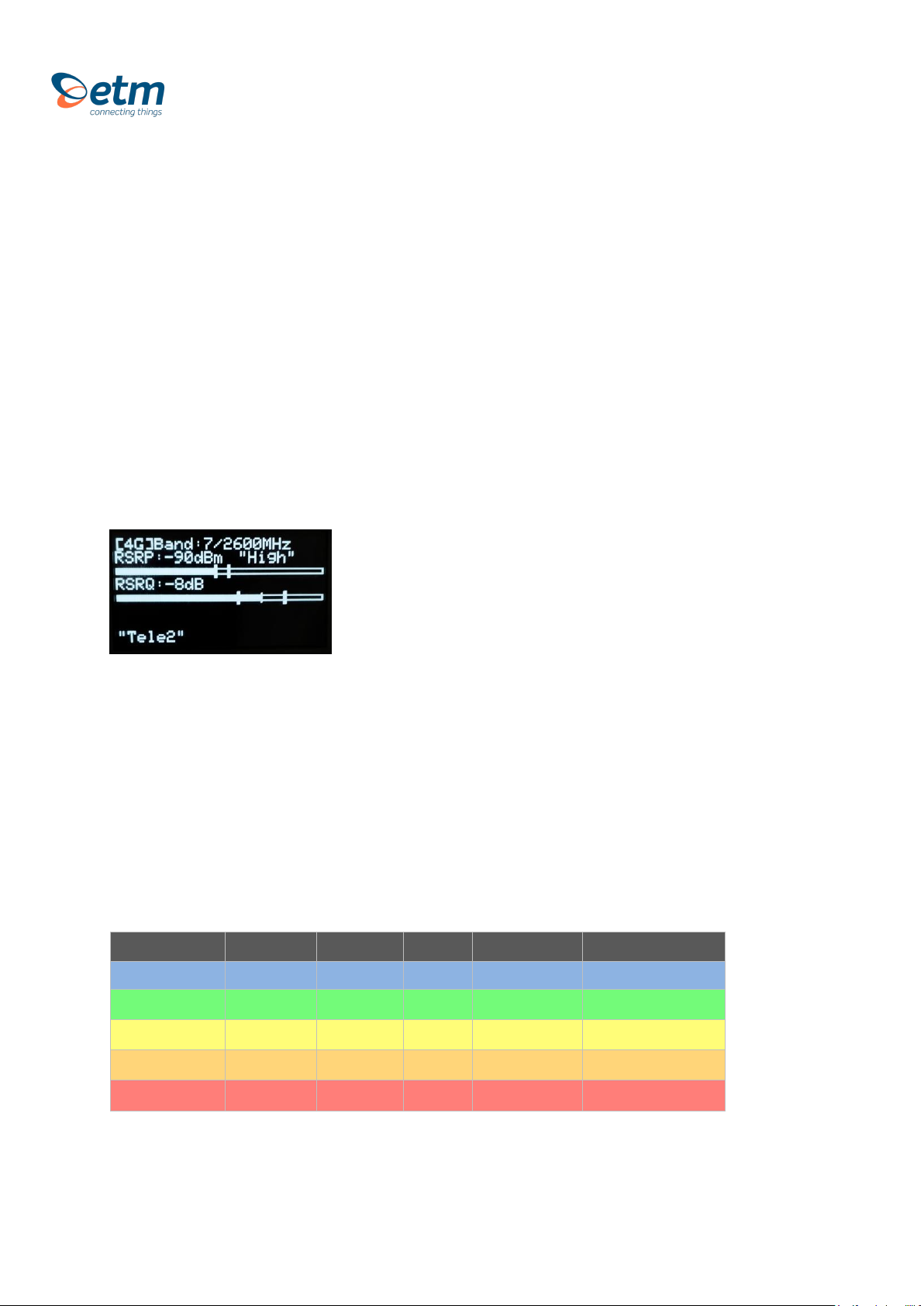
Step 3: Scanning a signal
Explanation
•The device is connected to a 4G band. The band is 7 and the frequency is 2600 MHz.
•Reference Signal Received Power (the signal strength without noise and interference)
measured in dBm. The signal is visualized in the signal bar below the data.
•Reference Signal Received Quality (how well the signal is coded) measured in dB. The signal
is visualized in the signal bar below the data.
•In the bottom shows rolling information about PLMN & Band, Operator, RSSI, Status
3.1 Understanding Signal Parameters
PARAMETER
RSSI
SINR
RSRQ
RSRP
EC/IO
Technology
LTE & 3G
LTE
LTE
LTE
HSPA+ & EVDO
Excellent
> -65
> 12,5
> -5
> -84
> -2
Good
-65 to -75
10 to 12.5
-9 to -5
-85 to -102
-2 to -5
Fair
-75 to -85
7 to 10
-12 to -9
-103 to -111
-5 to -10
Poor
< -85
< 7
< -12
< -111
<-10
7
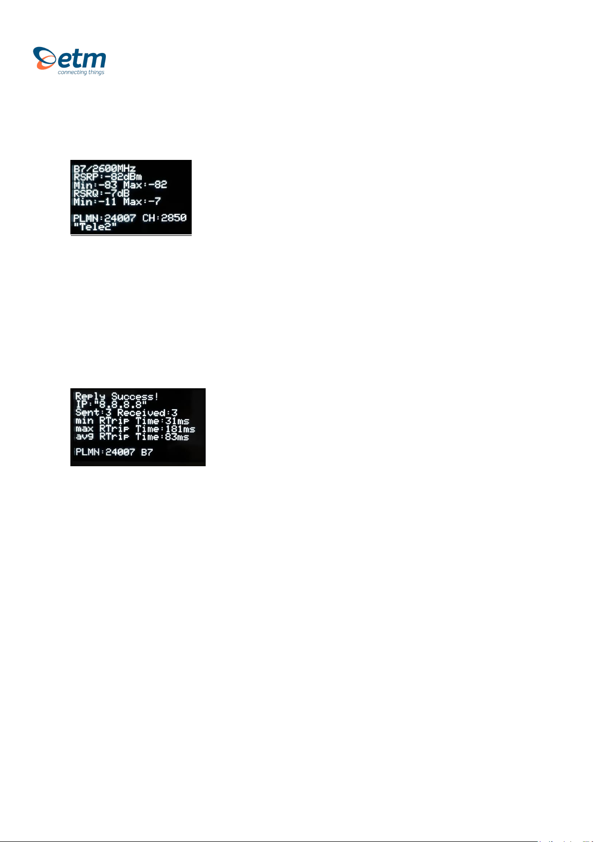
3.2 View, Test & Upload
Explanation
•Band 7 / 2600 Mhz
•Referenced Signal Received Power (RSRP) is -82 dBm with Min & Max values below
•Referenced Signal Received Quality (RSRQ) is -7dB with Min & Max values below
•Public Land Mobile Network (PLMN) is 240007: The channel is 2850
•Scanned Network (Operator)
Communication test
Ping to test network communication. Standard is set to Google’s server. This can be change using the
configuration tool shown below.
Upload Signal
1. Uploading a signal is made through pushing “Send Data to Server”. Make sure you have IP +
Port setup. You can easily add this by sending a SMS command seen above in “2.1 SMS
Commands”
2. Uploading signals continuously without pushing can be done through activating logging and
sending under settings.
Download Signal
If logging is turned on while sending is turned off, the logged scans will be stored on the device. They
can be downloaded using the configuration tool explained further down the manual

8
Current Network Data (4 pages)
*Press Arrow Down to access next page
Basic network data information.
Abbreviations described under appendix below
Neighboring cells
SIM Status, Network Status, Net Provider and
APN and LIP (Local IP Adress)

9
4. CONFIGURATION TOOL
•Another way of configuring your ETM770 is by using the configuration tool. Begin by
downloading the latest configuration tool located under Resources on
https://etmiot.com/. Proceed by connecting the unit to a computer with the provided
USB charging cable.
1. Start the configuration tool and connect the device to a PC running Windows
2. Go to the terminal tab, use “Set COM Port” to choose the right COM port (see device
manager →Ports (COM & LPT)) in Windows. When correct port is selected, set
baud rate to 115200.
3. Open the port by pressing “COM(X): CLOSED”
4. Click anywhere in the black terminal window until you see a flashing square. Proceed by
restarting the unit by either holding down arrow UP and DOWN for 5 seconds, or write
“ETESC” in the command window.
5. Make sure that the firmware matches the configuration tool version unlike the picture above
(Should be CT0980 on both positions, not like CT0950 in this case)
1. When done configuring the unit, press the red button “WRITE MEMORY” to upload the
configuration to the unit
2. To see what configuration is already on the unit, press “READ MEMORY” when having the
unit connected to the computer to read it onto the configuration tool.
3. To save your configuration to use for future units, press “File” in the top left corner, then
“save” in the dropdown menu, and save the file to an optional location. Your device is now
ready to be configured.
3.
3.
4.
5.
6.
6.
3.
2.
1.

10
Appendix
1. Table below shows a brief explanation of the 3G network abbreviations.
ABBREVIATION
FULL NAME
FURTHER EXPLANATIONS
CHANN
CHANNEL
Shows the ARFCN (Absolute Frequency Channel Number) of the Radio Band
Frequency.
PSC
Primary Synchronization
Code
Describes start and stop time for the time slot that the device has been allocated.
MCC
Mobile Country Code
The first part of the PLMN code.
MNC
Mobile Network Code
The second part of the PLMN code.
EC/n0
Carrier to Noise Ratio
LAC
Local Area Code
CELL
CELL ID
Cell identification number
APN
Access Point Name
This will only be useful information if you have set up an ISP connection.
LIP
Local IP
This will only be useful information if you have set up an ISP connection.
RSCP
Received Signal Code
Power
Measured in dBm
SQ
Signal Quality
Quality value for base station selection in dBm
SRxL
RX level value for base station selection indBm

11
2. Table below shows a brief explanation of the 4G network abbreviations.
ABBREVIATION
FULL NAME
FURTHER EXPLANATIONS
EARFCN
CHANNEL
E-UTRA Absolute Radio Frequency Channel Number
B (Band)
Frequency Band
E-UTRA frequency band
DL
DL bandwidth
DL bandwidth
UL
UL bandwidth
UL bandwidth
Mode
Duplex Mode
TimeDivisionDuplex (TDD) or FrequencyDivisionDuplex (FDD)
MCC
Mobile Country Code
The first part of the PLMN code.
MNC
Mobile Network Code
The second part of the PLMN code.
TAC
Tracking Area Code
GCID
Global Cell ID
Global Cell ID
PhyC ID
Physical Cell ID
Physical Cell ID
SQ
Signal Quality
Quality value for base station selection in dBm
RSRP
Reference Signal Received Power
RSRQ
Reference Signal Received Quality
RSSI
Reference Signal Strength Indication
Note: A PLMN is identified by the Mobile Country Code (MCC) and the Mobile Network Code (MNC)
ETM Mätteknik AB
Ekbacksvägen 32, SE-168 69 Bromma, Sweden
Tel: +46 (0)8 25 28 75 Fax: +46 (0)8 80 11 10
ETM Pacific Pty Ltd
Suite 6, 273 Alfred Street, North Sydney NSW 2060, Australia
Tel: +61 (0)2 9956 7377 Fax: +61 (0)2 9956 5791
Table of contents
Other ETM Measuring Instrument manuals


