TABLE
OF
CONTENTS
21
3
1.
Test
Equipment
Required
4
2.
Specifications
&
Service
Data
6
3.
Parts
ocation
24
6-3-5.
32
33
Block
Diagram
16
7.
5-8.
evel
Diagram
34
8.
Trouble-Shooting
35
9.
2
5-9.
5-10.
5-11.
5-12.
5-13.
5-14.
19
20
16
16
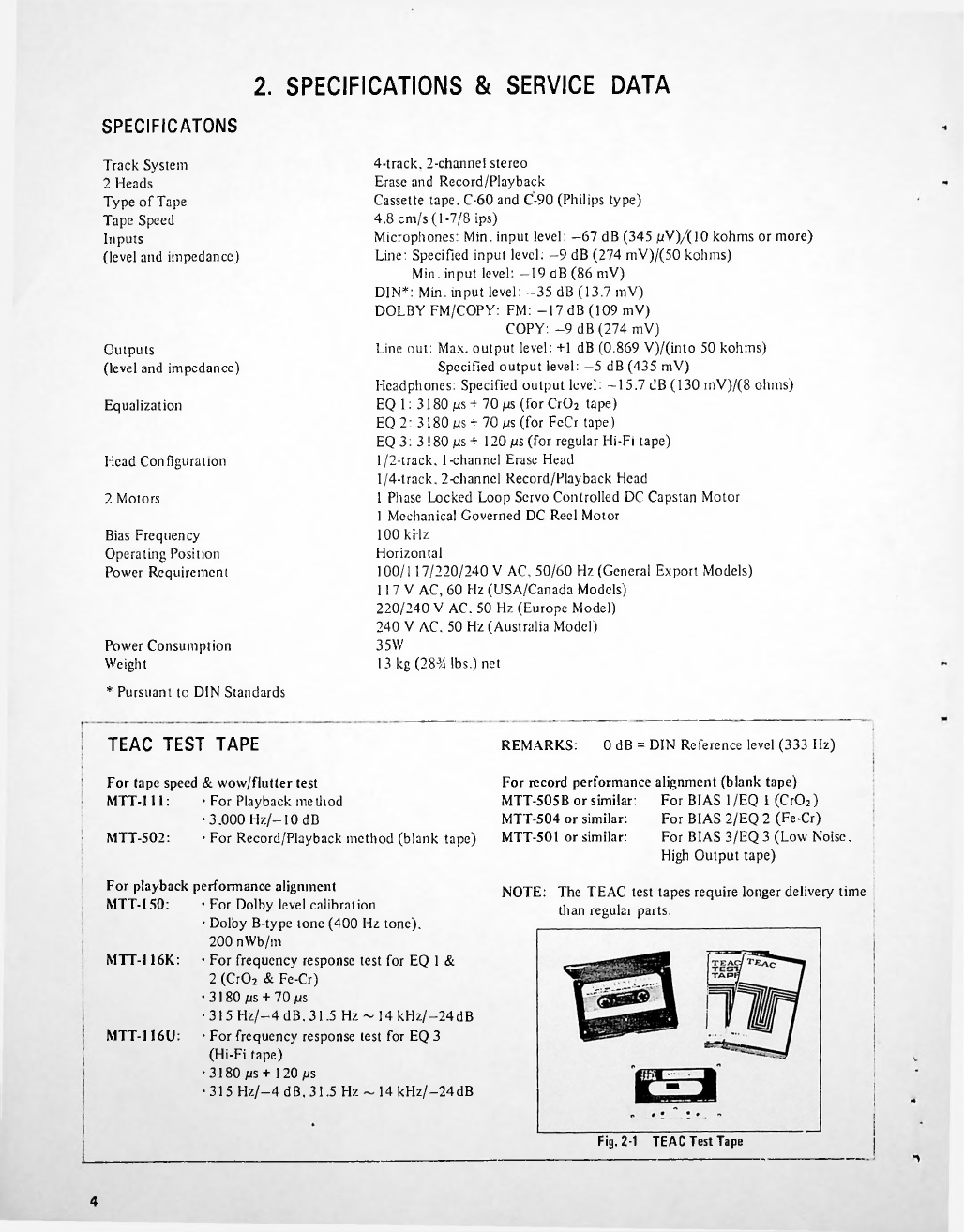
TEAC
Test
Tape
ubrication
............................................
Torque
Measurement
using
the
Cassette
Torque
Meter
Visual
Index
(for
5-6,
7,
8,
11
Sections)
Voltage
and
Frequency
Setting
Playback
Performance
Record/Playback
Head
Azimuth
Adjustments
................................
Specified
Output
evel
Setting
.
.
Frequency
Response
-Playback-
.
.
Signal
to
Noise
Ratio
-Playback-
.
5
11
13
15
17
7
7
7
7
8
8
8
9
9
10
10
11
11
4-1.
4-2.
4-3.
4-4.
4-5.
4-6.
4-7.
4-8.
4-9.
4-10.
4-11.
4-12.
6-2.
6-2-1.
25
25
25
26
27
27
28
28
29
29
30
31
6-2-2.
6-2-3.
6-2-4.
6-2-5.
6-2-6.
6-3.
6-3-1.
6-3-2.
6-3-3.
6-3-4.
5-1.
5-2.
5-3.
54.
5-5.
5-5-1.
5-5-2.
5-6.
5-7.
12
12
12
13
13
14
14
14
15
6-4.
6-4-1.
6-4-2.
6-4-3.
6-4-4.
6-4-5.
6-4-6.
6-4-7.
6-4-8.
6-4-9.
.
.
21
.
.
22
22
.
.
23
VU
Meter
Calibration
-Playback-
....
23
Headphone
Output
evel
Checks
....
23
Monitor
Performance
24
Minimum
Input
evel
Checks
24
Specified
INE
Control
Setting
24
VU
Meter
Calibration
-Record-
24
ED
Peak
evel
Indicator
Calibration
DO BY
NR
COPY-OUT-FM
Switch
Function
Check
Recording
Performance
Bias
Trap
Adjustments
Record
Bias
Setting
Record
evel
Setting
Distortion
Checks
Frequency
Response
-Overall-
.
Signal
to
Noise
Ratio
■
Overall-
Dolby
NR
Effect
Measurement
Peak
imiter
Efficiency
Checks
Erase
Efficiency
6-4-10.
Channel
Separation
6-4-11.
Adjacent
Track
Crosstalk
Measurement
4.
Partial
Disassembly
of
Main
Parts
Case/Front.Panel
Tape
Transport
Chassis
Removal
.
.
.
Partial
Rotation
of
Front
Chassis
.
.
.
Head
Pinch
Roller
Cassette
Holder
Capstan
Motor
Capstan
Drive
Ass
’
y/Drive
Belt
.
.
.
.
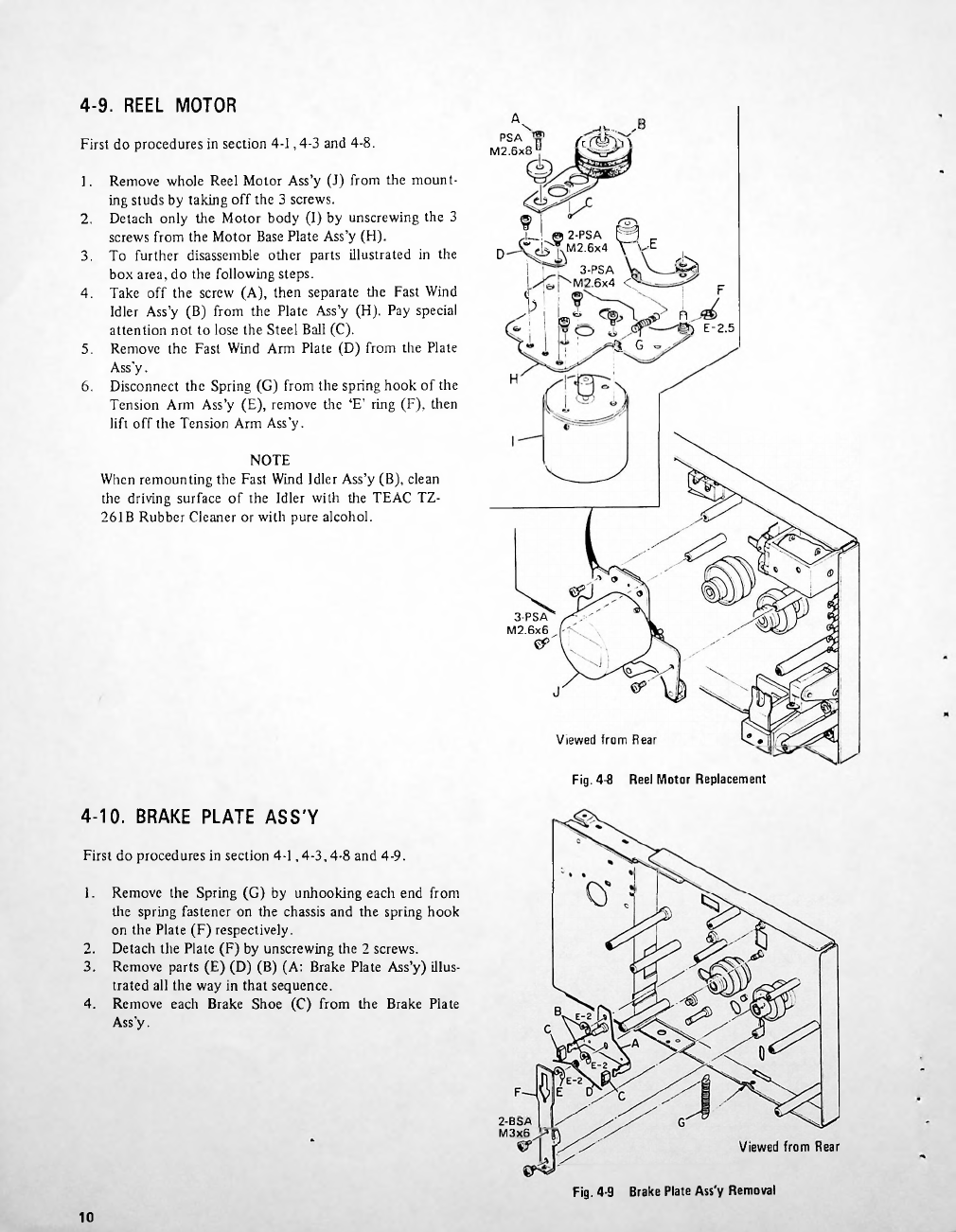
Reel
Motor
.......................................
Brake
Plate
Ass'y
Reel
Tables
........................................
Idler
Ass
’
y
5.
Mechanical
Checks
and
Adjustments
Take-up
Torque
.................
Fast
Forward
&
Rewind
Torque
.
.
.
Pinch
Roller
Pressure
Brake
Tension
Tape
Speed/Wow
and
Flutter
Tape
Speed
Wow
and
Flutter
Flywheel
Bearing
Adjustment
CASSETTE
IN
Switch
Position
Adjustment
RECORD
SAFETY
Switch
Position
Adjustment
Cassette
Holder
Motion
Checks
....
Oil
Retaining
Washer
Clearance
Check
16
Eject
ock
ever
Adjustment
17
Pushbutton
Control
Checks
18
Auto-End
Stop
Facility
Check
19
Memory
Device
Function
Checks
....
19
6.
Electrical
Checks
and
Adjustments
6-1.
Adjustment
ocation