Teal SMA SUNNY MULTIGATE XT User manual

TEAL PN 1060147 | Models Multigate XT1 to XT4 | Revision 2.5
SUNNY MULTIGATE XT
Installation Manual
US
Designed and Manufactured by TEAL Electronics

Installation Manual - TEAL PN 1060147 rev 2.52
TEAL Electronics SMA America, LLC

Installation Manual - TEAL PN 1060147 rev 2.5 3
TEAL Electronics SMA America, LLC
Copyright © 2013 TEAL Electronics. All rights reserved.
Some portions of this document are protected under Copyright © 2012 and 2013 SMA
America,LLC. All rights reserved.
No part of this document may be reproduced, stored in a retrieval system, or transmitted, in any
formor by any means, electronic, mechanical, photographic, magnetic or otherwise, without the
prior written permission of SMA America,LLC and TEAL Electronics.
Neither SMA America,LLC nor TEAL Electronics makes representations, express or implied,
with respect to this documentation or any of the equipment and/or software it may describe,
including (with no limitation) any implied warranties of utility, merchantability, or fitness for any
particular purpose. All such warranties are expressly disclaimed. Neither SMA America,LLC nor
its distributors or dealers nor TEAL Electronics nor its distributors or dealers shall be liable for any
indirect, incidental, or consequential damages under any circumstances.
(The exclusion of implied warranties may not apply in all cases under some statutes, and thus the
above exclusion may not apply.)
Specifications are subject to change without notice. Every attempt has been made to make this
document complete, accurate and up-to-date. Readers are cautioned, however, that
SMAAmerica,LLC and TEAL Electronics reserve the right to make changes without notice
and shall not be responsible for any damages, including indirect, incidental or consequential
damages, caused by reliance on the material presented, including, but not limited to, omissions,
typographical errors, arithmetical errors or listing errors in the content material.
All trademarks are recognized even if these are not marked separately. Missing designations do
not mean that a product or brand is not a registered trademark.
SMA America, LLC
3801 N. Havana Street
Denver, CO 80239 U.S.A.
TEAL Electronics
10350 Sorrento Valley Road
San Diego, CA 92121 U.S.A.

Installation Manual - TEAL PN 1060147 rev 2.54
TEAL Electronics SMA America, LLC
IMPORTANT SAFETY INSTRUCTIONS
SAVE THESE INSTRUCTIONS
This manual contains important instructions for the Multigate XT enclosure product family.
This manual must be followed during installation and maintenance.
The products are designed and tested according to international safety requirements, but as with
all electrical and electronic equipment, certain precautions must be observed when installing and/
or operating the products. To reduce the risk of personal injury and to ensure the safe installation
and operation of the products, you must carefully read and follow all instructions, cautions and
warnings in this manual.
Warnings in this document
A warning describes a hazard to equipment or personnel. It calls attention to a procedure or practice,
which, if not correctly performed or adhered to, could result in damage to or destruction of part or all
of the SMA equipment and/or other equipment connected to the SMA equipment or personal injury.
SymbolDescription
DANGER indicates a hazardous situation which, if not avoided, will result
in death or serious injury.
WARNING indicates a hazardous situation which, if not avoided, could
result in death or serious injury.
CAUTION indicates a hazardous situation which, if not avoided, could
result in minor or moderate injury.
NOTICE is used to address practices not related to personal injury.
Installation Manual - TEAL PN 1060147 rev 2.5 5
TEAL Electronics SMA America, LLC
Product markings
The following symbols are used as product markings with the following meanings.
Symbol Description
Warning regarding dangerous voltage
The product works with high voltages. All work on the product must
only be performed as described in the documentation of the product.
Observe the operating instructions
Read the documentation of the product before working on it.
Follow all safety precautions and instructions as described in the
documentation.
UL-1741 is the standard applied by Underwriters Laboratories to the
product to certify that it meets the requirements of the
National ElectricalCode®.
UL-61010-1 is the standard applied by Underwriters Laboratories
to specify Electrical Equipment For Measurement, Control, and
Laboratory Use.
The product has been certified by Intertek as being in accordance
with the applicable directives.
FCC Information:
This equipment has been tested and found to comply with the limits for a Class B digital
device, pursuant to part 15 of the FCC Rules. These limits are designed to provide
reasonable protection against harmful interference in a residential installation. This
equipment generates, uses and can radiate radio frequency energy and, if not installed
and used in accordance with the instructions, may cause harmful interference to radio
communications. However, there is no guarantee that interference will not occur in a
particular installation. If this equipment does cause harmful interference to radio or
television reception, which can be determined by turning the equipment off and on,
the user is encouraged to try to correct the interference by one or more of the following
measures:
—Reorient or relocate the receiving antenna.
—Increase the separation between the equipment and receiver.
—Connect the equipment into an outlet on a circuit different from that to which the
receiver is connected.
—Consult the dealer or an experienced radio/TV technician for help.
Additional product information

Installation Manual - TEAL PN 1060147 rev 2.56
TEAL Electronics SMA America, LLC
General Warnings
General Warnings
All electrical installations must be done in accordance with the local and
NationalElectrical Code®or ANSI/NFPA 70. This document does not and is not
intended to replace any local, state, provincial, federal or national laws, regulation
or codes applicable to the installation and use of the product, including without
limitation applicable electrical safety codes. All installations must conform with the
laws, regulations, codes and standards applicable in the jurisdiction of installation.
Neither SMA nor TEAL assumes responsibility for the compliance or noncompliance
with such laws or codes in connection with the installation of the product.
The product contains no user-serviceable parts. For all repair and maintenance,
always contact an authorized SMA Service Center.
Before installing or using the product, read all of the instructions, cautions, and
warnings in this manual.
Before connecting the product to the electrical utility grid, contact the local utility
company. This connection must be made only by qualified personnel.
Wiring of the product must be made by qualified personnel only.

Installation Manual - TEAL PN 1060147 rev 2.5 7
TEAL Electronics SMA America, LLC
Table of Contents
Table of Figures................................... 8
1 Information on this Document ........................ 9
2 Safety .......................................... 10
2.1 Intended Use ........................................... 10
2.2 Skills of Qualified Persons.................................. 11
2.3 Safety Precautions ....................................... 12
3 Scope of Delivery ................................. 13
4 Product Description ................................ 14
4.1 Multigate XT ........................................... 14
4.2 Multigate XT Models ..................................... 14
4.3 Type Label and Stickers ................................... 20
4.4 Communication ......................................... 22
5 Mounting ....................................... 23
5.1 Selecting the Multigate XT Mounting Location .................... 23
5.2 Mounting the Multigate XT.................................. 24
5.3 Mounting and Dimensional Details ............................ 25
6 Electrical Connection ............................... 31
6.1 Safety during Electrical Connection ........................... 31
6.2 Connection Areas ....................................... 32
6.2.1 Multigate XT1E ..........................................34
6.2.2 Multigate XT2E ..........................................35
6.2.3 Multigate XT2S ......................................... 36
6.2.4 Multigate XT3S ......................................... 37
6.2.5 Multigate XT4S ......................................... 38
7 Product Specifications .............................. 39

Installation Manual - TEAL PN 1060147 rev 2.58
TEAL Electronics SMA America, LLC
Table of Figures
1Design of a PV plant with Sunny Boy 240-US and Multigate XT ............. 10
2Elements included in the scope of delivery of the Multigate XT .............. 13
3 Multigate XT1E........................................... 14
4 Multigate XT1E shown with touch-safe cover removed ................... 15
5 Multigate XT1E shown with touch-safe door open and touch-safe cover in place ....15
6Multigate XT2E ........................................... 16
7Multigate XT2E shown with touch-safe cover removed ................... 16
8 Multigate XT2S........................................... 17
9 Multigate XT2S shown with touch-safe cover removed ................... 17
10 Multigate XT3S........................................... 18
11 Multigate XT3S shown with touch-safe cover removed ................... 18
12 Multigate XT4S........................................... 19
13 Multigate XT4S shown with touch-safe cover removed ................... 19
14 Example of the Multigate XT Type Label ........................... 20
15 Example of the PIC/RID Label supplied with each Multigate ............... 21
16 Example of the Multigate XT Door Label ...............................21
17 Example of a PV plant with micro inverters and Multigate XT with network
connection via Speedwire/Webconnect............................ 22
18 Multigate XT wall mounted in the vertical position, conrmed by SMA Logo
label located in upper right corner of mounted unit..................... 24
19 Multigate XT wall mounting kit, included with each Multigate XT .............24
20 Multigate XT wall mounting kit, shown installed on Multigate XT .............24
21 Dimensions of the Multigate XT1E ............................... 25
22 Mounting Dimensions of the Multigate XT1E ......................... 26
23 Dimensions of the Multigate XT2E and XT2S......................... 27
24 Mounting Dimensions of the Multigate XT2E and XT2S .................. 28
25 Dimensions of the Multigate XT3S and XT4S......................... 29
26 Mounting Dimensions of the Multigate XT3S and XT4S .................. 30
27 XT1E Input Wiring......................................... 34
28 XT1E Connections ......................................... 34
29 XT2E Speedwire Connections.................................. 35
30 XT2E Connections ......................................... 35
31 XT2S Speedwire Connections.......................................36
32 XT2S Connections ......................................... 36
33 XT3S Speedwire Connections.................................. 37
34 XT3S Connections ......................................... 37
35 XT4S Speedwire Connections.................................. 38
36 XT4S Connections ......................................... 38

Installation Manual - TEAL PN 1060147 rev 2.5 9
TEAL Electronics SMA America, LLC
1 Information on this Document
Validity
This document is valid for the following device types:
•MG-XT1E-US-10 - referred to as Multigate XT1E
•MG-XT2E-US-10 - referred to as Multigate XT2E
•MG-XT2S-US-10 - referred to as Multigate XT2S
•MG-XT3S-US-10 - referred to as Multigate XT3S
•MG-XT4S-US-10 - referred to as Multigate XT4S
Target Group
This document is intended for qualified persons. Only personnel with the appropriate skills
are allowed to perform the tasks set forth in this document (see section 2.2 “Skills of Qualified
Persons”, page 11).
Additional Information
Links to additional information can be found at www.SMA-Solar.com:
Document title Document type
Micro Inverters in Sunny PortalUser manual
Sunny Explorer User manual
Sunny Boy 240-US / Sunny
Multigate-US
Installation manual
Nomenclature
Complete designation Designation in this document
SMA America Production, LLCSMA
SMA Solar Technology Canada Inc.SMA
SMA Speedwire/Webconnect Speedwire/Webconnect
Sunny Boy 240-US* Sunny Boy, inverter, micro inverter*
Sunny Multigate-US Sunny Multigate
* The terms “Sunny Boy”, “Sunny Boy 240-US”, “micro inverter” and “inverter” are synonymous in this document.
Installation Manual - TEAL PN 1060147 rev 2.510
TEAL Electronics SMA America, LLC
2 Safety
2.1 Intended Use
Multigate XT
The Multigate XT is an outdoor rated enclosure containing between 1 and 4 Sunny
Multigates, associated terminal blocks for inputs from each string of Sunny Boy micro
inverters, associated terminal blocks for outputs of each Sunny Multigate to the AC
Grid connection point, and associated hardware for Speedwire/Webconnect (related to
Ethernet) connection for monitoring system performance over the internet.
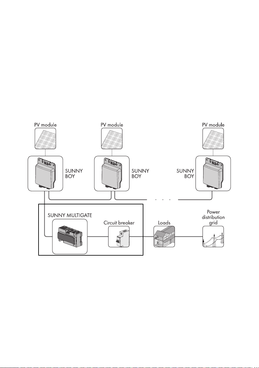
Figure 1: Design of a PV plant with Sunny Boy 240-US and Multigate XT
The Multigate XT contains between 1 to 4 Sunny Multigates, each of which are a
communication unit that forms the connection point of the PV plant with a maximum
of twelve micro inverters to the utility grid. The Multigate XT is connected between the
Sunny Boy 240-US micro inverter and the utility grid to feed the alternating current
converted by the inverters collectively into the utility grid. The Multigate XT is designed
for split-phase operation only. The Multigate XT must be operated in conjunction with
SMA Sunny Boy 240-US.
Multigate XT

Installation Manual - TEAL PN 1060147 rev 2.5 11
TEAL Electronics SMA America, LLC
The Multigate XT is designed in a dust-tight and water-tight industrial enclosure
complying with the fire protection class 5VA and pollution degree 3. The enclosure must
comply at a minimum with UL50 Type 3 when conduits are installed.
For safety reasons, it is forbidden to modify the product or install components that are
not explicitly recommended for this product.
Only use the Multigate XT in accordance with the information provided in the enclosed
documentation. Any other use can result in personal injury or property damage.
• Each Multigate XT contains from 1 to 4 Sunny Multigates. The model number
designation contains the number of Sunny Multigates in each Multigate XT. Model
XT1 contains 1 Sunny Mulitgate. Model XT2 contains 2 Sunny Multigates. Model
XT3 contains 3 Sunny Multigates. Model XT4 contains 4 Sunny Multigates.
• A maximum of twelve micro inverters can be connected to each Sunny Multigate.
• No loads may be connected between the Sunny Multigate and the circuit breaker.
• The grounding conductor of the AC cable from the inverter must be connected to the
corresponding Sunny Multigate grounding terminal in the Multigate XT.
• The output grounding conductor of the Multigate XT must be connected to the
equipotential bonding of the AC distribution board.
• The Sunny Multigate must not be opened.
The enclosed documentation is an integral part of this product.
• Read and observe the documentation.
• Keep the documentation in a convenient place for future reference.
2.2 Skills of Qualified Persons
The tasks described in this document must be performed by qualified persons only.
Qualified persons must have the following skills:
• Knowledge of how an inverter works and is operated
• Training in how to deal with the dangers and risks associated with installing and
using electrical devices and plants
• Training in the installation and commissioning of electrical devices and plants
• Knowledge of the applicable standards and guidelines
• Knowledge of and observance of this document and all safety precautions

Installation Manual - TEAL PN 1060147 rev 2.512
TEAL Electronics SMA America, LLC
2.3 Safety Precautions
Str
Danger to life from electric shock due to high voltages
In the live components of the Multigate XT, high voltages are present that can cause
fatal electric shocks if touched.
• Do not open the Sunny Multigate.
• Do not touch any live components of the Multigate XT.
• Prior to performing any work on the Multigate XT, disconnect it from any voltage
sources.
• Observe the safety messages on the inverter and the Sunny Multigate.
Danger to life from electric shock due to ground fault
If a ground fault has occurred, parts of the plant that are supposedly grounded may
in fact be live. Death or serious injuries can occur from contact with live components.
• Prior to touching any components, always disconnect the Multigate XT from any
voltage sources.
Danger to life from electric shock due to damaged devices
Operating a damaged Multigate XT can lead to hazardous situations that result in
death or serious injuries due to electric shock.
• Only operate the Multigate XT providing that it is in safe and full working order.
• Regularly check for visible damage.
Damage to the Multigate XT from moisture and dust intrusion
Dust or moisture intrusion can damage the Multigate XT and impair its functionality.
The Multigate XT must always be installed in compliance with UL50E. This ensures
that the Sunny Multigate is protected against dust and moisture and is suitable for
indoor and outdoor operation.
•The Multigate XT must be installed in compliance with a Type 4 industrial
enclosure with pollution degree 3.
•Use only conduit fittings, hubs, or connectors that also meet the requirements of
a Type 4 industrial enclosure with pollution degree 3.
Installation Manual - TEAL PN 1060147 rev 2.5 13
TEAL Electronics SMA America, LLC
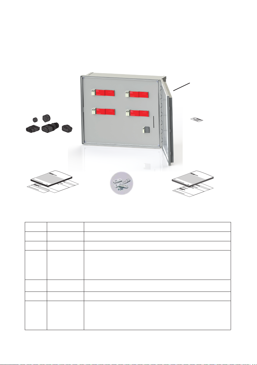
3 Scope of Delivery
Check the scope of delivery for completeness and any externally visible damage. Contact your
specialty retailer if the scope of delivery is incomplete or damaged.
Multigate XT
Figure 2:Elements included in the scope of delivery of the Multigate XT
ItemQuantityDesignation
A1Multigate XT (Model Specific)
B1Enclosure Wall Mount Kit
C1 for XT1
2 for XT2
3 for XT3
4 for XT4
Multigate Accessory Kit - Quantity varies by model -
Connection Terminals for micro inverter connection to input
cabling of the Multigate XT
D1Installation Manual for Multigate XT
E 1 Installation Manual for Sunny Boy 240-US / Multigate-US
F1 for XT1
2 for XT2
3 for XT3
4 for XT4
PIC and RID Labels - Quantity varies by model - For logging
the PIC and RID numbers during installation
B
A
D
C
E
F

Installation Manual - TEAL PN 1060147 rev 2.514
TEAL Electronics SMA America, LLC
4 Product Description
4.1 Multigate XT
The Multigate XT is an outdoor rated enclosure containing between 1 and 4 Sunny
Multigates, associated terminal blocks for inputs from each string of Sunny Boy micro
inverters, associated terminal blocks for outputs of each Sunny Multigate to the AC
Grid connection point, and associated hardware for Speedwire (related to Ethernet)
connection for monitoring system performance over the internet.
Each Sunny Multigate installed in the Multigate XT is a communication unit that forms
the connection point of the PV plant with a maximum of twelve micro inverters to the
utility grid. The Multigate XT is connected between the micro inverter and the utility grid
to feed the alternating current converted by the inverters collectively into the utility grid.
The Multigate XT is designed for split-phase operation only. The Multigate XT must be
operated in conjunction with SMA Sunny Boy 240-US.
4.2 Multigate XT Models
Figure 3:Multigate XT1E.
Model XT1E:
For systems with up to 12 Sunny Boy 240-US
micro inverters, handling up to 2880W of AC
power at 240VAC.
Contains 1 Sunny Multigate with a 2-pole 15A
output circuit breaker.
Input connections are direct to the input
terminals of the Sunny Multigate.
Output connections are to the output circuit
breaker and associated ground terminal.
RJ-45 Ethernet connection is directly on
the Sunny Multigate to connect the SMA
Speedwire/Webconnect system.
Multigate XT1E Shown
with Door Open and
Touch Safe Cover
in place
Installation Manual - TEAL PN 1060147 rev 2.5 15
TEAL Electronics SMA America, LLC
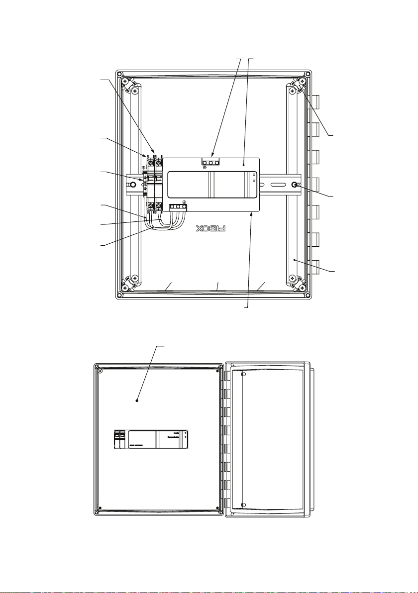
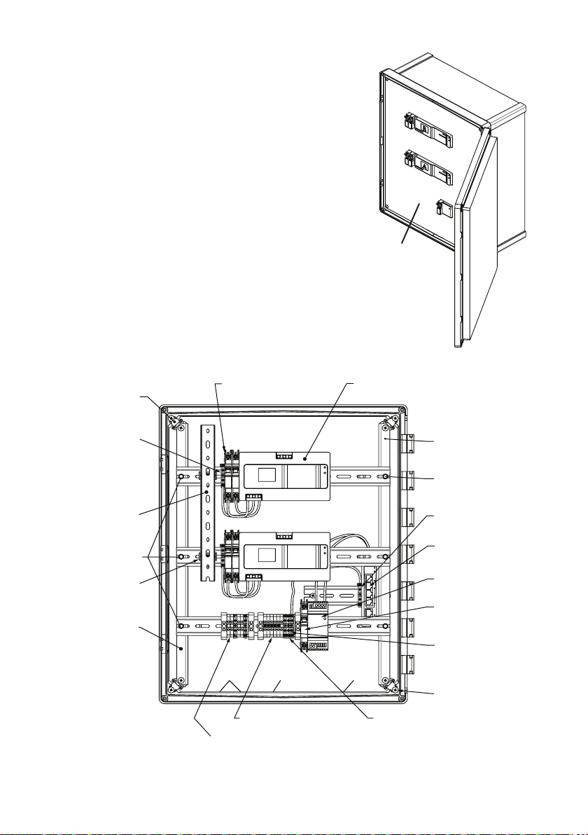
Figure 4:Multigate XT1E shown with touch-safe cover removed.
FRONT - DOOR OPENED
80 MIL PVC ACRYLIC ALLOY
DEAD FRONT COVER
Figure 5:Multigate XT1E shown with touch-safe door open and touch-safe cover in place.
CUSTOMER
CONNECTION
POINT GROUND
TERMINAL -TORQUE
TO 5.7 LB-IN
VARIABLE
DEPTH
CORNER
MOUNTING
KITS (x4)
CUSTOMER CONNECTION POINT
INPUT TB - TORQUE TO 5.3 LB-IN
SMA MULTIGATE
MODULE
GROUND WIRE
L1 WIRE
L2 WIRE
MOUNTING
BRACKETS (x2)
MULTIGATE OUTPUT
CIRCUIT BREAKER
2-POLE 15A
CUSTOMER
CONNECTION
POINT
OUTPUT TB
TORQUE TO
22 LB-IN
CUSTOMER CONNECTION
POINT - SPEEDNET (ETHERNET)
DIN RAIL TO
MOUNTING
BRACKETS
MOUNTING
POINTS (x2)
Inverter
SUNNY MULTIGATE
Communication
Inverter
Grid
L1 L2
L1 L2
INPUT
POWER
CONDUIT
OUTPUT
POWER
CONDUIT
OUTPUT
DATA
CONDUIT
FRONT VIEW - DEAD FRONT COVER REMOVED
SPEEDWIRE (ETHERNET)

Installation Manual - TEAL PN 1060147 rev 2.516
TEAL Electronics SMA America, LLC
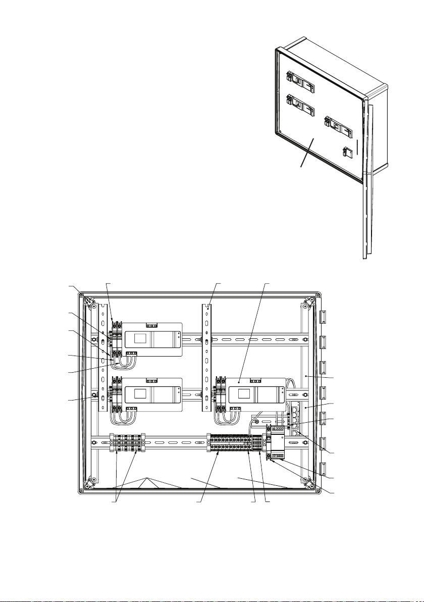
Figure 6:Multigate XT2E.
Figure 7:Multigate XT2E shown with touch-safe cover removed.
Model XT2E:
For systems with up to 24 Sunny Boy 240-US
micro inverters (2 strings of up to 12), han-
dling up to 5760W of AC power at 240VAC.
Contains 2 Sunny Multigates, each with a
2-pole 15A output circuit breaker.
Input connections are to the input terminal
blocks.
Output connections are to the output terminal
blocks.
RJ-45 Ethernet connection is to the 2 Ethernet
couplers to connect the SMA Speedwire/Web-
connect system.
Multigate XT2E Shown
with Door Open and
Touch Safe Cover
in place
BRACKET TO CORNER KIT
MOUNTING (x4)
OUTPUT CIRCUIT BREAKER
2-POLE 15A CB (x4)
SMA MULTIGATE
MODULE (x2)
MOUNTING RAIL
RECESSED DIN
RAIL FOR COUPLERS
TORQUE TO 5.7 LB-IN
OUTPUT TB CUSTOMER
CONNECTION POINTS
RJ-45 COUPLERS (x2)
FOR CONNECTION
TO SMA SPEEDNET
DEVICES (ETHERNET)
CUSTOMER
CONNECTION POINTS
DIN RAIL TO
MOUNTING BRACKET
MOUNTING POINTS (x6)
DEAD FRONT TO
CORNER KIT
MOUNTING (x4)
MOUNTING
RAIL
MULTIGATE OUTPUT
GROUND TERMINAL (x2)
VARIABLE DEPTH
CORNER MOUNTING
KITS (x4)
TORQUE TO 5.7 LB-IN
INPUT TB CUSTOMER
CONNECTION POINTS
Inverter
Inverter
Communication
SUNNY MULTIGATE
Grid
L1 L2 G
L1 L2 G
Inverter
Inverter
Communication
SUNNY MULTIGATE
Grid
L1 L2 G
L1 L2 G
A
B
INPUT
POWER
CONDUITS
OUTPUT
POWER
CONDUIT
OUTPUT
DATA
CONDUIT
CABLE DUCT
CLIP (x2)
CABLE DUCT
DIN RAIL MOUNTING
BRACKETS (x2)
DIN RAIL MOUNTING
BRACKETS ELEVATED
4.9" FROM BACK
OF ENCLOSURE
RECESSED DIN RAIL
GROUND TERMINAL
GROUND TERMINAL
TO RECESSED RAIL - TORQUE
TO 5.7 LB-IN -
CUSTOMER CONNECTION
POINT
FRONT VIEW - DEAD FRONT COVER REMOVED
SPEEDWIRE
(x2)
Installation Manual - TEAL PN 1060147 rev 2.5 17
TEAL Electronics SMA America, LLC
Figure 9:Multigate XT2S shown with touch-safe cover removed.
Figure 8:Multigate XT2S.
CUSTOMER CONNECTION POINT
SMA MULTIGATE
MODULES (x4)
OUTPUT CIRCUIT BREAKER
2-POLE 15A CB (x4)
CABLE DUCT
CLIP (x2)
MULTIGATE OUTPUT
GROUND TERMINAL
(X2)
VARIABLE DEPTH
CORNER MOUNT
KIT (x4)
CABLE DUCT
INPUT TERMINAL BLOCKS
TORQUE TO 5.7 LB-IN
OUTPUT TERMINAL BLOCKS
TORQUE TO 5.7 LB-IN
CUSTOMER CONNECTION POINT
CUSTOMER
GROUND
LANDING
5-PORT ETHERNET SWITCH
MOUNTED ON RECESSED
DIN RAIL - CUSTOMER
CONNECTION POINT
24V DC POWER SUPPLY
FOR ETHERNET SWITCH
DIN RAIL MOUNTING
BRACKETS (x2)
POWER SUPPLY
INPUT CIRCUIT BREAKER
1-POLE 10A CB
RECESSED DIN RAIL
GROUND TERMINAL
DIN RAIL MOUNTING
BRACKETS ELEVATED
4.9" FROM BACK
OF ENCLOSURE
GROUND TERMINAL
TO RECESSED RAIL - TORQUE
TO 5.7 LB-IN -
CUSTOMER CONNECTION
POINT
Inverter
Inverter
Communication
SUNNY MULTIGATE
Grid
L1 L2 G
L1 L2 G
Inverter
Inverter
Communication
SUNNY MULTIGATE
Grid
L1 L2 G
L1 L2 G
A
B
INPUT
POWER
CONDUITS
OUTPUT
POWER
CONDUIT
OUTPUT
DATA
CONDUIT
DIN RAIL TO
MOUNTING BRACKET
MOUNTING POINTS (x6)
DEAD FRONT TO
CORNER KIT
MOUNTING (x4)
MOUNTING
RAIL
Model XT2S:
For systems with up to 24 Sunny Boy 240-US
micro inverters (2 strings of up to 12), han-
dling up to 5760W of AC power at 240VAC.
Contains 2 Sunny Multigates, each with a
2-pole 15A output circuit breaker.
Input connections are to the input terminal
blocks.
Output connections are to the output terminal
blocks.
RJ-45 Ethernet connection is to a 5 port Eth-
ernet Switch to connect the SMA Speedwire/
Webconnect system, with a 15W power sup-
ply for the switch.
Multigate XT2S Shown
with Door Open and
Touch Safe Cover
in place
(x2)
(x2)
Installation Manual - TEAL PN 1060147 rev 2.518
TEAL Electronics SMA America, LLC
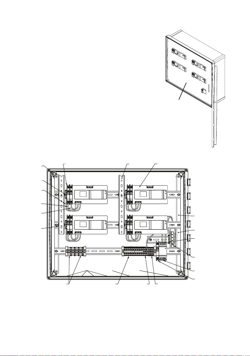
Figure 11:Multigate XT3S shown with touch-safe cover removed.
Figure 10:Multigate XT3S.
Model XT3S:
For systems with up to 36 Sunny Boy 240-US
micro inverters (3 strings of up to 12), han-
dling up to 8640W of AC power at 240VAC.
Contains 3 Sunny Multigates, each with a
2-pole 15A output circuit breaker.
Input connections are to the input terminal
blocks.
Output connections are to the output terminal
blocks.
RJ-45 Ethernet connection is to a 5 port Eth-
ernet Switch to connect the SMA Speedwire/
Webconnect system, with a 15W power sup-
ply for the switch.
Multigate XT3S Shown
with Door Open and
Touch Safe Cover
in place
CABLE DUCT
CLIP (x4)
DIN RAIL
GROUND
TERMINAL
GROUND TERMINAL TO
RECESSED RAIL - TORQUE
TO 5.7 LB-IN
5-PORT ETHERNET SWITCH
MOUNTED ON RECESSED
DIN RAIL - CUSTOMER
CONNECTION POINT
24V DC POWER SUPPLY
FOR ETHERNET SWITCH
DIN RAIL MOUNTING
BRACKETS (x2)
POWER SUPPLY
INPUT CIRCUIT BREAKER
1-POLE 10A CB
SMA MULTIGATE
MODULES (x3)
RECESSED DIN RAIL
GROUND TERMINAL
DIN RAIL MOUNTING
BRACKETS ELEVATED
4.9" FROM BACK
OF ENCLOSURE
GROUND
WIRE (x4)
INPUT TERMINAL BLOCKS
TORQUE TO 5.7 LB-IN
CUSTOMER CONNECTION POINT
OUTPUT TERMINAL BLOCKS
TORQUE TO 11.5 LB-IN
CUSTOMER CONNECTION POINT
L1 WIRE (x3)
L2 WIRE (x3)
VARIABLE
DEPTH
CORNER
MOUNTING
KIT (x4)
CUSTOMER
GROUND
LANDING
OUTPUT CIRCUIT BREAKER
2-POLE 15A CB (x3) CABLE DUCT (x2)
Inverter
Inverter
Communication
SUNNY MULTIGATE
Grid
L1 L2 G
L1 L2 G
B
Inverter
Inverter
Communication
SUNNY MULTIGATE
Grid
L1 L2 G
L1 L2 G
A
Inverter
Inverter
Communication
SUNNY MULTIGATE
Grid
L1 L2 G
L1 L2 G
C
INPUT
POWER
CONDUITS
OUTPUT
POWER
CONDUIT
OUTPUT
DATA
CONDUIT
Installation Manual - TEAL PN 1060147 rev 2.5 19
TEAL Electronics SMA America, LLC
Figure 13:Multigate XT4S shown with touch-safe cover removed.
Figure 12:Multigate XT4S.
Model XT4S:
For systems with up to 48 Sunny Boy 240-
US micro inverters (4 strings of up to 12),
handling up to 11520W of AC power at
240VAC.
Contains 4 Sunny Multigates, each with a
2-pole 15A output circuit breaker.
Input connections are to the input terminal
blocks.
Output connections are to the output terminal
blocks.
RJ-45 Ethernet connection is to a 5 port Eth-
ernet Switch to connect the SMA Speedwire/
Webconnect system, with a 15W power sup-
ply for the switch.
Multigate XT4S Shown
with Door Open and
Touch Safe Cover
in place
CABLE DUCT
CLIP (x4)
DIN RAIL
GROUND
TERMINAL
GROUND TERMINAL TO
RECESSED RAIL - TORQUE
TO 5.7 LB-IN
5-PORT ETHERNET SWITCH
MOUNTED ON RECESSED
DIN RAIL - CUSTOMER
CONNECTION POINT
24V DC POWER SUPPLY
FOR ETHERNET SWITCH
DIN RAIL MOUNTING
BRACKETS (x2)
POWER SUPPLY
INPUT CIRCUIT BREAKER
1-POLE 10A CB
SMA MULTIGATE
MODULES (x4)
RECESSED DIN RAIL
GROUND TERMINAL
DIN RAIL MOUNTING
BRACKETS ELEVATED
4.9" FROM BACK
OF ENCLOSURE
GROUND
WIRE (x4)
INPUT TERMINAL BLOCKS
TORQUE TO 5.7 LB-IN
CUSTOMER CONNECTION POINT
OUTPUT TERMINAL BLOCKS
TORQUE TO 11.5 LB-IN
CUSTOMER CONNECTION POINT
L1 WIRE (x4)
L2 WIRE (x4)
VARIABLE
DEPTH
CORNER
MOUNTING
KIT (x4)
CUSTOMER
GROUND
LANDING
OUTPUT CIRCUIT BREAKER
2-POLE 15A CB (x4) CABLE DUCT (x2)
Inverter
Inverter
Communication
SUNNY MULTIGATE
Grid
L1 L2 G
L1 L2 G
B
Inverter
Inverter
Communication
SUNNY MULTIGATE
Grid
L1 L2 G
L1 L2 G
A
Inverter
Inverter
Communication
SUNNY MULTIGATE
Grid
L1 L2 G
L1 L2 G
C
Inverter
Inverter
Communication
SUNNY MULTIGATE
Grid
L1 L2 G
L1 L2 G
D
INPUT
POWER
CONDUITS
OUTPUT
POWER
CONDUIT
OUTPUT
DATA
CONDUIT
Installation Manual - TEAL PN 1060147 rev 2.520
TEAL Electronics SMA America, LLC
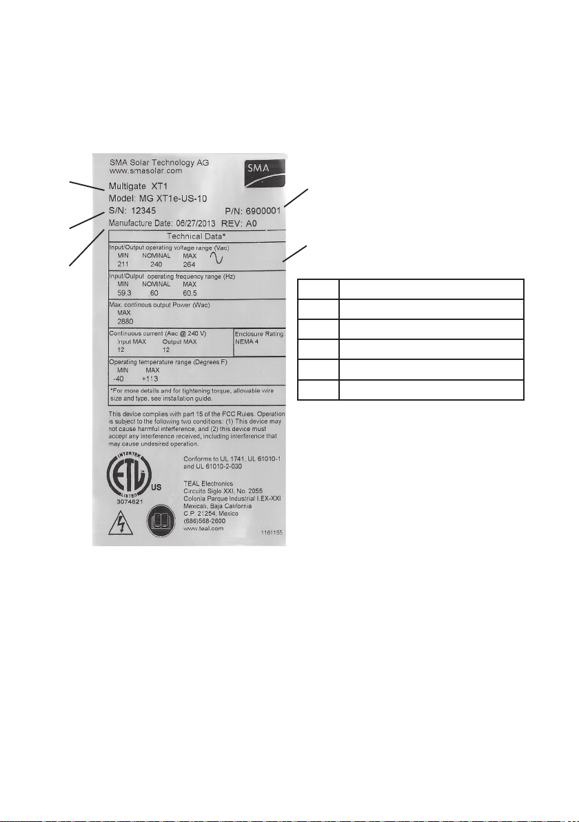
4.3 Type Labels and Stickers
Multigate XT
The type label provides a unique identification of the Multigate XT. The product specific
data type label is located on the left-hand side of the enclosure, opposite to the hinge.
The information on the type label is required for
both safe operation of the Multigate XT and for
customer support from the SMA Service Line.
The type label must be permanently affixed to
the Multigate XT.
Item Description
A Product Name and Model Code
B Multigate XT Part Number
C Multigate XT Serial Number
D Multigate XT Date of Manufacture
E Device Specic Characteristics
Figure 14: Example of the Multigate XT Type Label.
A
C
B
E
D
Table of contents


