Opitec Grand Prix Racing User manual

ø 2
ø 3
ø 4
ø 15
Superglue
101.532
Grand Prix Racing
Tools Required:
Philips
Screwdriver
Round File
Please Note!
The OPITEC handicraft packs are not toys in a typical off-the-shelf sense, but rather additional teaching and lear-
ning material for educational purposes. This craft pack may only be constructed by children and adolescents under
the guidance and supervision of experienced adults. Not suitable for children under 36 months. Choking hazard!
Jigsaworscroll
saw(metalsaw
blade)
Pricking Awl
Drill
Pencil
RulerEngineer's File
Machine Vice Wrench
Slot
Screw-
Driver
Scissors
Clear Adhesive
Tape
Hacksaw
Side CuttersSoldering Iron
with Plummet
Bending Aid

2
Instruction 101.658
Grand Prix Racing
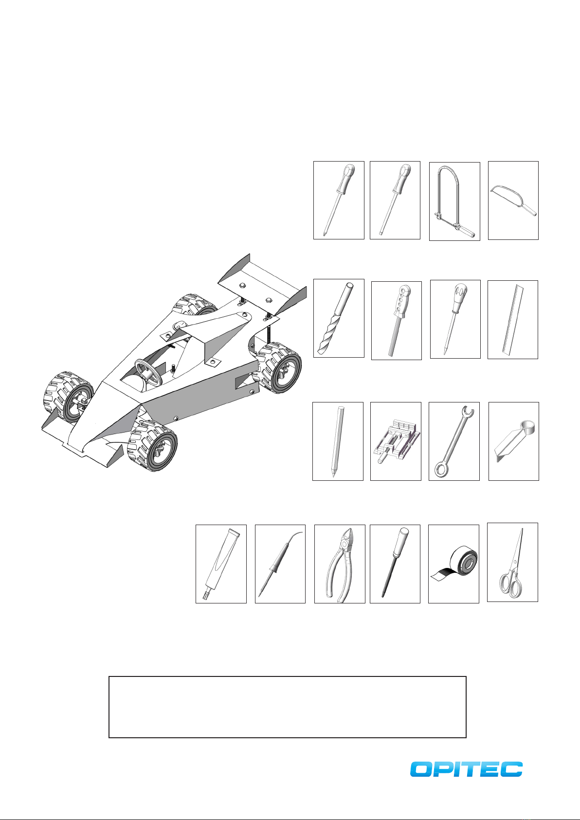
Parts List Number of pieces Size (mm): Description Part no.
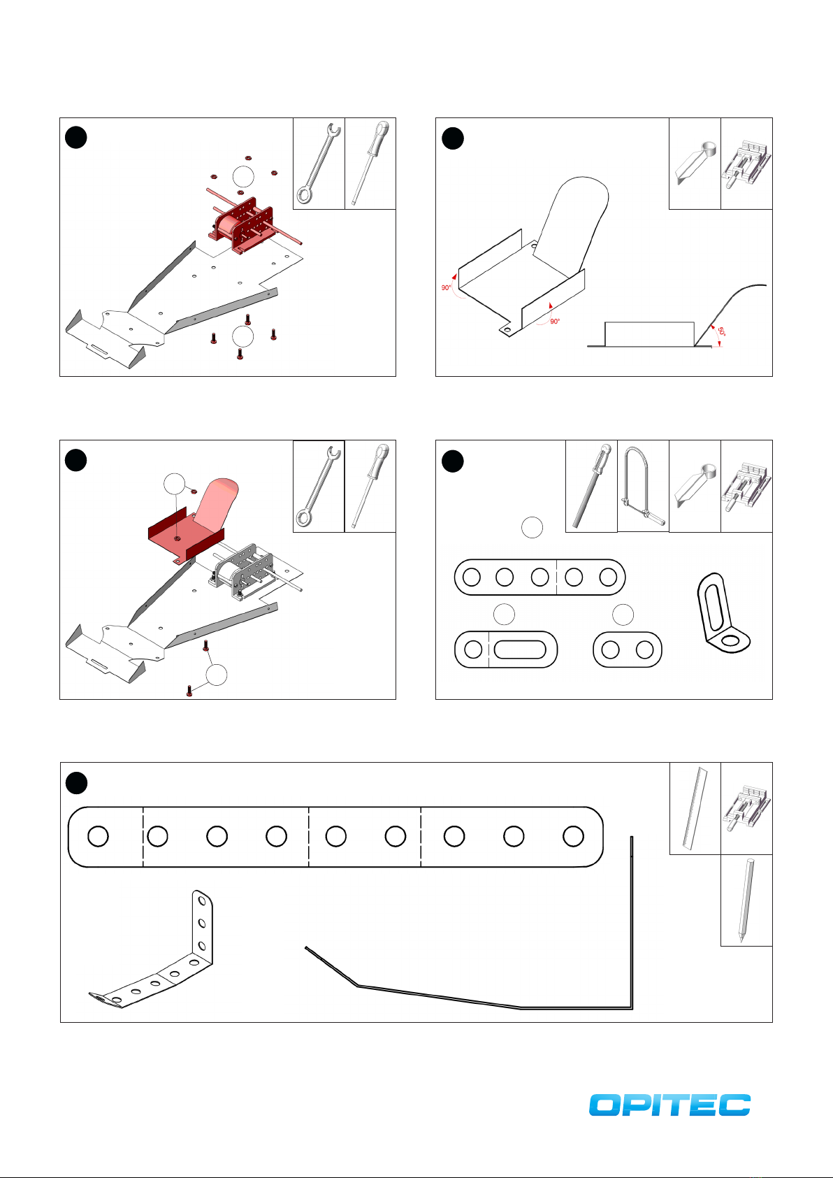
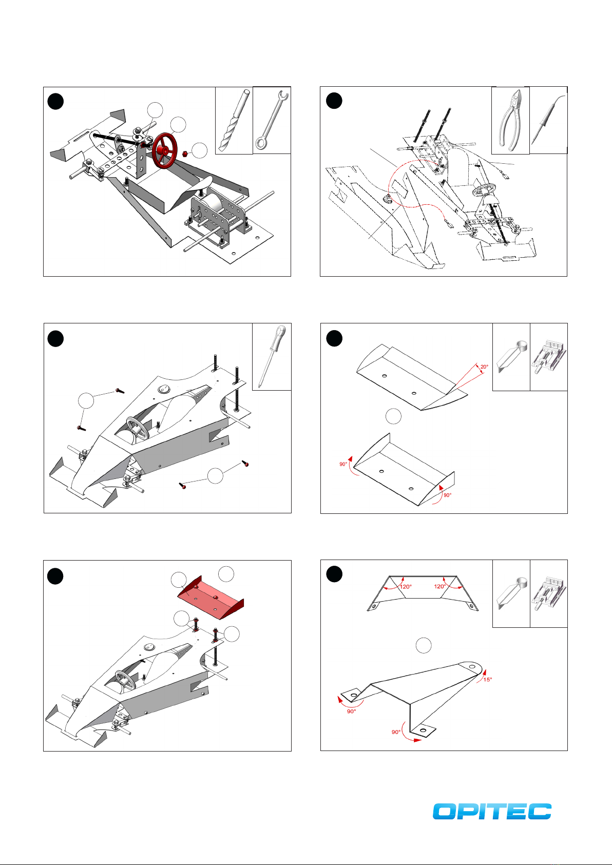
Tin Sheet 1 320x220x0,5 Vehicle Shell 1
Tin Sheet 1 300x160x0,5 Vehicle Base 2
Tin Sheet 1 120x100x0,5 Cover 3
Tin Sheet 1 150x90x0,5 Seat 4
Tin Sheet 1 120x50x0,5 Rear Spoiler 5
Flat Bar, 9 Holes 1 130x15 Tie Rod 6
Flat Bar (5-hole) 1 Steering Shaft 7
Rocker Switch round 1 ø 16.3 Switch 8
Metal Shaft 1 150x3 Axis 9
Blade receptacle 2 Battery Connection 10
Engine R 140 1 Motor 11
Threaded Rod 1 100x4 Handlebars 12
Metal Shaft 1 70x3 Axle Gear 13
Spacer Wheels 2 Attaching wheels 14
Phillips screw 12 Screw Connection 15
Cylinder Head Screw 2 35x3 Screw Connection 16
Cylinder Head Screw 2 70x4 Screw Connection 17
Cylinder Head Screw 15 10x4 Screw Connection 18
Cylinder Head Screw 2 25x4 Screw Connection 19
Nut 2 M3 Screw Connection 20
Nut 30 M4 Screw Connection 21
Head nut 6 M4 Screw Connection 22
Washer 49/4,3 Screw Connection 23
Double Gears 2 50/10 Transmission 24
Pinion 11,9 Motor Axis 25
Mounting bracket geared motor 1 Gear Motor 26
Distance Pieces 1 Gear Motor 27
Spacer 27/3,6 Gear Motor 28
Reducer 2 Attaching wheels 29
Steering wheel 1ø 37 Steering Wheel 30
Perforated Plate 1 135x15x1 Attachment front axle 31
Jumper Wire 1 500 Cabling 32
Wheels, Tyres and Rims 4ø 52 Bikes 33

3
1
1
3
5 6
ø 4
2
2
ø 3
ø 2
2
ø 4
ø 3
Drill through holes (ø 3.4) and then saw out the upper part with a saw
blade with metal saw blade. File the saw edges with the workshop file.
4
4
Cut out the template for the lower part (page 11 + 13) and stick it to the
tinplate (2) with adhesive tape. Mark the position of the holes with
the piercer.
Cut out the template for the seat (page 13) and stick it to the tin sheet
(4) with adhesive tape. Mark the position of the holes with the piercer.
Drill through holes (ø 4) and then saw out the seat with the metal saw
blade jigsaw. File the saw edges with the workshop file.
Instruction 101.658
Grand Prix Racing
Cut out the template for the upper part (page 15 + 17), stick it together
and stick it to the tinplate (2) with adhesive tape. Mark the position of
the holes with the piercer.
Drill through holes (ø 2.3) and then saw out the upper part with the
saw blade with metal saw blade. File the saw edges with the work-
shop file or round file.

7 8
ø 4
910
ø 4
11
Instruction 101.658
Grand Prix Racing
Cut out the template for the rear spoiler (page 17) and stick it to the tin
sheet (5) with adhesive tape. Mark the position of the holes with the
piercer.
Drill through holes (ø 4) and then saw out the seat with the metal saw
blade jigsaw. File the saw edges with the workshop file.
Cut out the template for the construction (page.13) and stick it to the
tin sheet (3) with adhesive tape. Mark the position of the holes with
the piercer.
Drill holes (ø 3) and then saw out the structure with a metal saw blade
jigsaw. File the saw edges with the workshop file.
Bend the lower part (2) at the lateral bending edges 90 ° upwards as illustrated. Then bend the horizontal bending edges as shown in the side view.
Side View

12
13 14
Assemble the mounting brackets (26), the motor (11), the spacer
wheels and screw them together with the screws (16) and the nuts
(20). See picture!
26
28
16
11
20
15 16
Place the motor pinion (25) on the motor axle as shown. Place a nut
(21) and a gear (24) on the axle (13). Install the second gear on the axle
(9) as shown.
Insert and center the two shafts (13 + 9) through the holes provided in
the mounting brackets as shown.
9
13 24
25 21
Instruction 101.658
Grand Prix Racing
Bend the upper part (2) at the lateral bending edges as shown 90 ° downwards. Then bend 20 ° downwards as shown in the side view of the horizon-
tal bending edge. Round the front piece.
Side View
Insert the switch (8) into the provided hole (ø 15) and secure with
super glue if necessary.

17 18
Bend the seat (4) at the bending edges as shown. To do this, bend the
side armrests 90 ° upwards and bend the backrest 50 ° upwards.
Secure the finished gearmotor to the intended position on the base
using the screws (18) and nuts (21) as shown.
18
21
19 20
Cut o the flat bar (7) at the dotted line and at both parts round o
the sawing edges with the file as shown. Saw out a long hole on the
3-hole strip from 2 holes. Then turn part 7a as shown.
Secure the seat to the intended position on the base with the screws
(18) and nuts (21) as shown.
18
21
7
7a 7b
21
Mark the dashed lines as bending edges on the perforated plate (31). Bend according to the bending template (see illustration).
Bending Template M 1:! 1
Instruction 101.658
Grand Prix Racing

22 23
Connect the bent steering finger mount (7a) to the steering finger (7b)
with a screw (18) and two nuts (21) as shown. Counter nuts for fixing.
Then connect to the tie rod (6) with a screw (18) and a nut (21).
Position the curved perforated sheet metal strip with two screws (18)
and two nuts (21) in the intended position as shown.
18
21
7a
7b
18
21
6
24 25
Fasten the finished front axle on both sides to the lower part with one
screw (19), two nuts (21) and a cap nut (22). Lock upper cap nut and
nut.
Tighten the two stub axles with one screw (18) and two nuts (21) at
both ends of the tie rod. Counter nuts.
14
14
21
21
18
18
2x
2x
19
21
21
22
26 27
Align and fix the handlebar (12) by fastening the two nuts (21). Fasten
head-on with a cap nut (22).
Screw a nut (21) onto the handlebar (12). Guide the other end of the
handlebar through the steering finger (7b). Then at this end, also
unscrew a nut. Then thread the ends of the handlebar into the holes
in the perforated plate (31).
7b
21
12
31
22
21
12
Instruction 101.658
Grand Prix Racing

28 29
Cut o three pieces of approx. 100mm from the jumper wire (32) and
connect as described in the drawing. Connect a blade receptacle (10)
to each end of the cable.
Drill the bore of the steering wheel (30) with the drill (ø4). Then screw
on a nut (21) on the handlebar and put on the Lankrad. Secure with a
cap nut (22).
30
22 ø4
21
Connect the cable to
the + pole of the motor
and to the switch
Connect the cable
to the free switch
connection
Cable on - Pole
of the motor
connect
30
Attach the upper part of the body and tighten the screws (15) as
shown in the illustration. .
15
15
32
Screw 2 nuts (21) onto the rear two screws at the rear as shown. Then
place the rear spoiler (5) and fix it with the cap nuts (22).
21
21
522
31
Turn the tail fin of the tailor-made tinplate for the rear spoiler (5) 20 °
upwards. Then bend the side flaps 90 ° upwards as well
5
Bend the upper cover (3) at the bending edges. Then bend the drilled
lugs 90 ° and bend the rear semicircular lug 15 ° upwards.
3
33
Instruction 101.658
Grand Prix Racing

34
Screw the cover (3) to the intended location with three screws (15).
15
3
35
For two wheels (33) insert a reducer (29) into the center bore of the
rim as shown.
33
29
2x
36
Attach the two wheels (33) with reducer (29) to the rear axle. Attach
the other two wheels (33) to the front axle.
Instruction 101.658
Grand Prix Racing


Instruction 101.658
Grand Prix Racing
Template lower part
M 1: 1
Cutting edge


Instruction 101.658
Grand Prix Racing
Template lower part
M 1: 1
Adhesive surface
Cutting edge
Stencil cover
M 1: 1
Template seat
M 1: 1


Instruction 101.658
Grand Prix Racing
Template shell
M 1: 1
adhesive surface
Cutting edge


adhesive surface
Cutting edge
Instruction 101.658
Grand Prix Racing
Template shell
M 1: 1
Template rear spoiler
M 1: 1
Table of contents
Other Opitec Motorized Toy Car manuals
Popular Motorized Toy Car manuals by other brands

Power Wheels
Power Wheels CDD12 owner's manual

Hocom
Hocom Audi TT RS Roadster Ride On Assembly instruction

National Products
National Products 0770 6V E-Class Mercedes-Benz owner's manual

Traxxas
Traxxas Jato 3.3 5507 owner's manual

Costway
Costway TQ10065US user manual

Mugen Seiki
Mugen Seiki MTX4R instruction manual

Peg-Perego
Peg-Perego IGED1061 6V Use and care

Carrera
Carrera EVOLUTION 25163 NIGHT RACERS Assembly and operating instructions

Jamara
Jamara BMW M4 Coupe 2,4GHz instructions

Team Losi
Team Losi Mini 8IGHT-T Operation guide

Dromida
Dromida DT4.18 BL Assembly and maintenance guide

Team Losi
Team Losi XX CR owner's manual