Teba TPW-23 User manual

Installation and User Manual
Pellet and Wood Central Heating Stoves
Model TPW-23
Tested according to DIN EN 14785
For efficiency and emission, see enclosed declaration of
conformity!
TR

Sayfa 2/ 22
TABLE OF CONTENTS
1. INTRODUCTION ...........................................................................................................................................................3
2. FEATURES.....................................................................................................................................................................3
3. WARNING .....................................................................................................................................................................3
4. INSTALLATION AND CONNECTION ...........................................................................................................................4
4.1 GENERAL INFORMATION................................................................................................................................................................. 4
4.2 SAFETY ..................................................................................................................................................................................................... 4
4.3 INSTALLATION ..................................................................................................................................................................................... 5
4.3.1 Electricity........................................................................................................................................................................................ 5
4.3.2 Sanitary............................................................................................................................................................................................ 5
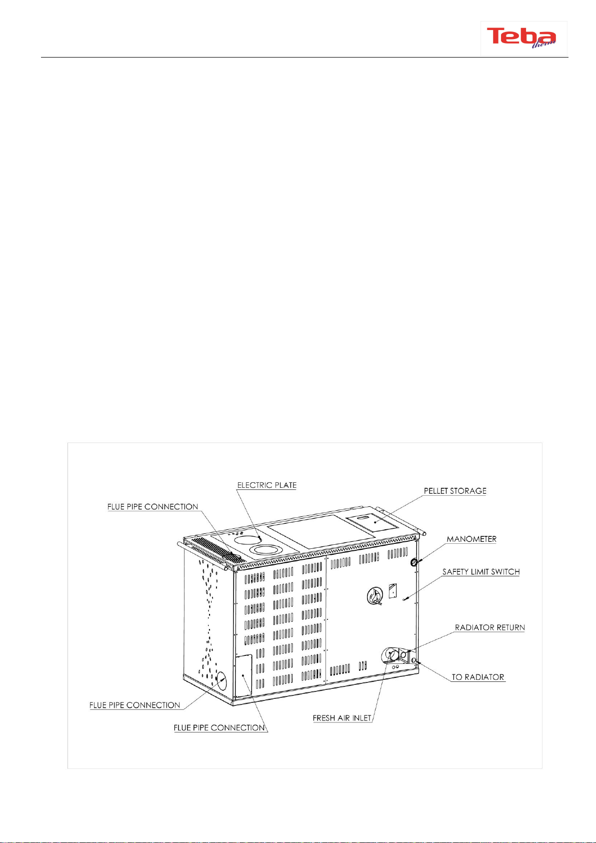
4.3.3 Flue pipe connection .................................................................................................................................................................. 6
4.3.4 Minimum Safety Distances....................................................................................................................................................... 7
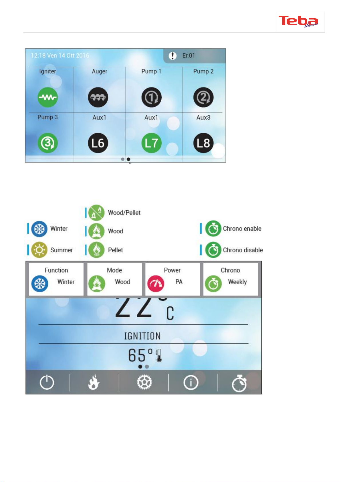
5. CONTROL PANEL .........................................................................................................................................................8
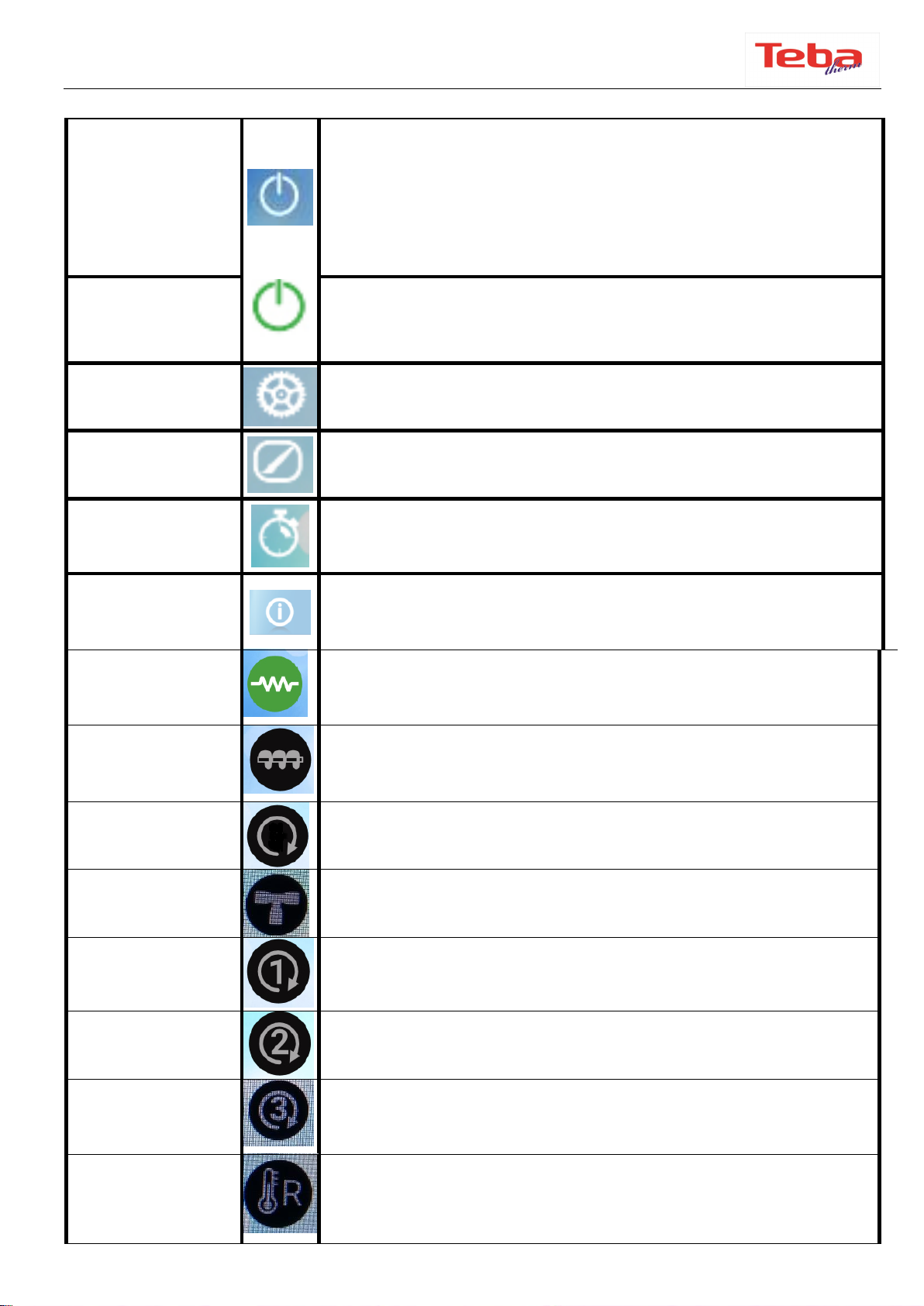
5.1 KEYS AND FUNCTIONS...................................................................................................................................................................... 8
5.2 MAIN DISPLAY AND BUTTONS ....................................................................................................................................................10
5.3 MENUS AND SYMBOLS ....................................................................................................................................................................11
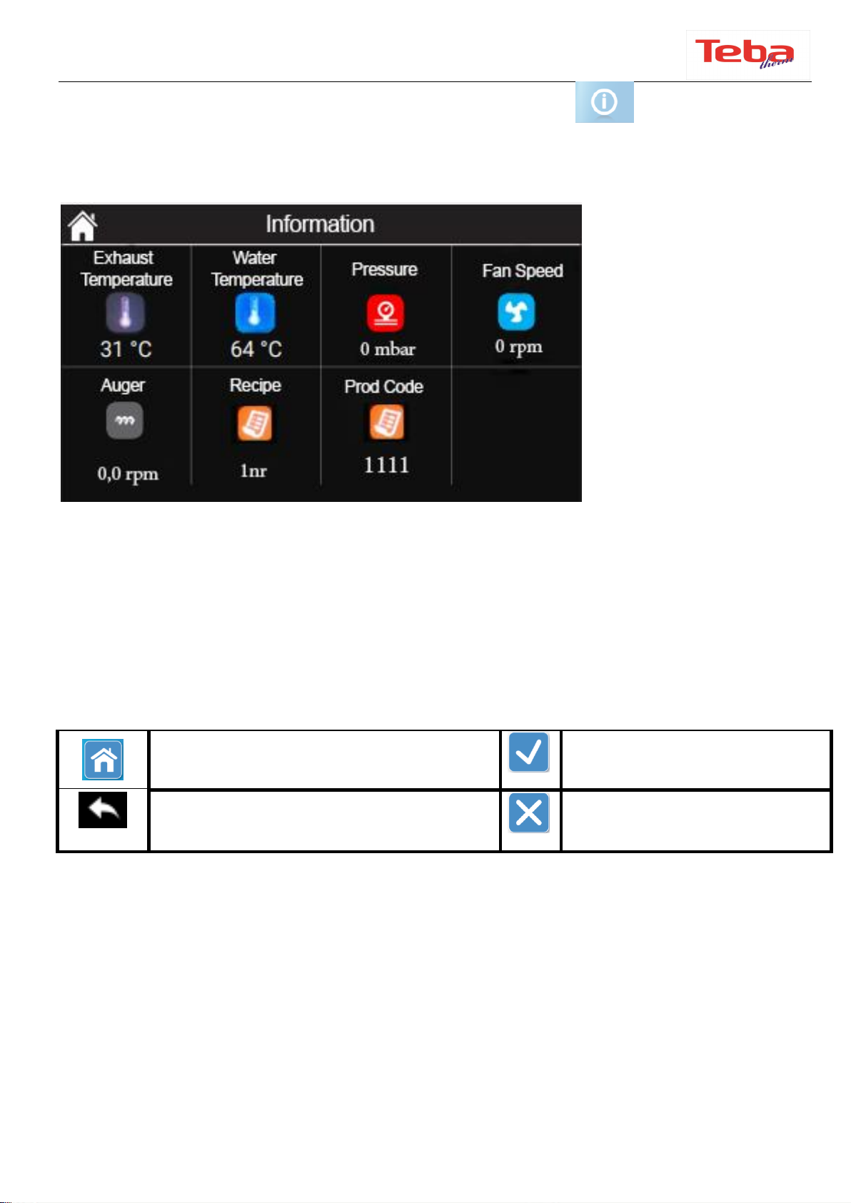
5.4 ERROR CODES AND EXPLANATIONS ........................................................................................................................................11
5.5 MENU FUNCTIONS ............................................................................................................................................................................13
5.5.2 Combustion menu .....................................................................................................................................................................13
5.5.3 Combustion management ......................................................................................................................................................14
5.5.4 Manual loading ...........................................................................................................................................................................14
5.5.5 Customization .............................................................................................................................................................................14
5.5.5 Display settings...........................................................................................................................................................................14
5.5.6 System menu ...............................................................................................................................................................................14
5.5.7 Display menu...............................................................................................................................................................................15
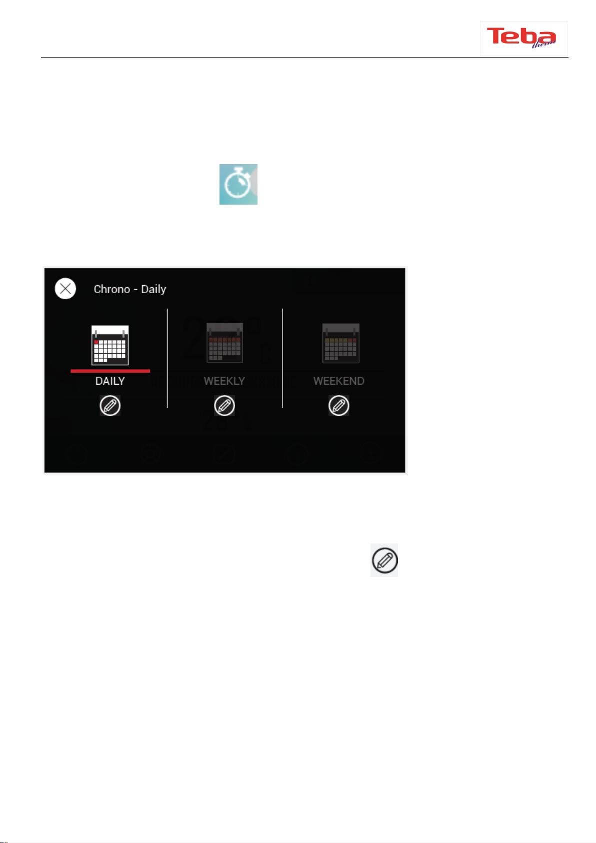
5.5.8 Chrono menu...............................................................................................................................................................................15
6. CLEANING AND MAINTNANCE.................................................................................................................................17
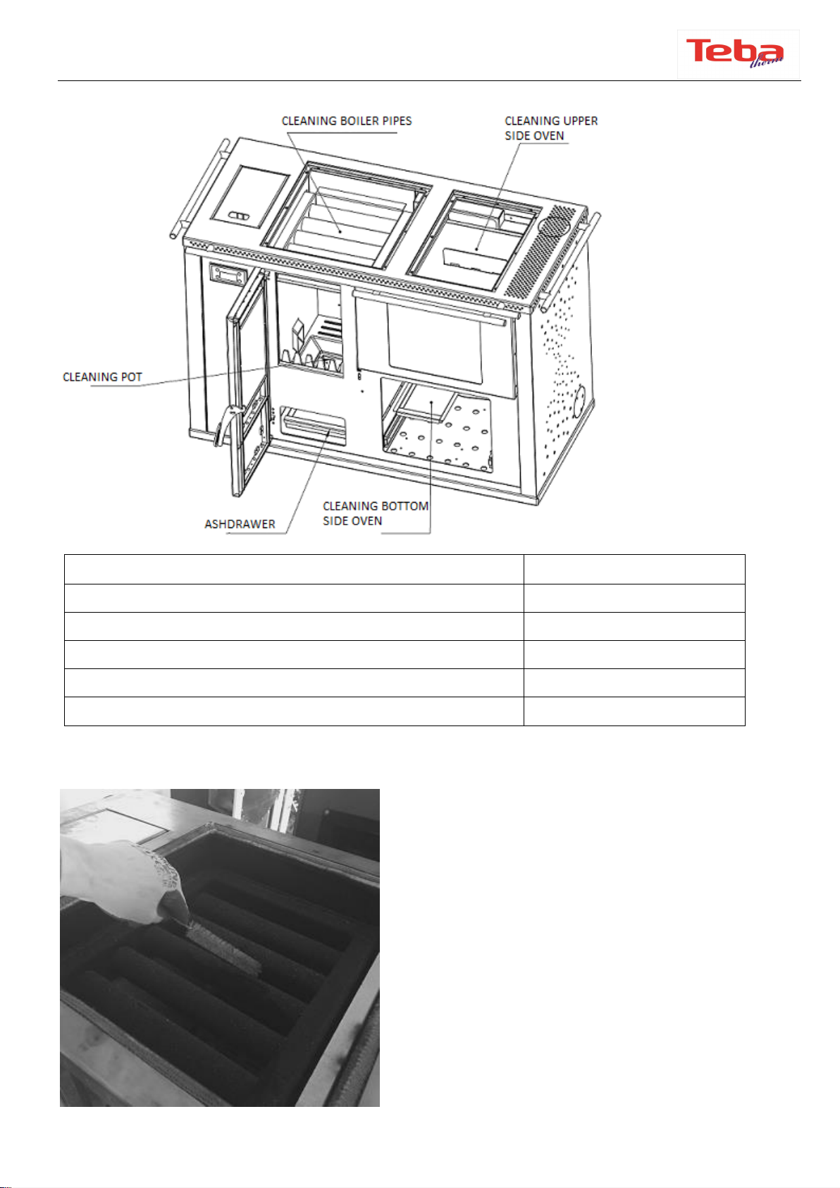
6.1 FLAME PIPES CLEANING ................................................................................................................................................................17
6.2 ASH DRAWER CLEANING ...............................................................................................................................................................18
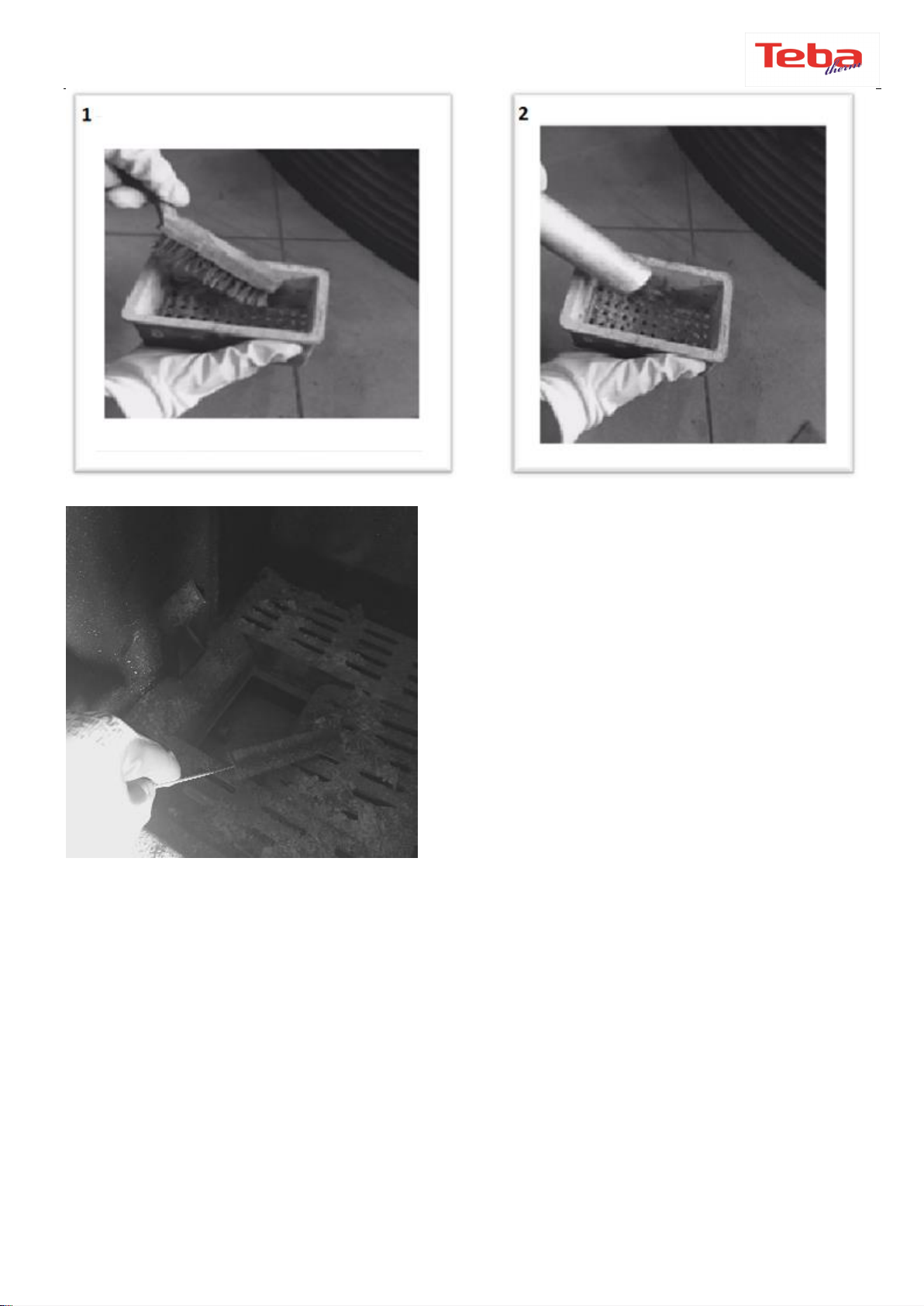
6.3 COMBUSTION POT CLEANING .....................................................................................................................................................18
6.4 OVEN CLEANING AND OVEN SECTION CLEANING .............................................................................................................19
7. GENERAL WARRANTY POLICY.................................................................................................................................22

Sayfa 3/ 22
1. INTRODUCTION
Pellet stoves and boilers are easy-to-use domestic heating appliances. They are fully
automatic and can be used inside as well as outside the house. These heating units
combines pleasure with a fireplace view. These are independent heating units that
provides heat dissipation of radiators.
You have a stove with European Standards Quality Certificate.
Please read the user manual, carefully.
It includes information on product functions and easy-to-use information.
Use of these informations increases the product quality and extend its life. You can
properly protect the fuel and the environment.
Warranty of the product depends on the right use of installation and instructions as
described in the guide.
We recommend you to keep this guide in order to reach the information about the
correct use of the stove at the beginning of every winter.
2. FEATURES
Technical Features
TPW-23
Power
25KW
Boiler connections out-in
1"- 3/4"
Hot water
1/2"
Operating pressure
1-1,5 bar
Flue pipe diameter
100 mm
Fuel capacity
20 kg pellet
8 kg wood
Efficiency
94%
Electricity
230 V-50Hz
Weight
260 kg
Boiler capacity
35lt
3. WARNING
●USE ONLY 6MM NATURAL PELLETS MANUFACTURED ACCORDING TO DIN PLUS
STANDARTS.
●DO NOT USE 8MM OR 10 MM PELET, OLIVE SEEDS, CHERRY SEEDS, HAZELNUT
SHELL ETC.

Sayfa 4/ 22
●CLEAN THE FIRE POT EVERYDAY.
●THE FLAME TRANSMISSION PIPES MUST BE CLEANED IN 3-4 DAY PERIODS WITH
THE BRUSH SUPPLIED WITH YOUR STOVE OR BOILER.
●AT THE END OF THE WINTER, GENERAL MAINTENANCE AND CLEANING (WITH
THE BRUSH) MUST BE CARIED OUT AND THE FUEL STORAGE MUST BE EMPTIED.
●DAMAGES CAUSED BY USING INAPPROPRIATE PELLET AND NON-REGULAR
CLEANING ARE NOT COVERED BY WARRANTY.
●THE FROST PROTECTION OF THE PUMPS WORKS WHEN THE HEATING WATER
DROPS BELOW + 5° C, AND TO PREVENT BLOCKING FROM CORROSION AND
SEDIMENT, THE SYSTEM AUTOMATICALLY OPERATES THE PUMP FOR 3-10 SECONDS
EVERY 24 HOURS. THEREFORE, DO NOT UNPLUG THE PRODUCTS DURING THE
WHOLE YEAR.
4. INSTALLATION AND CONNECTION
4.1 GENERAL INFORMATION
All the inspections for the pellet stove are done according to the stipulated standards. It
complies with the prescribed parameters related to combustion efficiency and flue gas
emissions. The product mentioned in this manual has been tested by the approved
bodies according to EN 14785 Standard.
The packaging of the stove protects the product from damage in the best possible way.
However, the stove or its accessories may still be damaged during transport. Therefore,
after removing the stove from the package, check whether it is complete and
undamaged. In case of any damage, notify your dealer.
4.2 SAFETY
* Product must be installed by an authorized person.
* Before installing the product, it should be determined whether the bearing capacity of
the floor to be installed is durable to the product. In case of insufficient bearing
capacity, appropriate measures should be taken. If the floor where the stove is to be
installed is flammable or heat-sensitive, you should place a base (eg marble or glass
base).
* Care must be taken to ensure that the ventitlation conditions of the place where the
product is installed and frost protection measures are taken (such as antifreeze)

Sayfa 5/ 22
* The pellet stove can operate in conjunction with the existing multiple chimneys. In
addition, the stove should not be connected at places such as the aspirator chimney and
ventilator.
* Product needs to be connected to the chimney with a shortest distance.
* Always check the water level in the stoves and radiators with the manometer before
the first installation (1 - 1.5 bar range).
* The central heating boilers and stoves cannot be used without water. Our company is
not responsible for damages caused by running without water.
* In order to get better heat efficiency and extend the life of the product, qualitative
pellet and wood fuel should be preferred. Do not use moist or wetted pellet, sawdust,
coal etc.
* Since the pellet stoves are designed according to the interior spaces and give heat to
the environment, they should not be installed in places such as bathrooms, shelter,
cellar.
4.3 INSTALLATION AND CONNECTION
* Installation must be done by an authorized person. Pellet stoves or boilers are fully
automatic products. Expansion vessel, circulation pump, thermostates, safety valve and
safety switches are readily installed inside the product. Ignition is made by a resistance
and fuel is fed by an auger.
4.3.1 Electricity
The electricity must be 230V / 50 Hz. Our company is not responsible for any damage
that may occur in case of any voltage drop or rise. We recommend taking necessary
measures as it does not include the warranty.
4.3.2 Sanitary
It is recommended that the radiator installation connection needs to be carried out by
an authorized person for regular and comfortable operation. Our company is not
responsible for any damage related to the installation.
After the safety precautions and precautions described above, the pellet stove or boiler
can be installed up to last a few radiators without using too many elbows with the
installaton line pipes 1 "- 3/4" METAL or PVC pipes. In this way, the hot water will
circulate more easily and the temperature in the radiators is felt in a short time. 1/2 "
METAL or PVC pipes can be used. The installation of the main pipes to the pellet stove
should be securely connected to the radiators by using the fittings as shown in the
diagram (Gland, nipple, valve). After the connection is done the system will be filled
with water by the authorized person. After the installation, the leakage in the

Sayfa 6/ 22
installation, radiators and valves should be checked and the air in the installation
should be emptied. This all needs to be done by the authorized person.
*According to the weather conditions of the region, it is recommended to use 1/3
portion antifreeze against corrosion and freezing.
4.3.3 Flue pipe connection
We recommend the use of a stainless steel flue pipe for the flue connection. The pellet
stove can operate in conjunction with the existing multiple chimneys. In addition, the
stove should not be connected at places such as the aspirator chimney and ventilator.
The chimney can be given directly out of the pellet stove at a short distance, or it can be
connected to the existing chimney at short distance.
ATTENTION !!!
THE PIPE AND ELBOWS USED UP TO THE CHIMNEY OUTPUT AND INPUT NEEDS
TO BE THE SAME DIAMETER. BY THE INPUT OF THE CHIMNEY A REDUCTION
MUST BE USED. MAXIMUM 4 METERS PIPES AND 2 ELBOWS NEEDS TO BE USED.
PIPE JOINTS SHOULD BE TAPED TO CONNECTOR OR ALUMINUM BAND.

Sayfa 7/ 22
4.3.4 Minimum Safety Distances
While installing the stove, the fire regulations and chimney’s instructions must be
complied. For any related questions please ask the chimney installer. Minimum
distances to be observed in flammable or heat-sensitive materials (eg furniture,
wallpaper, wood panels) (see diagram below) are:
A25cm from rear wall

Sayfa 8/ 22
B15cm from lateral wall and
C 80cm from the radiation area (front side of the product)
Flammable materials and furniture should not be placed at a distance of 80 cm in the
radiation area (C) of the flame monitoring cover.
This distance can be reduced to 40 cm when the protection panel is placed between the
stove and the materials that are likely to burn.
Minimum distances for flammable materials and furniture are indicated on the product
label and must not be exceeded. If the floor where the stove needs to be installed is
flammable or heat-sensitive, you should place the product on the ground protection
plate (eg marble or glass base).
In this case the minimum dimensions of stove bottom plate (look at drawing) should
be:
D 50cm (front length)
E 30cm (lateral length from the inner edge of the fire chamber cover)
You can order the floor protection plate from seller when you require.
5. CONTROL PANEL
5.1 KEYS AND FUNCTIONS

Sayfa 9/ 22
The screen will be accessed when swiped to the left
The active ones are displayed in green, inactive in black.
The main screen will be accessed when scrolled down
This screen is displayed in the Summer-Winter Menu, combustion management and the
level of the Pellet or wood mode is shown.

Sayfa 10 / 22
5.2 MAIN DISPLAY AND BUTTONS
ON/OFF - RESET
Pressing this symbol in the lower left corner of the screen
will display “Swipe to Open”, the system will start when you
swipe.
If there is an error in the system, touch this symbol again to
remove the error, then ”Swipe to unblock” will be displayed..
OFF
When the on/off button is pressed, this symbol appears on
the screen to swipe. This symbol becomes red when the
stove is off.
SETTINGS
Used to access the Settings Menu.
CUSTOMIZE
This menu is used to customize the Panel Settings, Display
and system menu.
CHRONO
It allows to set the start and extinguishing time of the
system at the desired time on desired days.
INFO SCREEN
When this symbol is touched, information such as flue outlet
temperature and water temperature is displayed.
IGNITION
RESISTANCE
When the symbol is green,
it indicates that the ignition resistor is active.
AUGER
This symbol indicates that the auger is active when the
symbol is green.
PUMP
This symbol indicates the pump is active when the symbol
is green
VALVE
This symbol indicates that the valve is active when the
symbol is green (not used)
V2 OUTPUT
This symbol indicates that the clappes motor is active when
the symbol is green.
AUX 2 OUTPUT
This symbol indicates that the AUX2 output is active when
the symbol is green (not used).
AUX 3 OUTPUT
This symbol indicates that the AUX3 output is active when
the symbol is green (not used).
EXTERNAL
CHRONO
When the symbol is green, it indicates that the external
chrono is active (not used).

Sayfa 11 / 22
SAMPLE VISUALS ; When you touch the info button one time following messages
will be shown on the screen;
The sample is visual, ignore the numbers.
5.3 MENUS AND SYMBOLS
Return to main menu
Save and exit menu.
Return to the previous menu
Exit menu without saving.
5.4 ERROR CODES AND EXPLANATIONS
NOTE: If you recieve an Error Code please check the related parts and the values. After
you solve the problem touch the power button for 3 seconds. If the Error Code keeps
existing, please contact your service.
In wood mode, all the Error Codes except Er04 and Er05 in locks the operation of the
boiler.

Sayfa 12 / 22
Error
Code
Explanation
Solution
Er01
Safety limit thermostat error/boiler
temperature exceeds 90°C.
Check the valves and the circulation
pump. Push the black tip of the safety
limit thermostat inside, which is on
the back side of the boiler.
Er02
Chimney emission safety switch error
Check chimney connections and
emission.
Er03
Chimney outlet temperature drop or
auger blockage error
.
Check whether the fuel is supplied by
the auger in the combustion chamber.
(If the fuel does not come, the auger
may need to be checked, please
contact the dealer)
Er04
Boiler water over temperature error
Check plumbing valves and
circulation pump.
Er05
Chimney outlet high temperature error/
flue temperature sensor error or
cleaning error
This error occurs when the
calibration values are increased or
when the general cleaning time is
reached. Please clean all the parts of
the product.
Er07
Chimney emission fan motor error
Check that your chimney is not
clogged. Reset the product by
pressing P1 button for 3 seconds, if
the error still persists, contact your
dealer.
Er08
Chimney emission fan motor encoder
error
Reset the product, contact your
dealer if the error still persists.
Er09
Low water pressure in the boiler
Check the manometer, add the
missing water.
Er10
High water pressure in the boiler
Check the manometer, reduce the
water pressure by removing the
water from the air vent valve or the
drain valve
Er11
Date and time error
Check the time and date
Er12
Ignition failed
This error can occur due to the
impurity of the resistance or pot,
check the resistance and clean the
pot.
Er15
Security Fault Low Voltage
Check the voltage waves.
Er16
RS485 communication error
Call your service.
Er18
Pellet level sensor error.
Check the pellet storage and add
pellet.
Er52
Input-Output Module Error (I2C)
Call your service.

Sayfa 13 / 22
5.5 MENU FUNCTIONS
Press the symbols on the touch screen to enter the menus. To save the changes press
button. Press button to exit from the menu.
5.5.1 Settings menu
Press button to enter the settings menu. In the settings menu, you can set the
heating power, heating management, timer and manual loading.
5.5.2 Combustion menü
OPERATION
There are 3 functions in this section; pellet mode, wood mode
and combi mode.
Pellet Mode: Only pellet fuel is used.
Wood Mode: Only wood fuel is used, fire starts manually.
Combi mode: Fire starts with pellet and then continues with
wood.
PELLET POWER
This section contains the Power (1-6 and Auto options)
options where the combustion power of the fuel is selected.
WOOD POWER
AUGER CALIBRATION
Auger menu is used for loading speed of the pellet
adjustments. You can move the screen left / right to adjust the
pellet loading speed deceleration or acceleration values in the
display (+ 5...0... -5). Press the button to save the data and
to exit . To exit without saving press the button .
FAN CALIBRATION
Menu used for flue fan speed adjustment. You can move the
screen left / right to adjust the pellet loading speed
deceleration or acceleration values in the display (+ 5...0... -5).
Press the button to save the data and to exit . To exit
without saving press the button .

Sayfa 14 / 22
5.5.3 Combustion management
Boiler Thermostat
Press the boiler thermostat to enter the sub-menu. You can move
the display to the right / left to change the boiler thermostat value
(max 75 - min 50). To save the changes touch button.
Touch button to exit menu.
Summer-Winter
Menu
Touching ‘Summer-Winter’ enables you to enter the sub-menu. If
you touch ‘Winter’ you choose the 'Winter mode' and save by
touching button. Touch button to exit menu. The summer-
mode is not used.
5.5.4 Manual loading
This menu is used to transmit the fuel from the fuel storage to the fire pot. This will be
activated by touching the symbol on the right side of the menu.
5.5.5 Customization
By touching this symbol, the screen below will exist
5.5.5 Display settings
TIME AND DATE
To set the time for daily use, you can change the time zones
and date by sliding the screen. You must confirm it with the
button.
LANGUAGE
Language options are available in this menu, tap the language
you want to use to select it.
5.5.6 System menu
ONLY FOR AUTHORIZED SERVICE

Sayfa 15 / 22
5.5.7 Display menu
This menu is used to set functions such as screen brightness, minimum brightness, and
sound.
5.5.8 Chrono menu
To enter this menu, press the on the lower right corner of the main menu. In
order to be able to set the time, first check that your time and date are correct. When
you enter the menu you will see the following screen.
Tap Daily, Weekly or Weekend to select the desired timing interval. The inactive time
range will be gray. To enter and edit the mode press symbol. When it is in Daily
mode, you can select the working day you want from Monday, Tuesday,
Wednesday...Sunday. In the weekly mode, you will see the Monday to Sunday option on
the second line covering all days of the week. In weekend mode, you'll find Monday to
Friday-(covers all days in the range) and Saturday-Sunday (which includes two days).

Sayfa 16 / 22
After selecting the time mode, this screen will appear (the text will change according to
the selected mode). We can select the working day we want by scrolling the screen.
When we touch the opening and closing hours, the screen will be displayed.
Set the desired hours from the Start and ”Stop“ section on the left with pressing
button. After the selected hours are displayed on the right side, the check box next to
the time zones is touched and activated.

Sayfa 17 / 22
6. CLEANING AND MAINTNANCE
Cleaning sections
Cleaning Frequency
Flame Pipes cleaning
Once a week
Ash drawer cleaning
Daily
Combustion pot cleaning
Daily
Oven bottom and top cleaning
Twice a year
Oven cleaning
Once a year
6.1 FLAME PIPES CLEANING
Remove the metal plate on the product's
upper table and brush the exchanger pipes
with the brush provided with the stove or
boiler. Do this once a week.

Sayfa 18 / 22
6.2 ASH DRAWER CLEANING
Ash drawer under the fire pot must be
emptied daily.
Open the oven door and empty the ash
drawer located on the upper side of the
oven.
6.3 COMBUSTION POT CLEANING
Carefully open the lid of the product so that the ashes are not spilled out, clean them
with a vacuum cleaner (see picture 2). Make sure that the electricity is turned off and
that it to stove is cold.
Clean the burner pot with the help of a wire brush (picture 1)
Make sure that the combustion pot does not accumulate in the pellet and does not affect
the ignition. Pot cleaning should be done daily.

Sayfa 19 / 22
It is advised to clean the grate daily.
6.4 OVEN CLEANING AND OVEN SECTION CLEANING
The oven section needs to be cleaned once a year. First the oven door and then the oven
section must be removed. In order to remove the cover, the hinges must be removed by
hand or by a metal part and then the cover must be closed and removed.

Sayfa 20 / 22
In order to remove the oven section after the cover, the screws and the oven section
must be removed. After the dismantling, these sections should be cleaned with a wire
brush.
Table of contents
Other Teba Stove manuals