TECALEMIT TEC 4000 Manual
4000 4-Post 4-Tonne Hoist
TEC4000
TEC4011 ‘Wheels-Free’ Beams

Page
2 - 6
6 - 7
7
8 - 9
10
11 - 22
Subject
Installation Instructions
Operating Instructions
To raise hoist
To lower hoist
Wheels-free system (where fitted)
Routine Maintenance
Monthly
Yearly
Service and Repairs
Wire rope inspection
Wire rope replacement
Cylinder removal
Hydraulic pump removal
Hydraulic hose replacement
Fault Diagnosis
Illustrated Parts Lists
Contents
Safety Precautions
1. Do not operate the hoist while people are on or near it.
2. Always check the column hooks are engaged before starting work.
3. Consider the stability of the vehicle before removing parts.
4. Always keep the tracks and lifting pads clean and free from oil or grease.
5. Do not directly spray or hose the hoist with water as it will eventually cause corrosion and shorten the
life of the hoist.
6. Always return the operating switch to the horizontal “off” position when stopping the hoist after raising
or lowering. This will immediately stop and isolate the hoist if there is any malfunction in the electrics.
7. If any accident occurs during operation, check the cables are still on their pulleys and are not damaged.
TEC4000 Statutory Design Approvals
South Australia
Western Australia
New South Wales
Northern Territory
Queensland
Tasmania
Victoria
New Zealand
CLF/DH
31/49/7
75730/C
N4036
CH13166
C1090
L87/2126/00
21.903.01
29 Nov 1988
25 Nov 1987
25 Jan 1988
04 Feb 1988
19 Feb 1988
21 Apr 1988
19 Jul 1988
25 May 1989
State Approval Reference No. Date

INSTALLATION INSTRUCTIONS
By following these instructions carefully, your new hoist
can be assembled quickly to give safe, smooth and
efficient operation and an extended, trouble-free life.
1. Select an undercover position for the hoist allowing
for direct access for vehicles (or as specific
regulations may require).
Mark out the floor plan as per FIG.A
2. Inspect the quality of the floor at the proposed site.
It must be a flat concrete floor of minimum
thickness 100mm and minimum strength grade 28
Mpa. If expanding-type masonry anchors are to be
used to hold down the columns they must not be
installed within 150 mm of any edge, crack or other
fastener in the floor and must be a minimum of
16 mm diameter (thread size). (Some authorities
may not approve expanding-type masonry anchors
- if so, 16 bolts of 16 mm diameter will need to be
concreted into the floor and allowed to cure for one
month minimum. If the floor is not satisfactory it
must be relaid or, if this is impractical, 600mm
squares must be cut through the existing floor and
new concrete bases of minimum thickness 150mm
and minimum strength grade 28 Mpa laid to provide
sound foundations for the four columns. Allow to
cure for a minimum of one month before using the
hoist.
3a.Install a mains isolator switch on a wall or column
next to where the hoist power column will be
situated. The power supply must be 415V, 3-phase
plus neutral, 50Hz. The wire (conductor) size must
2
be a minimum 7-strand, 2.5 mm cross sectional
area and copper.
3b.An air supply to the hoist is required with 5.5 to 8
bar pressure (70 to 100 Psi) and connected to a
filter and lubricator installed on a wall or column
adjacent to the hoist power column.
4. Place the tracks on trestles or other suitable
supports in accordance with the floor plan. The
power track containing the hydraulic cylinder and
cables must be on the power column side of the
plan with the hydraulic hose at the power column
end. The overhanging lips of the tracks go on the
outside of the hoist.
5. Remove the four cables and the hydraulic hose
from the power track channels. Feed the two long
cables through the ends of the slave track. Feed
the 4.33 mm long black nylon tube through the
track outer U channel that the hydraulic hose
passes through.
up the bolt holes and position the crossmember
ends to where the columns will be.
Note:The two crossmembers are different - refer
Fig. B.
7a.On Basic Hoist
Line up the bolt holes. Fit the fixed wheel stops and
drive-on ramps to the crossmember and bolt the
tracks, etc. tightly together with M10 x 20 mm long
grade 8.8 screws. Refer Fig. C. Connect the black
nylon tube in the track to the tee connectors in the
crossmembers.
FIG. A Floor Plan
600mm
approx
4346mm
200mm
200mm
225mm
205mm
2998mm
POWER
COLUMN
POWER
CROSSMEMBER
SLAVE
CROSSMEMBER
600mm
SQ.
POWER TRACK
SLAVE TRACK
4725mm
Page 2
6. Fit the two crossmembers on to the ends of the
tracks. Move the tracks and crossmembers to line
7b.On Wheels-Free Hoist
(A) Remove the column hooks, air cylinders,
springs and swivel blocks from the outside of
both crossmembers. Remove the air lines from
inside the crossmembers.
(B) Line up the holes in the tracks and
crossmembers, fit the four extension U-brackets
using the M10 x 25 mm long grade 8.8 screws
supplied with the wheels-free beam kit. Do not
tighten yet.
(C) Place the wheels-free crossmembers into the U-
brackets over the locating pins.
Note: The crossmembers are not the same. The
operating handles must be on the power column side
of the hoist.
(D) Engage the interlock pins to lock the wheels-
free crossmembers and the hoist crossmembers
together. Adjust the U-brackets so the interlock
pins engage freely. Now fully tighten the M10
screws. Remove the wheels-free crossmembers
to tighten all the screws.
(E) Fit the wheel stops and drive-on ramps to the
outside of the U-brackets with the M10 x 20mm
long screws and nuts. Refer Fig.C. Refit the
wheels-free crossmembers.
wheels-free crossmember, down into the U-
brackets so that the crossmember is not leaning
out and does not wobble.
(G) Adjust the locating screws on the top inside
edge of the wheels-free crossmembers until the
crossmember is not leaning inward. Check the
interlock pins still engage freely.
8. Carefully remove the clutches (Fig. D) and the cable
retainers from the end of the crossmembers and
feed the cables through the ends of the
crossmembers and around the cable pulleys. Refit
the cable retainers. Place a clutch spring and guide
ferrule over the guide pin on the clutch and refit the
clutch to the crossmember.
Note: The four clutches are preset for each corner and
must not be mixed up or damaged in any way.
9. Remove the clutch rods from the columns and offer
each column up to the crossmembers so that the
notches are on the outside in line with the column
hooks on the crossmembers.
Note: The power column (which has two holes in the
back) must go on the crossmember beside the
hydraulic hose.
(A) On Wheels-Free Hoist
Fit a coiled hose, bulkhead connector and
elbow connector to the column furthest from the
power column.
(B) On All Hoists
Connect the bottom of the coiled tube inside the
column(s) to the connector(s) at the end of the
crossmember(s) inside the column. Feed the
guide tube(s) down through the top of the
column(s)and through the middle of the coiled
tube(s).
10.Remove the plastic plug from the end of the
hydraulic hose and pull hard on the cables to
extend the cylinder. Now feed the cable adjusting
screws through the top of each column and fit two
nuts to each screw. Leave the nuts loose.
11.Feed the clutch rods down through the top of the
columns. Hold the clutch square against the clutch
spring stop and lower the clutch rod through
the hole in the clutch and the guide bush just below
the clutch. Now check that the spring on the clutch
is still straight and is not buckled. Screw the clutch
rod into the base of the column while still holding
the clutch square. (If the clutch is not held square,
it will mark the clutch rod and cause the guide bush
to wear rapidly.) Tighten the nut on the top of the
rod sufficiently to tension the rod.
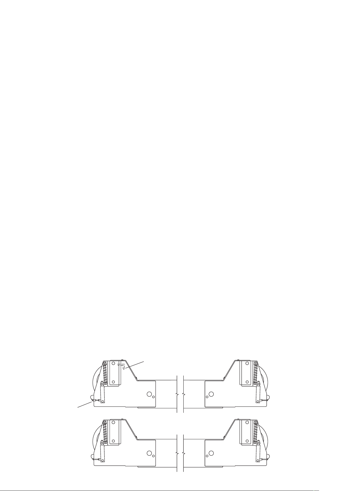
FIG. B Power Crossmember
LIMIT SWITCH TRIGGER
TEE
CONNECTOR
Slave Crossmember
(F) Adjust the screws in the bottom outer edge of the
12.Use a spirit level to establish the slope of the floor
and which column is at the highest point. The other
three columns must be packed up to exactly the
same height.
THIS REQUIREMENT IS CRITICAL FOR ACCURATE
WHEEL ALIGNMENT
Now adjust the power column by packing until it is
vertical when checked using a spirit level on the
clutch rod. Fit one hold-down bolt to the front of the
base plate on the power column only. Do up snug
tight only.
Note: The hold-down bolts must be a minimum of 16
mm diameter (thread size). If expanding-type masonry
anchors are used, they must not be installed within 150
mm of any edge or crack or other fastener and must be
a minimum of 16 mm (thread size), e.g. Ramset Trubolt
T16100 or Hilti stud anchor HSAM 16x110.
13.Fit the two rubber strips to the edges of the power
pack and mount it on the column with two M6 nuts
and spring washers. Mount the top limit switch to
the column. Check the limit switch roller lever is
sloping down at 30° and does not rub on the
column. Connect up the hydraulic hose to the
power pack. Make sure the hose hangs straight
down beside the column and across to the track
and does not rub on the side of the column. If the
hose will not hang correctly, rotate the hose fitting at
the hydraulic cylinder to remove any twist in the
hose. Pour 8 litres (two containers) of hydraulic oil
into the reservoir. Do not fill completely
.
(A) On Basic Hoist
Connect the right hand black nylon tube from
the power pack to the elbow connector on the
back of the column.
(B) On Wheels-Free Hoist
Fit a tee connector and 40 mm long tube to the
right hand black tube from the power pack. Fit
the 40 mm tube to the elbow connector on the
power column. From the other branch of the
tee run a length of tube up and across the roof to
the diagonally opposite column and fit to the elbow
at the back of the column.
(C) On Both Hoists
Connect an air line from the filter lubricator to
the left hand black nylon tube on the power
pack. Press the column hook button on the
power pack and check all four column hooks
operate. Listen for any air leaks.
14.Connect the power supply from the mains isolator
switch, adjacent to the hoist, to the terminal strip in
the control box using 7-strand copper wire of
2
2.5 mm cross sectional area. Turn the main switch
to up momentarily and check the motor direction - it
must be anti-clockwise rotation when viewed from
above. If the direction is wrong, switch off the
mains isolator and reverse two of the wires to the
control box. Switch on the isolator and recheck the
motor direction.
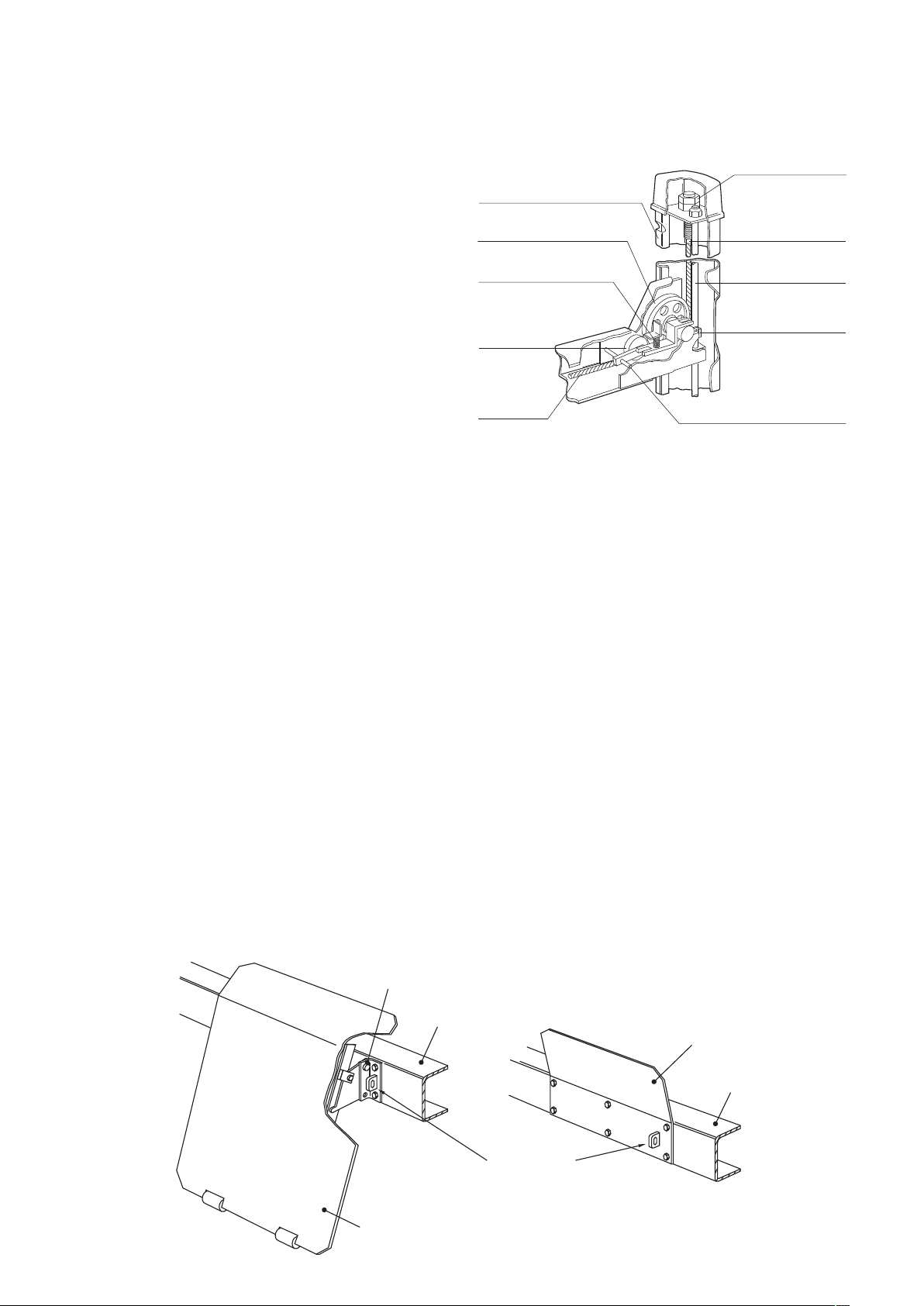
FIG. C Drive on Ramps and Wheel Stops
WHEEL STOP
CROSSMEMBER
RAMP ANGLE
CROSSMEMBER
NOTE: THIS BRACKET GOES
NEAREST THE COLUMNS
RAMP ASSEMBLY
Clutch
Actuator
Pulley
Cable Pulley
Column
Cable
Cable
Adjusting Nut
Spanner Flats
Clutch Rod
Clutch
Clutch
Actuator Pivot
FIG. D Column Safety Devices
Clutch Spring
Page 4

15.Operate the up switch and raise the hoist sufficiently
to remove the supports under the tracks (it may
take up to 20 seconds for the cylinder to fill before
the hoist will rise. Visually check the clutch actuator
pulleys are on the cables and the four clutches are
being held square to the clutch rods. Tighten the
cables if necessary.
16.Push the push button to disengage the column
hooks and turn the switch to down and allow hoist
to slowly settle to the floor. As the hoist is lowered,
the slave columns should be moved slightly as
necessary to come into alignment. If any of the
clutches engage, raise the hoist to release the
clutch and tension the cable.
17.Adjust the three slave columns by packing until they
are vertical when checked using a spirit level on
their clutch rods. Square up the four columns by
sighting across the front face of each column to the
column at the other end of the hoist. Before
installing all remaining hold-down bolts and
tightening, ensure all columns are packed to the
same height. Fit the remaining hold-down bolts and
tighten. Recheck that all columns are vertical and
square. (It is very important that the four columns
are accurately adjusted to ensure smooth, trouble-
free operation of the hoist.)
18.With the down switch held on, adjust all four cables
until the ends of the crossmembers just start to lift
off the column base plate. Lock the cable adjusting
nuts together. On wheels-free hoists, adjust the two
adjusting screws on the outside ends of the wheels-
free crossmembers so they just clear the outside
of the columns by 2-3 mm.
19.Raise the hoist about 1 metre off the floor. Check
the clutch rods are not being bowed due to
misalignment of the columns (recheck column lean
and repack if necessary). On wheels-free hoists,
check the adjusting screws on the wheels-free
crossmembers are not rubbing on the column or
have no more than 4 mm gap.
20.Drive the hoist up until the column hooks engage
in the next notch in the columns. Check that all
hooks engage in the notches at the same time
(adjust the cables if necessary). Check the hooks
all engage fully under spring pressure and
disengage freely under air pressure. With the
hooks engaged, lower hoist until the hooks are
supporting the tracks and check the tracks are level
using a spirit level (if not, repack the columns as
per step 18).
22.Lower and raise the hoist several times to expel any
23.Apply a liberal coating of SAE 140 oil to the clutch
rods and to the cables over their entire lengths
(raise and lower the hoist to get full coverage).
Apply some oil to the clutch actuator pulley axle and
pivot, the ramp rollers and pivots, the column hook
pivots and the wheels-free interlock pins.
2
24.Bolt the four Inner Toeguards (20 mm tubes) under
the tracks with the M6 x 35 mm long screws and the
thick flat washers. Also attach the hydraulic hose to
the outer screw, using the bracket on the hose.
25.Position the two outer toeguards at each end of the
hoist. Fit four bushes to the toeguards. Fit M6 x 20
mm long screws to the slotted brackets on the
wheel stops, with a thick flat washer on each side.
Screw the bush onto the screw. Leave loose.
Repeat at the other end.
26.Lower the hoist to the floor. Fit the covers to the
crossmembers and columns. Adjust the outer
toeguard pivots until they are flat on the floor, then
tighten them. On wheels-free hoists, bend the ends
of the outer toeguards towards the column base
plates until there is 80 mm gap, (this is to prevent
eye damage when the hoist is raised). Place the
wheels-free support beams together on the hoist
between the tracks.
27.Drive the heaviest available vehicle (4 tonne
maximum) on to the hoist. Raise the hoist to full
height.
28.Engage the interlock pins on wheels-free hoists.
Check all column hooks are fully engaged at the
same height. If the heights vary greatly, adjust the
cables to correct. Lower the hoist so all the weight
is on the hooks. Check hooks for proper
engagement. On wheels-free hoists check for any
tilting of the wheels-free crossmembers under load.
If tilting occurs, raise the hoist to unload the hooks
then adjust the locating screws on the top inner
edge of the wheels-free crossmember to take up
excess clearance. Retest for tilting.
29.On wheels-free hoists:
Locate the support beams under suitable pickup
points approved by the vehicle manufacturer.
Position the adaptor pads and extensions as
required.
Raise the hoist slightly to unload the interlock pins,
and disengage the pins.
21.Raise the hoist higher. If the hoist slows down and
gets noisy, add 1 litre of oil, then continue raising.
Add more oil as required until the hoist reaches
full height. Check that the top limit switch is
operated by the crossmember trip arm. On a
wheels-free hoist, check the adjusting bolts on the
outside ends of the wheels-free crossmembers
are not rubbing on the column or have no more
than 4 mm gap.
air trapped in the hydraulic system. Fully lower the
hoist, check oil level and top up if necessary.

Lower the hoist platform until the vehicle is fully
supported by the wheels-free beams. Check safety
at all pickup points and column hooks.
30.Raise the hoist to unload the column hooks.
Remove the adaptor pads, etc. Check the floor
area beneath hoist is clear of people and
obstructions. Disengage the hooks and lower the
hoist to the floor. Remove the vehicle.
The hoist is now ready for operation
OPERATING INSTRUCTIONS
To raise hoist
1. Park the vehicle centrally on the hoist. Stop the
engine and apply the parking brake.
2. Place chocks in front of and behind the wheels.
Manual chocks should be used on at least one
wheel.
3. Check the hoist area is clear of people and
obstructions, then raise hoist to desired height for
working on the vehicle.
4. On the wheels-free hoists, engage the
crossmember interlock pins.
5. Lower the hoist on to the column hooks and check
engagement of hooks visually. Turn the main switch
to the horizontal “Off” position before commencing
work.
To lower hoist
1. Check the floor area beneath the hoist is clear of
people and obstructions.
2. Raise the hoist until the column hooks are free.
3. Disengage the column hooks and lower hoist to the
floor.
4. Remove the wheel chocks, check the driveway is
clear, then drive the vehicle off the hoist.
Page 6

Wheels-free system (where fitted)
1. Park the vehicle centrally on the hoist. Stop the
engine and apply the parking brake.
2. Check the hoist area is clear of people and
obstructions, then raise hoist to desired height.
Turn the main switch to the horizontal “Off” position.
3. Position the longitudinal support beams under the
pickup points approved by the vehicle
manufacturer.
4. Position the adaptor pads under the pickup points
(adjust the beams if necessary). Use extension
pads if required.
5. Disengage the interlock pins on both ends of hoist.
Check disengagement visually.
6. Slowly lower the hoist and verify by checking
visually that all four column hooks are engaged fully
in the column notches.
Caution: It is vital that full engagement of each hook is
checked.
7. Continue lowering the hoist until the vehicle is being
supported by the adaptor pads. Check the position
and security of the adaptor pads.
Caution: It is vital that the pads are correctly
positioned. Check visually and adjust if required.
8. Lower the hoist tracks to give access to the vehicle.
For safety, keep the tracks as close as practical to
the vehicle.
9. Turn the main switch to the horizontal “Off” position
before starting work.
To remove vehicle
1. Check the hoist area is clear of people and
obstructions then raise hoist tracks until the vehicle
is being supported by the tracks and the column
hooks are free.
2. Remove the adaptor pads and extension pads from
the support beams and move the beams to the
centre of the tracks, clear of the vehicle.
3. Engage the interlock pins at both ends of the hoist.
4. Check the floor area beneath the hoist is clear of
people and obstructions. Disengage the column
hooks and lower the hoist to the floor.
5. Check the driveway is clear, then drive the vehicle
off the hoist.
ROUTINE MAINTENANCE
Monthly
1.
2. Wipe the cables clean with a solvent-soaked cloth
and check for any frayed ends or other damage.
Lubricate with cable grease or SAE 140 oil. Adjust
the cables if necessary. (The cables should be tight
enough to prevent the clutches from operating
when the hoist is fully lowered, but not so tight as to
prevent the crossmembers resting on the column
base plates.)
3. Check the safety clutches in the crossmembers are
not damaged and are operating correctly. Check
the column hooks are operating properly. Adjust if
necessary.
4. On wheels-free system, clean out the U-brackets
that support the crossmembers. Check the column
hooks and crossmember interlock pins are
operating properly. Adjust if necessary
.
5. Lubricate the clutch rods, clutch actuator pulley axle
and pivot, the ramp rollers and pivots, the column
hook pivots and the wheels-free interlock pins with
SAE 140 oil.
6. Check the airline lubricator is filled with oil and the
filter bowl is empty.
Yearly
1. Thoroughly inspect the cables over their full length
as per wire rope inspection.
2. Check that all cable pulleys are running true and are
not excessively worn.
3. If the hydraulic oil appears discoloured, drain the oil
reservoir and refill with hydraulic oil (mineral oil
based) of ISO viscosity Grade 32.
4. Check all nuts and bolts are tight.
Fully lower the hoist. Check the oil level is up to
the dip stick. If low, top up with hydraulic oil of
ISO viscosity Grade 32.

SERVICE AND REPAIRS
Wire rope inspection
The design of this hoist allows a complete inspection of
the full length of each wire rope without removal from
the hoist. Conditions to look for include crushing,
deforming or kinking, corrosion, excess wear, or if
more than 15 broken wires can be seen in any 90 mm
(3.5 in.) length of cable.
1. With the hoist fully lowered, wipe the cables in the
columns clean with a solvent-soaked cloth and
inspect. Mark with chalk.
2. Raise the hoist 1 metre (1.15 m to top of track).
Clean and check the cables in the crossmember
between the tracks and under the power track.
Mark with chalk.
3. Raise the hoist to full height. Clean and check the
wire ropes in the crossmembers between the tracks
and under the power track - this will cover the
remaining sections.
Should any single wire rope need replacing, the
complete set should be replaced. Wire rope
specification: 6 x 25 (12/6 +6F/1) independent wire
rope core, right hand ordinary lay, grade 2070 Mpa,
galvanised, 11 mm diameter.
Wire rope replacement
1. Remove covers from crossmembers and columns.
2. Raise hoist approximately 1.5 m. Engage column
hooks (and interlock pins) then lower hoist until
supported by hooks. Check engagement.
3. Switch off and lock the isolator switch.
4. Remove the cable retainer nuts from below the
cable pulleys in the ends of the crossmembers.
5. Remove the cable adjusting nuts from the top of
each column.
6. Remove the axles at both ends of the power track.
Remove the pulleys at both ends, noting the
position of thrust washers and spacers. Take care
to support the cylinder when the pulleys are
removed.
7. Remove the cable retaining plates from the cable
anchor plate on the end of the cylinder. Remove
the cables from their slots one at a time, noting their
positions.
8. Pull the cables out of the top of each column.
9. Feed the new cable through the top of each
column, around the crossmember pulley and into
the power track.
10.Refit the cables to the cable anchor plate and fit
the retaining plates.
11.Refit the track pulleys, spacers, thrust washers and
cylinder, nesting the cables in their respective pulley
grooves. Refit the axles and retain with plates and
screws (refer Fig. 2).
12.Fit cable adjusting nuts to each cable on top of
each column.
13.Check that the cables are not twisted or crossed
over and are running in the grooves of all pulleys.
14.Switch on isolator and raise hoist to unload the
column hooks. Check that the clutches are not
engaged. Tighten cables if necessary.
15.Refit the cable retainer nuts, button head cap
screws and shake proof washers to the ends of the
crossmembers.
16.Lower the hoist to the floor, checking that the
clutches do not engage.
17.With the down switch held on, adjust the four cables
until the crossmembers just start to lift off the
column base plate. Lock the adjusting nuts
together.
18.Place the heaviest available vehicle (4 tonne
maximum) on the hoist and raise and lower the
hoist several times. Check the hoist is level and that
none of the clutches engage. Tension cables if
necessary.
19.Lubricate the cables, clutch rods and clutch
actuator pulleys. Refit crossmember and column
covers.
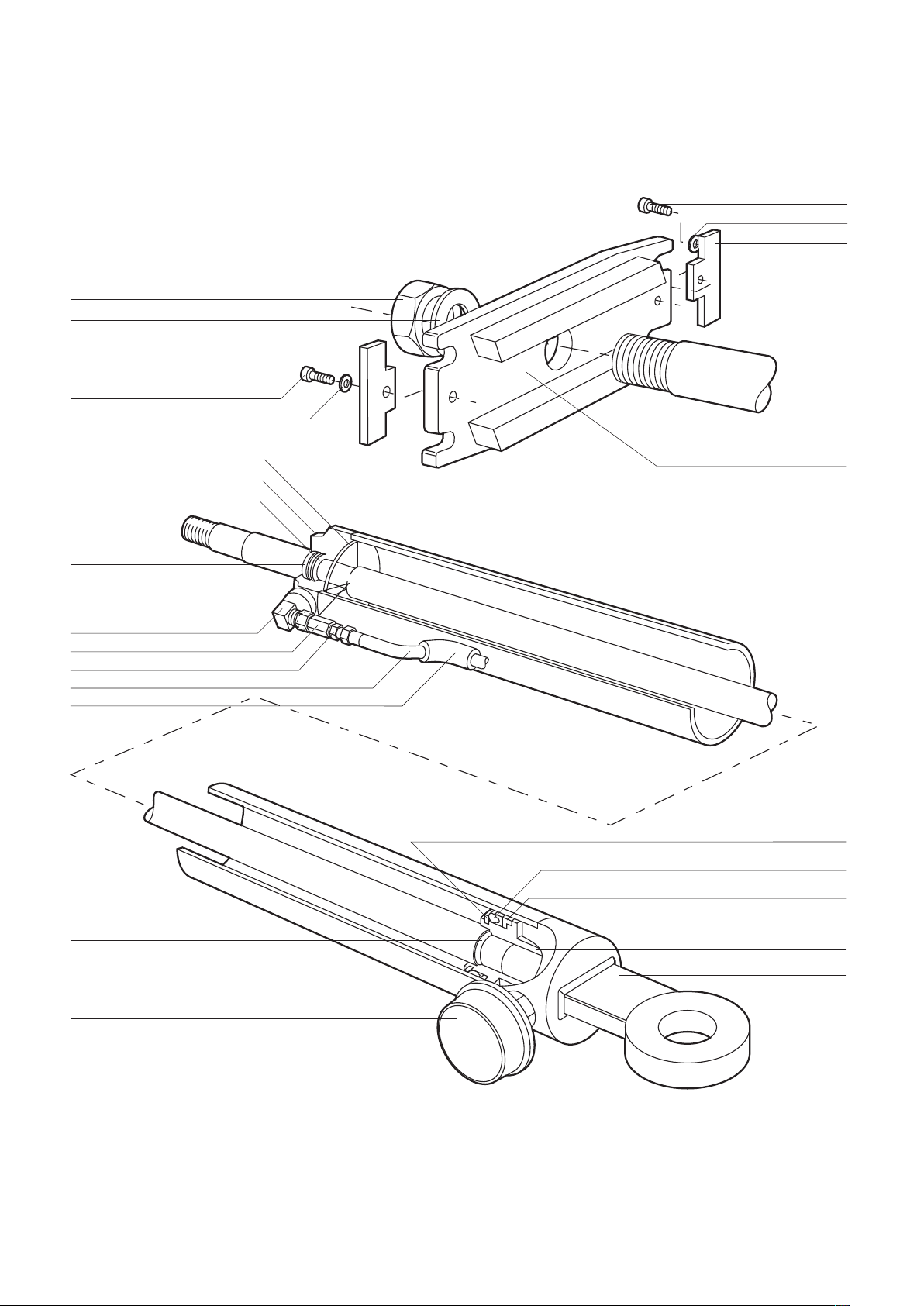
Cylinder removal
If oil is leaking from the cylinder breather or from
around the piston rod, the seals must be replaced.
1. Raise the hoist to a comfortable working height.
Engage the column hooks (and interlock pins) then
lower hoist until supported by the hooks. Check
engagement of the hooks.
2. Switch off and lock the isolator switch.
3. Disconnect the hydraulic hose from the cylinder.
Catch oil in a clean container under the cylinder.
Remove the four cable ties on the cylinder.
4. Extend the cylinder to drain the oil. Slide the cable
anchor plate along the cylinder rod to expose the
spanner flats and remove the Nyloc nut and cable
anchor plate.
Page 8

5. Remove the axle holding the cylinder and cable
pulleys in the track. Carefully support the cylinder.
Place cylinder on a clean bench.
6. Wrap the cylinder rod thread with masking tape.
Undo the cylinder gland and slide it off the rod,
taking great care not to let the rod drop down.
Extract rod from the cylinder. Be very careful, as the
piston passes over the thread inside the cylinder.
7. Examine and renew defective seals. Check piston
rod and cylinder walls for signs of scoring or flaking.
Renew if necessary. Thoroughly clean all parts.
8. Reassembly is a reversal of removal procedure, but
ensure all cylinder parts are clinically clean before
assembly. Lightly oil seals before fitting.
9. Tighten Nyloc nut to 105 Nm (75-80 ft lbs) torque.
Check cables are not twisted.
10.Switch on isolator, raise and lower hoist several
times to expel air from the cylinder. Top up the
reservoir.
Check the cylinder is free from leaks.
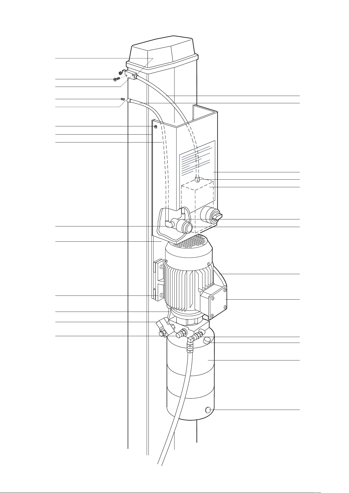
Hydraulic pump removal
To repair the hydraulic pump, the reservoir must be
removed. The pressure relief, check, and solenoid
valve are accessible without removing the reservoir.
1. Lower the hoist fully. Switch off and lock the isolator
switch.
2. Undo the four screws holding the top of the
reservoir to the main body and remove the reservoir.
3. The pump is now accessible for cleaning or repair
as necessary.
4. Installation is a reversal of the removal procedure.
Take care to ensure all parts are clinically clean.
5. Switch on isolator. Raise and lower hoist several
times to expel any air and ensure proper operation.
Check oil level.
Hydraulic hose replacement
If the hydraulic hose should burst, the flow control
valve at the cylinder will prevent the hoist from falling.
The hoist will lower at the normal speed
1. Option (a) if it is necessary to remove a vehicle
from the hoist urgently, disengage the column
hooks and lower the hoist to the floor (If possible).
Try to catch as much oil as possible.
After the hoist is lowered, remove the vehicle. Now
jack the hoist up to gain access to the hose under
the power track. Place supports under the track.
Clean up the spilt oil.
Option (b) If the hoist does not need to be lowered,
then engage the column hooks (and interlock pins),
and let the hoist lower until it is supported by the
hooks. Check engagement of the hooks visually.
Clean up the spilt oil.
2. With the hoist securely supported, switch off and
lock the isolator switch.
Disconnect the hose at both ends by undoing the
swivel nuts. Cut the four cable ties and remove the
clamp bracket, remove the hose and the plastic
sleeve from the hoist.
3. Remove the reducing bush, (and flow control valve)
and the sleeve and bracket from the burst hose.
Fit the parts to the new hose. Apply thread sealant
to the 1/4” BSP male end of the hose then fit and
tighten the reducing bush.
4. Feed the hose back into the track.
Connect the column end of the hose and tighten.
This will orientate the hose. Now connect the hose
at the cylinder end, making sure the hose is not
twisted when tightening the swivel nut.
Check the hose hangs straight down beside the
column and is not rubbing on it.
5. Position the plastic sleeve to protect the hose from
the edges of the hole in the track. Refit the four
cable ties and the clamp bracket.
6. Switch on the isolator then raise the hoist off its
supports. Raise and lower the hoist several times to
expel any air, and top up the reservoir
.

1. Motor will not run.
2. Motor runs but hoist will not lift.
3. Hoist squeaks when operating.
4. Hoist creeps down under load.
5. Safety clutches operate when
hoist is fully lowered to floor.
6. Hoist motor will not stop at full
height.
7. Hoist will not lower.
8. Column hook will not engage
freely.
9. Column hooks will not
disengage.
a) No power to hoist.
b) Thermal overload has tripped.
c) Top limit switch is damaged.
d) Wiring has loose connections.
e) Contactor faulty.
f) Raise switch faulty.
g) Motor faulty.
a) Lack of oil.
b) Hoist is overloaded.
c) Motor direction is wrong.
d) Solenoid valve stuck open.
e) Relief valve stuck open.
f) Burst hose.
g) Failure of motor - pump
coupling.
a) Dry clutch rods or clutch
pulleys.
b) Failed cable pulley bearing.
a) Dirt under solenoid valve seat.
b) Dirt under check valve seat.
c) Dirt under relief valve seat.
d) Leaking seal in cylinder.
e) Leak in pipework.
a) Hoist is on an obstruction.
b) Cables have stretched.
a) Cables have stretched.
b) Lack of oil
c) Limit switch arm is loose.
d) Limit switch is faulty.
a) Burst hose.
b) Clutches engaged.
c) Failed cable.
d) Solenoid valve not opening.
e) No power to hoist.
f) Solenoid faulty.
g) Lower switch faulty.
h) Wiring is loose.
a) Pivot is dry or corroded.
b) Spring is broken.
c) Air cylinder seized.
a) No air pressure.
b) Air line has leak.
c) Air line is kinked.
d) Air cylinder seal is leaking.
e) Air cylinder head seized.
Check the mains isolator is on and
fuses are OK.
Reset thermal overload.
Replace limit switch.
Tighten all connections.
Replace contactor.
Replace switch.
Replace motor.
Top-up reservoir.
Check load (4t maximum).
Reverse direction.
Clean valve assembly.
Clean valve.
Replace hose.
Replace coupling.
Lubricate with SAE 140 oil.
Replace pulley bearing.
Clean valve assembly.
Clean valve.
Clean valve.
Replace seal.
Raise hoist, remove obstruction.
Adjust cables.
Adjust cables.
Top-up reservoir.
Tighten arm.
Replace switch.
Replace hose.
Raise hoist to release clutches, adjust
cables.
Replace cables.
Clean and check operation of valve.
Check the main isolator is on and
fuses are ok.
Fit new solenoid.
Replace switch.
Tighten all connections.
Clean & lubricate pivot.
Replace spring.
Repair cylinder.
Check for air at filter/lubricator.
Find and fix leak.
Find and replace kinked tube.
Dismantle & repair cylinder.
Lubricate cylinder.
FAULT POSSIBLE CAUSE REMEDY
FAULT DIAGNOSIS
Page 10
Tighten fittings.

V16883
V16884
V16909
V15711
V16863
V16854
NMB1124.1
NMA1136.4
V16924
V17901P
V17901S
V17902P
V16850
V16844
PAP5030P10
V16868
V16864
V16867
V16866
V16865
1500.343E
SME1712.30
V16876
V16888
SME1706.12
V16886
V16842
V16846
SME906.12
AM1800.200
AM1400.125
V16859
WMA1006
WWA1007
V17907
V17906
V17908
V17909
AM1800.25
V17910
V17928
BME1106.35
NMA1106.1
163905.59
V16950
V17904L
V17904R
V17931
V17932
V17930
V17918
V17917
V17717
V16925
V16877L&R
SME1110.20
NMA1110.1
V18535
SME1506.16
DIN1500.7
COLUMNS
Columns, Right Hand
Columns, Left Hand
Columns, Power
Ferrule
Clutch Spring
Clutch Rod
M24 Hex. Nut, Plated
M36 Lock Nut, Plated
Column Cover, Finial
CROSS MEMBER ASSEMBLIES
Cross Member Assembly Power
Cross Member Assembly Slave
Cross Member Assembly, Welding
Axle Cross Member
Cable Pulley
Dia. 50 x 30 Plain Bearing
Clutch Assembly
Clutch Pulley
Clutch Axle
Clutch Pulley Tube
Clutch Pivot
E Circlip 438” Shaft
Cap Screw
Hook Bush
Cross Member Cover
M6 x Socket Head Cap Screw
Retaining Washer
Thrust Washer
Locking Plate
M6 x Socket Head Cap Screw
Cresent Clip 2” Shaft
Circlip 1 1/4” Shaft
Guide Bush
Washer 6 mm Flat
Washer
Hook Spring
Spring Guide
Swivel Block
Rod Pivot Bush
C. Circlip .250”
Air Cylinder Assembly
ø6 Tube 40 mm Long
Bolt M6 x 35L Hex. HD
Hex Nut M6
Shakeproof Washer
Cable Tie 190 mm
Hook Assembly Left
Hook Assembly Right
ø6 Tube 745 Long (Power)
ø6 Tube 785 Long (Slave)
ø6 Tube 2465 Long
Equal Tee Connector ø6 mm
Straight Adaptor ø6 mm Tube
Recess Cover
Ramp Assembly
Wheel Stop Left and Right
M10 x 20 Hex. Screw G8.8
Nut M10 x 1.5
Cable Retainer Nut
M6 x 16 Button Head Cap Screw
E-Circlip ø7 Shaft
1
1
1
1
1
1
1
1
1
1
1
1
1
1
1
1
1
1
1
1
1
1
1
1
1
1
1
1
1
1
1
1
1
1
1
1
1
1
1
1
1
1
1
1
1
1
1
1
1
1
1
1
1
1
1
1
1
1
1
1
2
1
1
4
4
4
4
8
4
1
1
1
2
2
2
2
2
2
2
2
10
2
2
2
4
2
4
2
2
2
2
2
4
2
2
2
2
4
4
2
1
16
6
6
2
1
1
1
1
1
2
2
2
2
1
24
4
2
2
1
1
2
3
4
5
6
7
8
9
10
11
12
13
14
15
16
17
18
19
20
21
22
23
24
25
26
27
28
29
30
31
32
33
34
35
36
37
38
39
40
41
42
43
44
45
46
47
48
48
49
50
51
52
53
54L&R
55
56
56A
56B
56C
Fig. No. Part No. Description Quantity Item no.

42
53
40
41
51
38
48
46
35
21
36
23
44
1
52
54R
57
10
55
56
63
3
2
9
64
11
58
54L
60
62
61
60
59
65
47
35
39
39
40
34
37
25
33
4
5
7
8
6
16
30
26
27
14
13
44
32
28
31
43
45
29
42
37
27
51
20
49
39
42
22
50
17
12
18
19
24
21
FIG. 1
Page 12
38
38
15
43

V16848
V17702
V18902
V18900
V18578
V16736
SME1106.20
V18577
V18916
V16889
V18914
WMA1006
NMA1106.1
V16946
V16934
V16935
V16936
V16937
V16844
PAP5030P10
V16842
V17716
V16845
V16846
SME906.12
BMA1106.50
28463M6
V17715
V16949
V17925
V17924
V17926
V17919
TRACK ASSEMBLIES
Track Assembly
Slave Track (recessed)
Track Power
Track Power (recessed)
Inner Toe Guard
Retaining Washer
Screw M6 x 20L
Toe Guard Bush
Outer Toe Guard
Ramp Angle
Ramp Angle-Outer
Washer 6mm Zn Plate Bright Steel
Nut Hex M6
Strap
Cable Assembly (B)
Cable Assembly (C)
Cable Assembly (A)
Cable Assembly (D)
Cable Pulley
Dia 50 x 30 Plain Bearing
Thrust Washer
Spacer
Axle Track
Locking Plate
M6 x 12 Countersunk Cap Screw
Screw M6 x 50 Len
Spring Washer M6
Spacer
Cable Tie 300M TY-RAP T
Male Elbow ø6 Tube
Bulkhead Adaptor
Coiled Tube
Guide Tube
1
1
1
1
1
1
1
1
1
1
1
2
2
2
2
2
2
2
2
2
2
2
2
2
2
2
2
2
2
2
2
2
2
1
1
1
1
4
16
4
4
2
2
2
2
2
1
1
1
1
1
6
6
7
2
2
2
2
2
2
2
4
1
1
1
1
57
57
58
58
59
60
61
62
63
64
65
66
67
68
69
70
71
72
73
74
75
76
77
78
79
80
81
82
83
84A
84B
84C
84D
Fig. No. Part No. Description Quantity Item no.
84B
84A
75
73
74
75
73
74
75
73
74
79
77
78
83
75
73
74
67
82
66
81
80
68
77
74
73
75
76
76
75
74
73
75
78
79
84D
84C
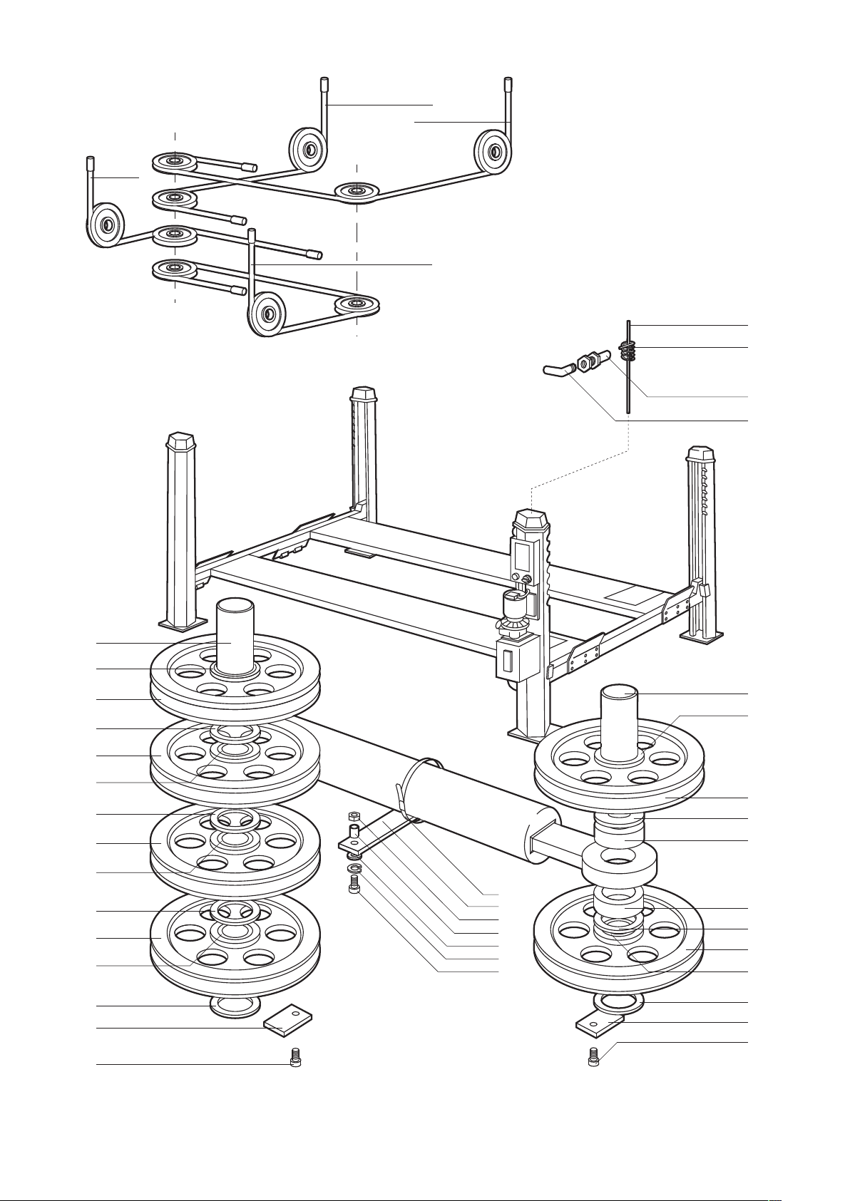
Ropes Detail
B (69)
D (72)
C (70)
A (71)
FIG. 2
Page 14

V20594
V16942
V20600
NSA1116.6
WWA1016
V17714
SME1710.25
28463.10M
V16928
V16928.1
V16928.2
V16928.3
V16928.13
V16928.14
V16928.4
V16928.5
V16928.6
V16928.7
V16928.8
V16928.9
V16928.11
V16928.12
V18556
V17711
V16908
V18907
V16901
Reducing Bush 1/2 - 1/4” BSP
Elbow 3/4” UNF x 3/8” BSP
Flow Control Valve
1” UNF Nyloc Nut, Plated
Washer 1” x 14G Bright Steel
Cable Retainer Plate
M10 x 25 Cap Screw
Spring Washer
Hydraulic Cylinder Assembly
Barrel and End Cap Assembly
Air Breather, Ryco No. 67
Seal Piston, Hallite Hallprene R10984S
Circlip DIN1400.0570
Wear Ring 040118
Piston
“O” Ring BS - 117
Piston Rod
“O” Ring Gland BS - 232
Gland
Seal Gland Ludowici H Seal `1250 1250.250
Wiper Rod
Insert, Nylon
Hydraulic Hose
Cable Anchor Plate, Assembly
4 Litre Container, Hydraulic Oil
Operation Manual
Warranty Card
3
3
3
3
3
3
3
3
3
3
3
3
3
3
3
3
3
3
3
3
3
3
3
3
-
-
-
1
1
1
1
2
2
2
2
1
1
1
1
1
1
1
1
1
1
1
1
1
1
1
1
3
1
1
85
86
87
88
89
90
91
92
93
94
95
96A
96
97
98
99
100
101
102
103
104
105
106
107
-
-
-
Fig. No. Part No. Description Quantity Item no.
88
106
85
87
86
103
104
105
102
101
90
92
91
100
99
95
88
89
91
92
90
96
96a
97
98
94
93
FIG. 3
Page 16
107


V17951P
V17951S
V17954R
V17952
V17124
V17159
V17954L
V17141
DIN1400.0160
V17125
V17939
GPS08.12
V17121
V17117
NMA112.4
V17941
V16939
SMA1106.12
NMA1106
SME1506.10
V17122
V17910
V17942
V17917
V17958
BME1106.35
163905.59
V17960
V17962
V17918
V17934
V17908
V17963
V17928
V17933
V15057
V17909
AM1800.25
1500.343E
WWA1007
V17956
V17957
V17110
V17158
V17130
V17128
V17133
V17134
V17120
SME1110.25
NMA1110.1
V17202
V17188
V17194
TEC4011 WHEELS FREE BEAM KIT
CROSS MEMBER ASSEMBLIES
Cross Member Assembly, Power
Cross Member Assembly, Slave
Hook Assembly, Right
Cross Member Welding Assembly
Interlock Link Tube
Label SWL 4 Tonnes at 800mm
Hook Assembly, Left
Hook Pivot
Circlip, Dia. 16mm Shaft
Interlock Plain Arm
Interlock Link Lever
Spring Pin, 1/8” x 3/4”
Interlock Handle Arm
Adjusting Screw
Lock Nut (Thin), M12
Interlock Pin
Handle
Hex Head Plated Screw M6 x 12
Hex Nut M6
Screw M6 x 10L Button Head
Link Bush
Air Cylinder
Elbow 1/8 BSP M + F
Straight Adaptor ø6 Tube
Spring Stop
M6 x 35 Hex Hd. Bolt
Shakeproof Washer
Air Pipe Assy.
Elbow Connector ø6 Tube
Equal Tee Connector ø6 Tube
ø6 Tube
Swivel Block
Straight Connector ø6 Tube
ø6 Tube
ø6 Tube
Label - Serial No.
Rod Pivot Bush
Crescent Clip ø1/4” Shaft
E Circlip ø0.438” Shaft
Washer 7/16” Flat
Spring
Spring Guide
WHEEL FREE BEAM ASSEMBLY
Wheels Free Beam
Label SWL, 2 Tonnes
Location Pad
Vee Pad
Extension Pad, 100mm
Extension Pad, 50mm
Support Bracket
M10 x 25 Hex. Screw G8.8
M10 Nut
Plastic Cap
Extension Pad 28mm
Rubber Pad
6
6
6
6
6
6
6
6
6
6
6
6
6
6
6
6
6
6
6
6
6
6
6
6
6
6
6
6
6
6
6
6
6
6
6
6
6
6
6
6
6
6
6
6
6
6
6
6
6
6
6
6
6
6
1
1
1
1
1
1
1
2
4
1
2
2
1
6
8
2
1
4
6
2
2
2
2
2
2
4
8
1
1
1
1
2
1
1
1
1
4
4
2
2
2
2
2
4
4
2
2
4
4
24
24
4
4
4
192
193
194
195
196
197
198
199
200
201
202
203
204
205
206
207
208
209
210
211
212
213
214
215
216
217
218
219
220
221
222
223
224
225
226
227
228
229
230
231
232
233
234
235
236
237
238
239
240
241
242
243
244
245
Fig. No. Part No. Description Quantity Item no.
This manual suits for next models
1
Table of contents
Other TECALEMIT Lifting System manuals

Popular Lifting System manuals by other brands


stellar labs
stellar labs SHUTTLE 84-12-13 G Assembly and installation manual

Terex
Terex Genie QS-12R Operator's manual

LSP inc.
LSP inc. LSP16H owner's manual

Harmar Mobility
Harmar Mobility HIGHLANDER II Installation & service manual

Terex
Terex Genie Z-45 XC Service and repair manual

Nussbaum
Nussbaum POWER LIFT HF 7000 Operating Manual and Inspection Book


