Tecfluid CU Series User manual

R-MI-CU100 Rev.: 2 English version
Series CU
Ultrasonic flowmeter
Instructions manual
The art of measuring

2
Thank you for choosing a product from Tecfluid S.A.
This instruction manual allows the installation, configuration,
programming and maintenance. It is recommended to read it before
using the equipment.
• This document shall not be copied or disclosed in whole or in any
part by any means, without the written permission of Tecfluid S.A.
• Tecfluid S.A. reserve the right to make changes as deemed
necessary at any time and without notice, in order to improve the
quality and safety, with no obligation to update this manual.
• Make sure this manual goes to the end user.
• Keep this manual in a place where you can find it when you need
it.
• In case of loss, ask for a new manual or download it directly from
our website www.tecfluid.com Downloads section.
• Any deviation from the procedures described in this instruction
manual, may cause user safety risks, damage of the unit or cause
errors in the equipment performance.
• Do not modify the equipment without permission. Tecfluid S.A. are
not responsible for any problems caused by a change not
allowed. If you need to modify the equipment for any reason,
please contact us in advance.
PREFACE
WARNINGS

3
TABLE OF CONTENTS
SERIES CU
1 INTRODUCTION ........................................................................... 6
2 INSTALLATION OF THE ELECTRONIC CONVERTER ...................... 6
2.1 Electrical connection ........................................................... 7
2.1.1 Power supply wiring ............................................... 8
2.1.2 Relay output wiring ................................................ 8
2.1.3 Analog output wiring ............................................... 9
2.1.4 Transducers wiring ................................................. 10
3 CONVERTER INTERFACE .............................................................. 11
4 MAIN MENU ................................................................................. 12
4.1 Passwords to access the menus ......................................... 12
5 TRANSDUCERS INSTALLATION .................................................... 14
5.1 Straight pipe run requirement .............................................. 14
5.2 Installation with the alignment guide .................................... 17
5.2.1 Straps preparation ................................................. 17
5.3 Fastening of the transducers ............................................... 17
5.4 Installation parameters ......................................................... 18
5.5 Language ........................................................................... 18
5.6 Transducer ......................................................................... 18
5.7 Units .................................................................................. 19
5.8 Pipe parameters ................................................................. 19
5.8.1 Outer diameter ...................................................... 19
5.8.2 Pipe material ......................................................... 20
5.8.3 Pipe thickness ....................................................... 20
5.8.4 Lining material ....................................................... 20
5.8.5 Lining thickness ..................................................... 21
5.9 Liquid ................................................................................ 21
5.10 Paths ................................................................................. 22
5.11 Installation and distance between the transducers ................ 23
5.12 Fixing the transducers ......................................................... 23
5.13 Signal strength ................................................................... 25
5.14 Distance ............................................................................ 25

4
5.15 Programs ........................................................................... 25
5.16 Transducers test ................................................................. 26
6 CONVERTER PROGRAMMING ...................................................... 26
6.1 Language ........................................................................... 27
6.2 Units .................................................................................. 27
6.3 Decimals ............................................................................ 28
6.4 Flow rate ............................................................................ 28
6.4.1 Cut off ................................................................... 28
6.4.2 Reversed flow rate .................................................. 28
6.4.3 Damping ................................................................ 29
6.4.4 Offset .................................................................... 29
6.5 Outputs .............................................................................. 31
6.5.1 Relay 1 and relay 2 ................................................. 31
6.5.2 Analog output ........................................................ 31
6.5.3 Configuration of the 4-20 mA output ....................... 32
6.5.4 Programming of the 4-20 mA output ....................... 32
6.5.5 Current calibration of 4 and 20 mA .......................... 32
6.6 Default screen ..................................................................... 33
6.7 Totalizer ............................................................................. 33
6.8 Backlight ............................................................................ 34
6.9 Programs ........................................................................... 34
7 SOFTWARE VERSION ................................................................... 34
8 SERIAL NUMBER .......................................................................... 35
9 DEFAULT SCREEN ........................................................................ 35
10 MAINTENANCE ............................................................................. 35
10.1 Fuse ................................................................................... 35

5
11 ASSOCIATED SOFTWARE WINSMETER CU .................................. 36
11.1 USB cable connection and drivers installation ...................... 36
11.2 Port connection ................................................................... 38
11.3 Access to installation and programming ............................... 38
11.4 Datalogger ......................................................................... 41
11.5 Visualization ....................................................................... 43
11.6 Simulation .......................................................................... 43
12 TECHNICAL CHARACTERISTICS .................................................. 44
13 SAFETY INSTRUCTIONS ............................................................... 45
13.1 Certificate of conformity TR CU (EAC marking) ..................... 45
14 DIMENSIONS ............................................................................... 46
15 TROUBLESHOOTING ................................................................... 48
ANNEX A Sound propagation velocity in some liquids ............................. 49
ANNEX B Sound propagation velocity in some solids .............................. 50
ANNEX C Flow rate table ...................................................................... 51

6
1 INTRODUCTION
The CU100 flowmeter is an electronic device that is based on ultrasonic signal transmission
through a pipe where a liquid is flowing. The working principle is called transit time. It
consists of placing two ultrasound transducers on a pipe and sending an ultrasonic signal
from the first to the second and back. The difference between the transmission and the
reception time is proportional to the flow velocity in the pipe. An associated electronic circuit
based on digital signal processing is responsible for converting the time difference in flow.
The device provides the following features:
• Non-invasive installation. The transducers are placed on the outside of the pipe
to measure the flow.
• Current output proportional to the flow rate and user programmable.
• Relay outputs programmable by the user.
• Graphic display with intuitive menus.
• No maintenance required.
2 INSTALLATION OF THE ELECTRONIC CONVERTER
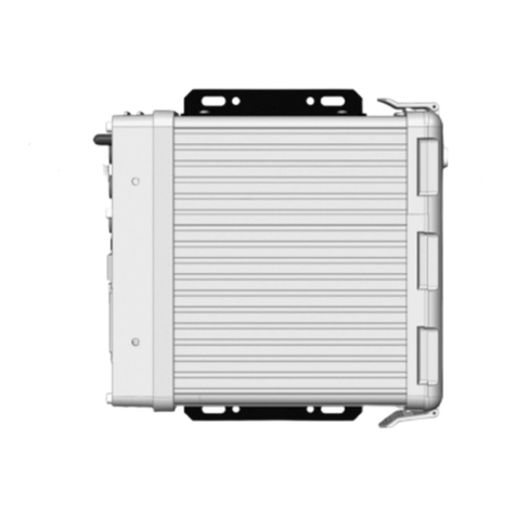
It is recommended to install the electronic converter on a wall near the point where the flow
rate needs to be measured, never on pipes .
To do this, remove the lid and use the 5 mm diameter holes indicated in the figure to fix the
converter to the wall.

7
2.1 Electrical connection
For the electrical connection, the CU100 converter has four terminal strips. To help in the
wiring of the equipment, the description of the terminals is marked on the printed circuit next
to each terminal strip.
For the electrical installation it is recommended to use multiple conductor cables with
individual cable sections in the order of 0.25 to 0.5 mm2in order to make it easier to
connect. It is better to maintain the cables with mains voltage (power supply) separated from
the cables with low level signals (4-20 mA, etc.).
Before starting the installation, check that the cable glands are the right size for the cables to
be used. This will guarantee the instrument will stay watertight. The cable glands used are
for cables with outside diameters between 3.5 mm and 10 mm (see page 46 for more
details).
To connect the cables, peel the outside insulation to free the inner cables. It is
recommended to tin the ends of the wires to avoid loose ends. Pass the cables through the
cable glands and screw down in the corresponding positions of the terminal strip. Once the
wiring is finished make sure that the cables are well gripped by the cable glands to maintain
the degree of protection.
Incorrect installation of the cable gland or inadequate cable placement can cause irreparable
damage to the converter.
IMPORTANT NOTE: In order to comply with the electrical safety requirements as per EN-
61010-1 (IEC 1010-1), the installation of the equipment must take into account the following:
• A mains switch must be provided to disconnect the equipment. This switch must
be marked as the disconnecting device for the equipment and be within easy reach
of the operator.
• The mains supply must have an earth line.
• The housing must not be opened when the instrument has mains supply
connected.
IMPORTANT NOTE: To ensure smooth operation of the equipment, it is recommended to
make the connection paying attention to the following points:
• Do not change or modify the junction cable between the transducers and the
converter.
• It is recommended to pass the transducer cables through a metallic conduit. The
two cables can go through the same conduit, but never together with other cables.
• For the output signals, use shielded cable when possible.
• Keep the cables away from strong sources of noise.

8
2.1.1 Power supply wiring
Before starting the installation of the instrument, check that the supply voltage available is
the same as marked on the label of the converter.
Terminal Description Relay
C1 Common Relay 1
NC1 Normally Closed Relay 1
NO1 Normally Open Relay 1
C2 Common Relay 2
NC2 Normally Closed Relay 2
NO2 Normally Open Relay 2
Terminal Power supply
Earth
NNeutral
LPhase
It is important to connect the mains earth due to the presence of a mains filter inside that
requires this connection.
2.1.2 Relay output wiring

9
The relay outputs are SPDT relays with potential free contacts (see characteristics in page
44).
The state of the relay contacts corresponds to the relay at rest.
The relay contacts are not protected in any way, and therefore the protections must be
installed externally as required in the application, taking into account the limitations of the
characteristics of such contacts. In the case of having inductive loads, and to extend the
working life of the contacts of the relays, it is recommended to use overvoltage protection
(VDR for AC and diodes for DC loads). In all cases a fuse or some type of short circuit
protection against short circuits should always be provided according to the needs of the
intended load.
2.1.3 Analog output wiring
Terminal
+mA (positive)
-mA (negative)
Passive mode: pins 2&3
Active mode: pins 1&2

10
The mA output is galvanically isolated. It can be active (which means that the receiver device
connected to it should have a passive input) or passive (which means that the receiver device
must provide the power supply for the current loop). It is recommended to use a receptor with
an input resistance of less than 700 Ω to guarantee correct operation.
To configure the analog output type (active or passive) there are two jumpers placed just
behind the terminal strip. For the passive mode the jumpers must be situated between pins
2 and 3 and for active mode the jumpers must be between pins 1 and 2.
NOTE: The analog output has protection against reversed polarity. Due to another
protection against over voltages, if a reversed supply voltage greater than 32 V is applied to
the loop, the equipment may be damaged.
2.1.4 Transducers wiring
Terminal
TR1 + Live (positive)
TR1 -Shield (negative)
TR2 + Live (positive)
TR2 -Shield (negative)
The transducers are identified as TR1 and TR2. Be sure to connect the cable TR1 in the TR1
terminals in the circuit board and the cable TR2 in the TR2 terminals. The exchange of the
transducers can result in a loss of precision of the values measured by the instrument.
Transducer cables are supplied with plastic indicators 1 and 2 to be connected to the
transducers TR1 and TR2 respectively.

11
3 CONVERTER INTERFACE
The CU100 converter has a graphic LCD and a keyboard with 12 push buttons.
The keyboard has ten numeric keys to introduce the values of installation and programming.
Two of these keys are used also as cursors, and finally there are two function keys.
The following figure shows the functionality of the converter keys.
To switch between flow rate, totalizer
and fluid velocity screens.
Into the menu, to scroll to the next
higher item.
To switch between flow rate, totalizer
and fluid velocity screens.
Into the menu, to scroll to the next
lower item.
To validate the data.
To enter into installation and
programming modes of the converter.
To exit from an informative text.
To return to the previous menu. To exit
from a screen without validating data.

12
To change the access password of
the programming menu, select
"Programming" in the main menu and
then "Password".
4 MAIN MENU
To access the main menu of the converter, press the key (OK). The following screen
appears:
To change the access password of
the installation menu, select
"Installation" on the main menu and
then "Password".
The "Installation" option allows the installation of the transducers, as explained in Chapter 5
of this manual.
The "Programming" option allows to program all parameters of the converter, as explained in
Chapter 6 of this manual.
From the "Reset totalizer" option, the user can return the totalizer to zero. When exiting the
menu, the totalizer will begin to accumulate again.
The options "Software Version" and "Serial Number" are informative and are discussed in
Chapters 7 and 8 of this manual.
4.1 Passwords to access the menus
To access the installation and programming menus, a password must be entered. At first
access, the default password is 0123.
The password for the installation menu may be different from the password for the program
menu. If you want to change any of these passwords, you must enter the corresponding
menu and once inside, access the submenu "Password".
Number of menu items
Selected item

13
When the "Password" option is selected, a screen to enter the new password appears.
Once entered, the new password is asked again to avoid possible inadvertent error.
If the re-entered password does not match the first one, the following error message
appears and the process should be carried out again.
If both passwords match, the following message is displayed:

14
5.1 Straight pipe run requirement
In order to obtain the maximum reading stability and accuracy, the point where the
transducers will be installed must meet some requirements regarding the straight pipe
sections before and after this point.
If the element that can disturb the flow profile is a fitting such as a flange, the straight pipe
section before and after the transducers should be minimum 5 x DN.
Some plant elements such as pumps, valves, etc., can create turbulences that distort the
flow profile resulting in incorrect measurements. In this case, the distances of straight pipe
without disturbing elements before and after the transducers can be higher, as shown in the
following pages:
5 TRANSDUCERS INSTALLATION
Make sure that the surface of the pipe where the transducers will be installed is clean and
free of rust or other dirt.
If possible, always install the transducers on a rising pipe, to ensure that it is always full of
liquid.
If the installation of the transducers is in a horizontal section, they should not be placed in
the top of the pipe, but in the area indicated in the figure below:

15
90º double elbow in
one plane
Valve
Pump
Disturbing element
before
the transducers
90º elbow
90º double elbow in
different planes
Tee
Reducer
Diffuser
Minimum distance between the
first transducer and the element

16
90º double elbow in
one plane
Valve
Disturbing
element after
the transducers
Minimum distance between the sec-
ond transducer and the element
90º Elbow
90º double elbow in
different planes
Tee
Reducer
Diffuser

17
Proceed in the same way for the second strap.
5.3 Fastening of the transducers
In order to fix the transducers it is necessary to calculate de optimum separation distance
between them. This distance depends on some parameters of the pipe and the liquid that
flows through it. The calculation of the separation between the transducers needs to enter the
following parameters.
Switch on the electronic converter. It is not necessary that the transducers are installed.
Press the (OK) key in order to enter the main menu.
With the keys (2) and (8), select “Installation”, and then validate with the key (OK).
5.2 Installation with the alignment guide
It is convenient to use the alignment guide (normally supplied for pipes from DN80 to
DN350), to guarantee that the transducers are perfectly aligned.
In case that the guide is not required or it is not supplied, the transducers can be installed
directly with the supplied straps (see page 24).
5.2.1 Straps preparation
Pass the free end of the strap through the two slots of one end of the guide.
Place the strap encircling the pipe, positioning the free end over the hooks and below the
screw. Snap the hooks on the tightest position possible. Tighten the connection with a
screwdriver until the guide is fixed rigidly, with no possible movement due to vibrations.

18
5.6 Transducer
You can choose the transducer model used in the installation.
In order to access to the transducers installation menu, a password must be entered. When
accessing the first time, the default password is 0123. For more details about the password,
see paragraph 4.1, page 12.
5.5 Language
You can choose the language in which all the menus will be seen.
Once the password is entered, and after pressing the key (OK), the first shown screen allows
to choose between the different options of the installation menu.
5.4 Installation parameters

19
5.7 Units
User can choose between metric and imperial units.
First, the outer diameter of the pipe must be entered.
5.8.1 Outer diameter
The outer diameter value must always be entered in millimetres.
If this parameter is not known, it can be calculated by measuring the circumference or
perimeter of the pipe.
5.8 Pipe parameters
It is necessary to know some data such as materials, thicknesses, etc., so that the
flowmeter can perform the necessary calculations to obtain the flow rate accurately.

20
5.8.4 Lining material
If the pipe has an internal lining, in this screen the lining material can be selected. In the same
way as in paragraph 5.8.2, if the material is not in the list, “Another material” must be selected
and the sound propagation velocity of the material must be entered.
In the event that the pipe does not have any internal lining, select “None”.
5.8.2 Pipe material
For the programming of the CU100 ultrasonic flowmeter, a list with several common pipe
materials is available. For each material the flowmeter has the necessary data to perform a
good measurement.
In the event that the pipe material is not on the list, you must select “Another material”, in the
last position in the list. In this case, the sound propagation velocity of the material must be
entered.
5.8.3 Pipe thickness
It is usually indicated on the pipe.
This manual suits for next models
1
Table of contents
Other Tecfluid Measuring Instrument manuals
Tecfluid
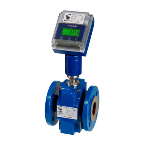
Tecfluid FLOMID Series User manual
Tecfluid
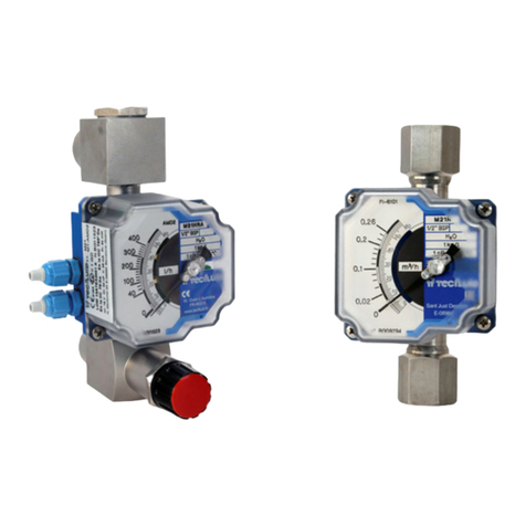
Tecfluid M21 User manual
Tecfluid
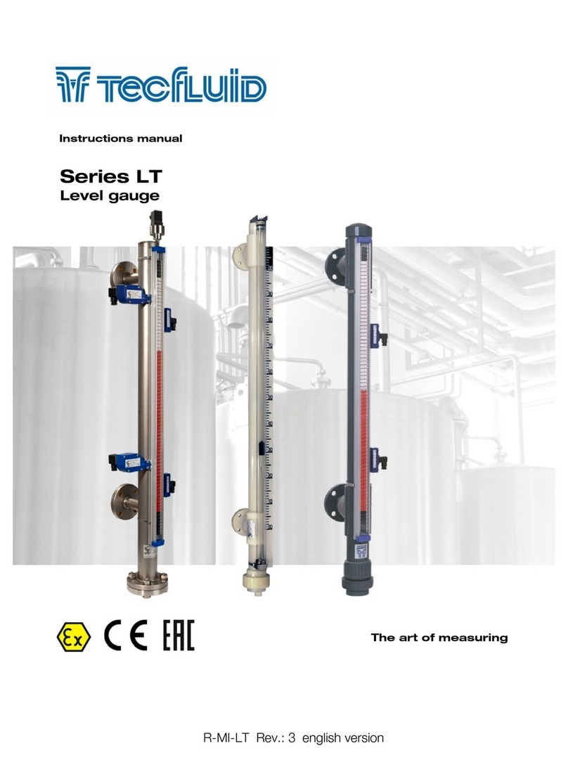
Tecfluid Series LT User manual
Tecfluid
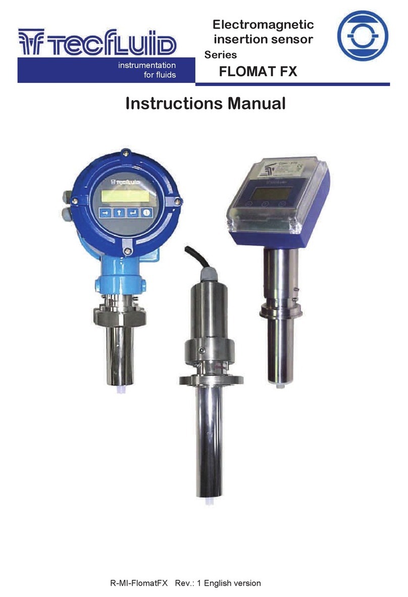
Tecfluid FLOMAT FX FlomatFX User manual
Tecfluid
Tecfluid LTDR series User manual
Tecfluid
Tecfluid AD Series User manual
Tecfluid
Tecfluid 2100 Series User manual

Tecfluid
Tecfluid LS Series User manual
Tecfluid
Tecfluid 60 M-1 Series User manual

Tecfluid
Tecfluid FLOMID Series User manual
