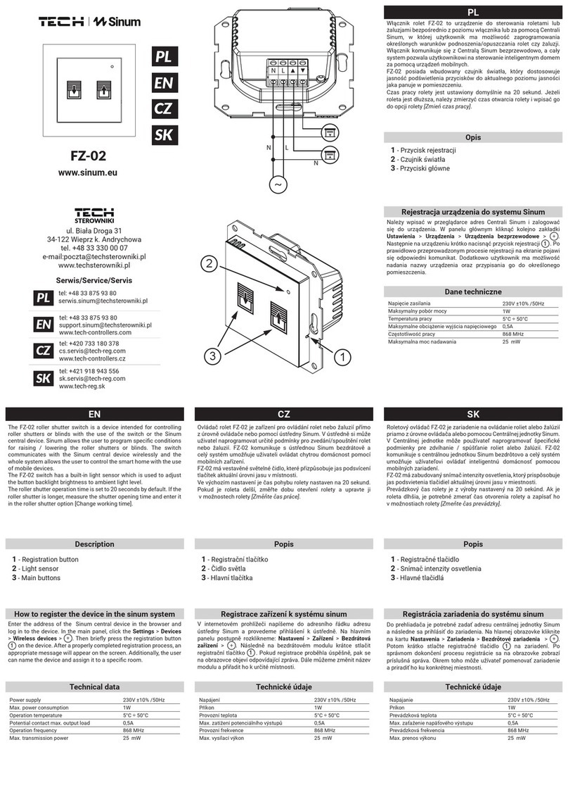
TECH ST-65 User manual

tech
- 1 -

ST-65 module GSM v1.0.7
Statement of compliance no 40/2011
We, the company TECH, headquartered in Wieprz 1047A, 34-
122 Wieprz, dec are with fu iabi ity, that the contro er ST 65
– GSM, produced by us, is comp iant
with the fo owing Directives of the European Union:
RTTE 1999/5/EC, LVD 2006/95/EC, EMC 2004/108/EC.
Harmonized norms, app ied to assess comp iance
with the basic requirements of the aforementioned EC
Directives:
PN-ETSI EN 301 511 V9.0.2: 2004
PN-ETSI EN 301 489-1 V1.5.1: 2007
PN-ETSI EN 301 489-7 V1.2.1: 2007
PN-EN 55022: 2006
PN-EN 55022: 2006/A1: 2008
PN-EN 61000-6-1: 2008
PN-EN 61000-6-3: 2008
PN-EN 60950-1: 2007
Co-owners:
Paweł Jura, Janusz Master
- 2 -

tech
I. SAFETY
During the installation and operation of Module ST-65 GSM the
following safety principles must be observed:
● a insta ation works shou d be performed after disconnecting vo tage
● before activating the modu e, it shou d be checked whether, in the vicinity,
there is no device susceptib e to GSM network radio frequency signa s such as
e.g. e ectronic medica apparatus
● it is advisab e that the distance between the working modu e and the heart
simu ator was over 20 cm
● it is required to strict y observe the prohibitions concerning mounting the
modu e in areas abe ed with a ban on using devices emitting radio waves
II. APPLICATION
The GSM modu e is a device cooperating with the contro ers of TECH
company, a owing to remote y contro the condition of the boi er operation
with the use of a mobi e phone. The User (via modu e ST-65) sha be notified
with an SMS message on every boi er contro er a arm. Additiona y, by
sending an appropriate SMS message at any time, the user receives a return
message with the information on the current temperature of a sensors. An
additiona advantage of the device is the possibi ity to change the set
temperature of any circu ation by means of a mobi e phone.
- 3 -

ST-65 module GSM v1.0.7
III. DESCRIPTION, MENU SCHEME
- 4 -
PLUS fitting
ANTENNA
GSM
EXIT,
CANCELLING
THE
SETTINGS
PLUG FOR COMMUNICATION
WITH THE CONTROLLER
ST-65 MENU
VIEW
MINUS fitting
ENTERING THE
MENU,
CONFIRMING
THE SETTINGS
POWER SUPPLY 9V DC
INPUT
CONTACT
CONNECTORS
TWO SENSOR
CONNECTORS
VOLTAGE
OUTPUT!

tech
IV. SIM CARD
Modu e ST-65 GSM wi not operate without a correct y inserted and
configured SIM card. In the case when the modu e detects no sim card, it wi
switch to standby mode, waiting for a card to be inserted. The SIM card may
be inserted ONLY at the time when the contro er screen disp ays the text:
"Insert the card
Press the button"
In the case of changing the sim card during modu e operation, use the
option in the modu e menu:
"Change the sim card"
After se ecting this option, the modu e wi switch to standby mode, waiting
for the card to be changed, wait for a message (as above). To insert the card,
unscrew four fixing screws and open the casing.
- 5 -
MENU CHANGING
THE SIM CARD
NOTIFICATION
GSM SETTINGS
WITH THE
CONTROLLER INDEPENDENTLYOPERATION MODE
INSERT
THE SIM CARD
TELEPHONE NUMBER SIM CARD PIN
NOTIFICATION
NO SUPPLY
ACTIVATED AUTHORIZATION PIN TIME OF NEXT
ALERT
SENSORS -
SETTINGS CONN. T1 SETT. CONN T2 SETT.
YES NO [1234] YES NO1 ÷ 300min, 0-off
T1 on off
(Active, Inactive)
T2 on off
(Active, Inactive)
TEMP. MAXIMUM TEMP. MAXIMUM
TEMP. MINIMUM TEMP. MINIMUM
CONF. INPUTS
CONF. INPUTS
(Active, Inactive)
ALARM WHEN...
(Short-circuit, Opening)
NAME...
[<<<<<<<<<<]
CONF. OUTPUTS OFF BY DEFAULTON BY DEFAULT
LANGUAGE ENGLISHPOLISH
+1<<<<<<<<<<<< +2<<<<<<<<<<<<

ST-65 module GSM v1.0.7
METHOD OF INSERTING THE SIM CARD:
After inserting the sim card, press any button, the modu e wi
activate and initiate a new card.
If the new card requires entering the pin code, you wi be asked to
enter the code. The modu e wi remember the code and in the case of
restarting, it wi use the pin saved in the memory.
The sim card pin can be set in the menu:
> >GSM settings> > Sim card pin
Note!!! The sim card pin is not masked in the modu e menu, in the
event of using the card for a different purpose, pin code shou d be
changed to a new one!!
NOTE!!! Replacement of the sim card in a different manner may
result in damaging the module!!!
V. COLLECTING DATA FROM THE CONTROLLER
Modu e ST-65 GSM may work independent y or with a contro er by
TECH company, equipped with RS communication and hand ing the
externa GSM modu e. After connecting, by means of RS232
communication cab e (with RJ p ugs, in a set) in the contro er insta er
menu, se ect, in the option " GSM module" >> activated.
- 6 -

tech
Modu e ST-65 GSM, after correct connection with a contro er, wi
receive va id parameters of its work. These parameters may be sent
back by the modu e, upon request, in the form of an sms message to
the user. The SMS is sent to any authorized phone number.
After sending to the modu e phone number the text "tech" or an
authorization pin, data with contro er working parameters wi be sent
back.
[Tech]
e.g.
tech
Name y: tech
Message of this type wi resu t in sending a return sms with the
current working parameters of the boi er.
No. name Value
Temp: CO 23 (current temperature)
Hot tap water 25 (current temperature)
1 Set CH 60 (set temperature)
2 Set HUW 40. (set temperature)
… … ...
The quantity and the type of sent data depend on settings and
operation mode of the contro er. Particu ar parameters are disp ayed in
a new ine, the phrases are separated with spaces (the ordina number
is a ways separated by a space from the set one).
To change the setting of boi er temperatures using a mobi e phone,
send an sms message to the modu e ST-65 phone number, with the
fo owing content:
[ in authorization] [s ace] [no. ] [s ace] [value] [;]
e.g.
9999 1 65 ;
2 60 ;
Namely: 9999 1 65; 2 60;
This command (if authorization pin is set to "9999") wi change the
set CH to 65 oC and the set HUW to 60 oC.
- 7 -

ST-65 module GSM v1.0.7
VI. CONTACT AND TEMPERATURE SENSORS
Modu e ST-65 has 2 additiona sensor connectors, one contact and one
contro ed output, operating independent y from the boi er contro er,
with a universa app ication:
1) Two connectors intended for connection of temperature sensors
(KTY) marked as T1 T2 (option – no sensors in the set). The scope
of sensors settings is within the range from - 10 to + 85oC.
2) One connector detecting short circuit/opening of contacts. Marked as
Wej (option – no cab e in the set). The connector enab es a very
broad scope of app ications (e.g. as an anti-burg ar sensor, inc uded
in the set with a imiting switch).
3) One contro ed Output. Marked as Wyj (e.g. a possibi ity to connect
additiona contactor to contro any e ectric circuit. See: page 14).
To activate the operation of the chosen connector, se ect and
high ight, in the submenu, the item "active". For joints of type T
(sensors), additiona y set the maximum and the minimum temperature,
the occurrence of which wi be signa ed by an sms message. For the
connector contact (Wej type) se ect the type of event (short circuit or
opening) the occurrence of which wi be signa ed by an sms message.
From that moment, the modu e wi inform:
➔ For connectors of type T, on measured temperatures i.e. the
current, the minimum, the maximum, measured in a given cyc e* and
a so on errors of sensors.
➔ For connectors of Wej type, in the case of occurrence of the
se ected event, that is detecting a short-circuit or opening of the
contact.
* cycle – is a period between subsequent sms messages.
- 8 -

tech
Wor ing parameters of sensors and sensor connectors are set in
module ST-65 by using the menu:
> Sensors settings
> > conf. inputs
> > > conf. Inputs
> > > > active
> > > > inactive
> > > alarm when …
> > > > short circuit
> > > > opening
> > > name …
> > > > [<<<<<<<<<<]
> > T1 connector settings.
> > > T1 on/off
> > > > active
> > > > inactive
> > > maximum temperature
> > > minimum temperature
> > > name …
> > > > [<<<<<<<<<<]
> > T connector settings.
> > > T on/off
> > > > active
> > > > inactive
> > > maximum temperature
> > > minimum temperature
> > > name …
> > > > [<<<<<<<<<<]
> Conf. Outputs
> > default on
> > default off
VII. DATA COLLECTION AND SETTINGS
1) Pin authorization:
The User can, at any time, change the "authorization pin" by
sending an sms message to the modu e number in the format:
[current pin authorization] [space] [pin] [space] [new pin authorization]
e.g.
1234 pin 9999
- 9 -

ST-65 module GSM v1.0.7
Name y: 1234 pin 9999
A message of this type wi change the modu e authorization pin
from 1234 to 9999 and wi send the return sms with the current
working parameters of the boi er.
!!!NOTE!!! the authorization pin is intended for changing settings
and working modes of the module. It is not recommended to
disclose it to third persons.
2) Activation/deactivation of alert notices:
The User can, at any time, activate or deactivate sending of a ert
information from the modu e by sending to the modu e number a
message in the format:
[current pin authorization] [space] [command]
e.g.
1234 Off
Name y: from 1234 Off
A message of this type wi deactivate sending of a ert messages
from the modu e. Sending messages in this format is equiva ent to
switching the option in the modu e menu:
>> Notification >> Activated >> No
or:
[current pin authorization] [space] [command]
e.g.
1234 On
Name y: 1234 On
A message of this type wi activate sending of a ert messages
from the modu e. Sending messages in this format is equiva ent to
switching the option in the modu e menu:
>>Notification>> Activated >> Yes
If notification is activated, the user shou d set the frequency of
cyc ica receipt of sms messages with current parameters of sensors
after the a arm occurrence:
- 10 -

tech
>> Notification >> Time of next alarm >> [0÷300min]
In the case of se ecting the va ue 0, the a arm cyc ica
reminder function sha be inactive.
3) Operation mode:
The user has the possibi ity of se ecting the type of incoming
information messages. In the menu > > Operation mode
after se ecting the option
>> independently
incoming sms information messages wi contain on y the data from
active contact and temperature sensors.
after se ecting the option
> > with the controller
incoming sms information messages wi contain data both from the
boi er contro er and from active contact and temperature sensors.
4) Output activation
Each GSM contro er by TECH company is equipped with one
output, which is p aced in the first p ace from the eft, ooking at the
view on page 3.
The user may, at any time, by means of an SMS text message, activate
or deactivate this output.
Three output states are possib e:
•Constantly activated.
•Activated for a specified time.
•Deactivated.
In order to activate output "Wyj" in a continuous mode, send a
message in the format:
[pin authorization] [W] [value] [;]
e.g.
9999 W 1 ;
- 11 -

ST-65 module GSM v1.0.7
Name y: 9999 W1;
Message of this type wi activate outputs "W" in continuous
operation mode.
In order to activate output "W" in time- imited mode, send a
message in the format:
[pin authorization] [W] [value] [space] [duration] [;]
e.g.
9999 W 1 30 ;
Name y: 9999 W1 30;
Message of this type wi activate outputs "W" for 30 minutes;
In order to deactivate output "W", send a message in the format:
[pin authorization] [W] [value] [;]
e.g.
9999 W 0 ;
Name y: 9999 W1;
Message of this type wi deactivate outputs "W" in a continuous
mode.
NOTE!!!
It is not possible to switch output "Wyj" to the operation mode of
the short-circuit sensor!!! (in that case it is possible to damage
the output)
- 12 -

tech
5) Change and activation of emergency numbers.
Entering emergency numbers.
The user can, at any time, change the a arm number. The change can
be performed by means of an SMS message or from the menu of
modu e ST-65 GSM.
The user can, at any time, change the "authorization pin" by sending a
message to the modu e number in the format:
[pin authorization] [n] [value] [;]
e.g.
9999 n 1 ;
Name y: 9999 N1;
The messages of this type wi change the first authorization number to
the te ephone number from which the user has sent the SMS message,
and wi send back an sms with contro er working parameters. Sending
a message of this type is equiva ent to a change in the menu of modu e
ST-65:
>GSM settings > Phone number> +1 <<<<<<<<<<<<or + 2
<<<<<<<<<<<<
Where, by means of up/down buttons, we se ect the te ephone number
of our choice, with the Menu button we begin editing the se ected phone
number.
The editing is divided into two stages:
•Editing the number, where, by means of up/down buttons, we change a
particu ar number character. With the Menu button, we move to another
character. After entering the proper phone number, we press the EXIT
button.
•The next stage is activating the number with up/down buttons, we
se ect whether the number is to be notified about a erts (Activate or
deactivate).
If the te ephone number differs from the number introduced, the
user is asked to confirm the changes.
- 13 -

ST-65 module GSM v1.0.7
Recharging
Fees for sending an sms are co ected in accordance with the
current price ist of a given operator. It shou d be remembered to
recharge the SIM card or to pay the subscription. Avai ab e funds on the
card can be contro ed after ogging in on the website of the GSM
network operator.
Technical data
No. Specification Unit
1Power supp y V 9V / DC
2Power consumption W 2
3Ambient temperature OC 5 ÷ 50
4Scope of a ert temperatures settings OC -10 ÷ 85
6Measurement error OC 1
8
9
Temperature strength of additiona sensors (KTY)
Communication cab e ength RS232
OC
m
-25 ÷ 90
2
Network status LED
Status SIM900 function
Off SIM900 Module deactivated
64ms On / 800ms Off SIM900 No network
64ms On / 3000ms Off SIM900 ithin the network range
64ms On / 300ms Off GPRS communication
- 14 -
Network status LED

tech
VIII. SAMPLE INSTALLATION
Modu e ST-65 is connected with the boi er contro er by means of a
four-core cab e RS232 with p ugs, type RJ (phone p ug). Optiona y,
there is a possibi ity to buy and connect additiona e ements (Re ay,
Contact and Temperature sensors).
- 15 -

ST-65 module GSM v1.0.7
IX. Battery re lacement: (in the case of damage or loss of
utility ro erties)
Modu e ST-65 GSM is equipped with a Li-ion Battery.
It is accepted to rep ace the battery on y with the one which meets the be ow
specification. Incorrect inserting of the battery can cause damage to the battery or
device.
Specification:
Type: 1044
Capacity: 600mAh
Vo tage: 3.7V
Bui t-in PCB protection against excessive discharging, overcharging or short-
circuit.
Dimensions: diameter 10.04mm, ength 46.75mm (+/-0.3mm)
NOTE! During rep acement, pay specia attention to po arization.
– The battery shou d be used on y in accordance with its intended use.
– Never use a battery which is damaged or waste.
– Short-circuit of the po es is not accepted. This can take p ace accidenta y. C amp
short-circuit can cause damage to the battery or to the device connected to it.
Disposing of waste batteries and accumulators (used in EU member countries and in
other European countries having their own collection systems).
Never throw a battery into the fire!
Waste batteries shou d be ob igatori y sent for recyc ing or disposed of, according to the oca
regu ations. It is not a owed to throw a battery to municipa waste containers.
Care for the natural environment is of primary importance for us. The awareness that we
manufacture e ectronic devices ob igates us to practice environmenta -friend y disposa of used
e ements and e ectronic equipment. As a resu t, the company has received a registry number
assigned by the Nationa Inspector of Environmenta Protection. The symbo of a crossed out
rubbish bin on a product means that the product must not be thrown out to ordinary waste bins.
By segregating waste intended for recyc ing, we he p protect the natura environment. It is the
user's responsibi ity to transfer waste e ectrica and e ectronic equipment to the se ected
co ection point for recyc ing of waste generated from e ectronic and e ectrica equipment.
- 16 -

tech
In order to develop and improve the product, please send any comments concerning program errors or
abnormal controller operation states directly to the address:
SERWIS TECH: [email protected] phone no. (+48 33) 8759380.
- 17 -

ST-65 module GSM v1.0.7
- 18 -

tech
Contents
I. SAFETY.......................................................................................................................................................3
II. APPLICATION...........................................................................................................................................3
III. DESCRIPTION, MENU SCHEME..........................................................................................................4
IV. SIM CARD................................................................................................................................................5
V. COLLECTING DATA FROM THE CONTROLLER...............................................................................6
VI. CONTACT AND TEMPERATURE SENSORS......................................................................................8
VII. DATA COLLECTION AND SETTINGS...............................................................................................9
1) Pin authorization:....................................................................................................................................9
2) Activation/deactivation of alert notices:..............................................................................................10
3) Operation mode:...................................................................................................................................11
4) Output activation..................................................................................................................................11
5) Change and activation of emergency numbers.....................................................................................13
VIII. SAMPLE INSTALLATION.................................................................................................................15
IX. Battery replacement: (in the case of damage or loss of utility properties)..............................................16
- 19 -

tech
- 20 -
Table of contents
Other TECH Control Unit manuals
