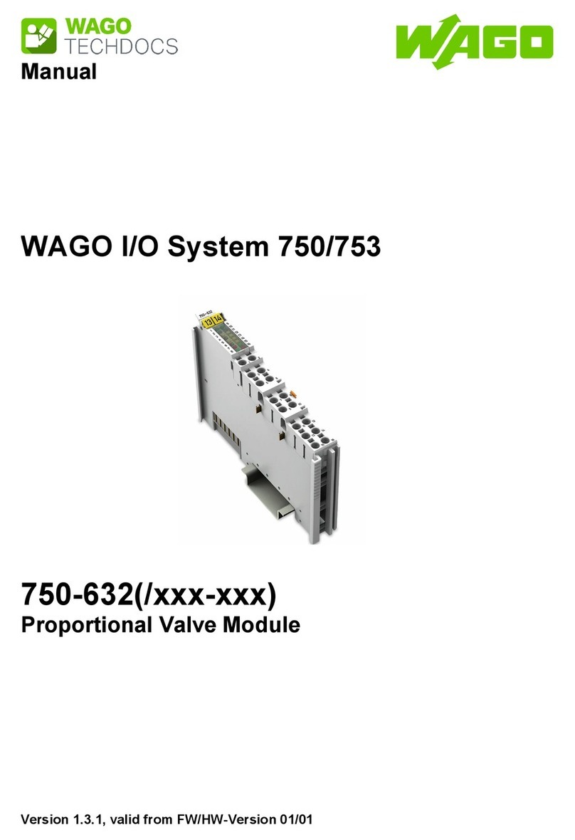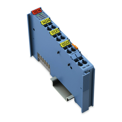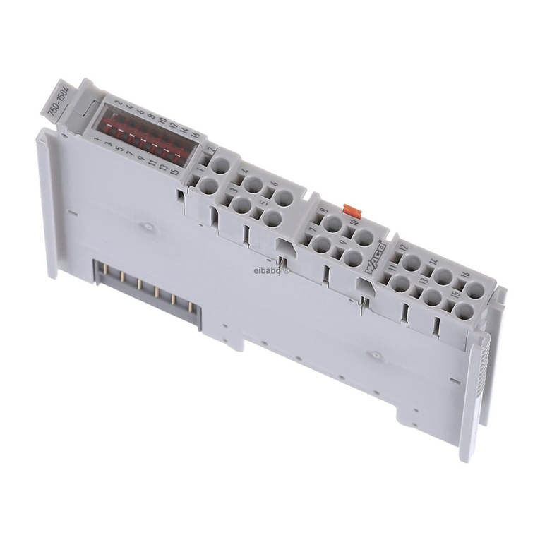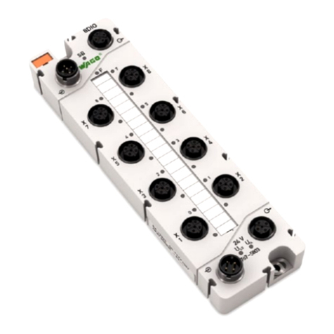
WAGO-I/O-SYSTEM 750 Table of Contents 3
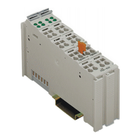
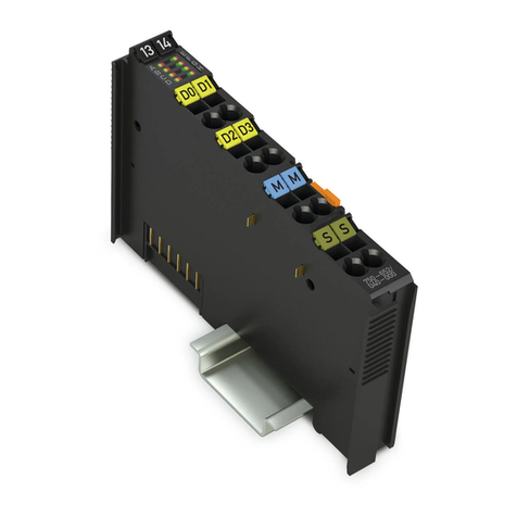
753-466 2 AI 4-20 mA S.E.
Manual
Version 1.5.0
Pos: 5 /D o ku ment ati on allg e mei n /Ver zei c hni ss e/I nh alt s verz ei ch nis - Ü b er schr if t oG und Ver zei ch nis @ 3\mod_1219151230875_21.docx@21063 @ @ 1
Table of Contents
1Notes about this Documentation................................................................. 5
1.1 Validity of this Documentation................................................................. 5
1.2 Copyright................................................................................................... 5
1.3 Symbols..................................................................................................... 6
1.4 Number Notation....................................................................................... 8
1.5 Font Conventions ...................................................................................... 8
2Important Notes ........................................................................................... 9
2.1 Legal Bases ............................................................................................... 9
2.1.1 Subject to Changes ............................................................................... 9
2.1.2 Personnel Qualifications....................................................................... 9
2.1.3 Use of the WAGO-I/O-SYSTEM 750 in Compliance with Underlying
Provisions ............................................................................................. 9
2.1.4 Technical Condition of Specified Devices......................................... 10
2.2 Safety Advice (Precautions).................................................................... 11
3Device Description ..................................................................................... 13
3.1 View ........................................................................................................ 15
3.2 Connectors............................................................................................... 16
3.2.1 Data Contacts/Internal Bus................................................................. 16
3.2.2 Power Jumper Contacts/Field Supply ................................................ 17
3.2.3 CAGE CLAMP®Connectors ............................................................. 19
3.3 Display Elements .................................................................................... 20
3.4 Schematic Diagram ................................................................................. 21
3.5 Technical Data ........................................................................................ 22
3.5.1 Device................................................................................................. 22
3.5.2 Supply................................................................................................. 22
3.5.3 Communication .................................................................................. 22
3.5.4 Inputs .................................................................................................. 22
3.5.5 Connection.......................................................................................... 23
3.5.6 Climatic Environmental Conditions................................................... 23
3.6 Approvals ................................................................................................ 24
3.7 Standards and Guidelines........................................................................ 25
4Process Image............................................................................................. 26
5Mounting..................................................................................................... 28
5.1 Mounting Sequence................................................................................. 28
5.2 Inserting and Removing Devices ............................................................ 29
5.2.1 Inserting the I/O Module .................................................................... 29
5.2.2 Removing the I/O Module.................................................................. 30
5.3 I/O Modules with Pluggable Wiring Level (Series 753) ........................ 31
5.3.1 Coding ................................................................................................ 33
5.3.2 Plug Removal ..................................................................................... 35
6Connect Devices ......................................................................................... 36
6.1 Connecting a Conductor to the CAGE CLAMP®................................... 36
6.2 Connection Examples.............................................................................. 37
6.2.1 2-Wire Connection 0 V ...................................................................... 37
