Operating the techgrow Humi Dual Pro:
When the humidity in a room drops below the set
value (setpoint), the humidifi er will be activated
(right socket). When the humidity in the room
reaches above the set value (setpoint),
the dehumidifi er will be activated (left socket).
Example:
The humidity “set” is at 60%.
The humidity “hys” is at 3%.
The current humidity value in the room is for ex-
ample, 63%, that is 3% higher than the humidity
set, so the humidifi er is deactivated. All LED lights
are now switched off .
Humidify
The humidity slowly drops to 60%: nothing
happens.
Only when the value drops below the humidity
“set” minus the hysteresis, the humidifi er will
be activated. In this case, the humidifi er will be
activated at 60% - 3% = 57%. The LED will now
switch to red.
The humidity level will now rise and when the
value reaches 60% + 1% = 61%, the humidifi er
will be deactivated again. The red LED will now
switch off .
Dehumidify
The humidity will now slowly rise to 63%: nothing
happens.
Only when the value rises above the humidity
“set” plus the hysteresis, the dehumidifi er will be
activated.
In this case, the dehumidifi er will be activated at
60% + 3% = 63%. The LED will now switch to red.
The humidity now drops. When the value reaches
60% - 1% = 59%, the dehumidifi er will be
deactivated again. The red LED will now switch
off .
Meaning of the LED
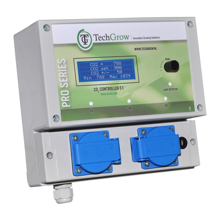
• Light detected: light indicator (under the PTB).
• Dehumidify: Dehumidifi er is active.
• OK: indicates that the humidify lies
between set+hys and set-hys.
• Humidify: Humidifi er is active.
Operating and adjusting the Humi Dual:
All settings are done with the Push & Turn Button
(PTB). By pushing the button you will enter the
set-up menu. An arrow will appear on the left side
of the display =>.
When activating the Humi Dual Pro the
following will appear on the display:
TechGrow
Humi Dual
Pro-Series
Software v. 1.x
After a few seconds the start screen is shown:
RH = 47%
RH set 50%
RH +/- 3%
Min 43% Max 57%
Here you can see all data relevant to the Humi
Dual Pro at a glance.
By keeping the PTB pressed down in this startup
screen for at least fi ve seconds, the RH min/max
values are reset and set to the current
measurement value.
Enter the menu by briefl y pushing the button:
TMP = 25.5 C
=> RH = 32%
CO2 = 549 ppm
This naturally only shows the values of connected
sensors.
Without connecting an S-2 or S-4, the CO2 value
will not be shown.
By rotating the PTB in the setup menu, you can
place the arrow in front of the various sensor val-
ues. Press the PTB once to fi nd out more about
this specifi c sensor. Only the min/max values are
indicated for “TMP” and “CO2” sensors:
Line 1: The minimum measured value of the
connected sensor.
Line 2: The maximum measured value of the
connected sensor.
Line 3: The min/max values are reset back to the
current measured values of the connected sensor.
Line 4: << BACK <<
These measurements will not be saved during
power outages
For RH (humidity), more information is provided:
RH set 50%
RH +/- 3%
>>NEXT>>
Here you can set the set-point and hysteresis for
the desired RH value.
Adjusting setpoint
Put the cursor (=>) in front of the “RH set” line by
rotating the PTB, and then push the PTB.
A blinking square will appear in front of the RH set
value.
By rotating the PTB, you can set the desired RH
concentration.
Confirm this value by pushing the PTB or wait a
few seconds for automatic confirmation
Adjusting hysteresis (BANDWITH)
Push the PTB once. An arrow (=>) will appear on
the display in front of RH set.
Place the arrow in front of RH +/- by rotating the
PTB. Push once to confi rm.
A blinking square (■) appears in front of
RH +/-.
Set the desired humidity hysteresis
(advise: 3%) by means of the PTB.
Confi rm your selection by pushing the PTB or wait
several seconds for automatic
confi rmation.
By selecting the “>> NEXT >>” line and pushing
the PTB, you will enter the RH Min-Max menu
Replacing the fuse:
If a short circuit occurs by overload of one of the
outlets, the fuse will blow.
These fuses have been placed at the bottom of
the controller, right of each socket.
By pressing the fuse holder slightly with a
screwdriver and turning it counter-clockwise a
quarter turn, the fuse holder can be removed.
Place a new fuse with similar specifi cations in the
fuse holder and put the fuse holder back into the
casing.
Then press the fuse back in slightly, and tighten it
again with a clockwise quarter turn.
Two new (diff erent!) fuses are provided, one for
each exit. Make sure you use the right
fuse for replacement. Damage caused by using
the wrong fuse is not covered by the
manufacturer’s guarantee.
TECHNICAL SPECIFICATIONS
Power supply: 100 to 240 Volt (automatic)
Power frequency: 50 to 60 Hz
Consumption: 3 Watt (with sensor, without humidifi er/dehumidifi er)
Maximum load: 1500 Watt (max 6A)
Range humidity set: 10 – 90% relative humidity
Range humidity +/-: 0 – 5% humidity
Measurement frequency: 1 measurement per second.


