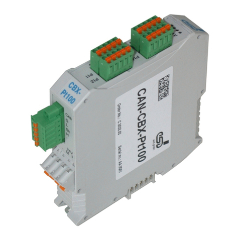
Technica Engineering 100Base-T1 SFP User manual

User Manual
100Base-T1 –SFP Module
Version 0.5
05. March 2018
Technica Engineering GmbH
Fax: +49-89-200-072430
Leopoldsrtaße 236
Email:
Info@technica-engineering.de
80807 München
www.technica-engineering.de
Germany

Index
1Feature List ....................................................................................................................3
2Warranty and Safety Information ....................................................................................4
3Pinning ...........................................................................................................................5
4Startup and Configuration...............................................................................................6
4.1 Startup.....................................................................................................................6
4.2 Self-Configuration ....................................................................................................7
5I2C interface...................................................................................................................6
5.1 I2C Configuration ………………………………………………………………………… 7
5.2 I2C Memory Map …………………………………………………………………………. 7
5.3 Device addressing and operation ……………………………………………………….…. 8
5.3.1 Current address read …………………………………………………………………. 8
5.3.2 Random read ………………………………………………………………………….. 8
5.3.3 Sequential read ……………………………………………………………………….. 9
5.3.4 Byte write ………………………………………………………………………………. 9
5.3.5 Sequential write ……………………………………………………………………… 9
6 Frequently asked questions - FAQ…………………………………………………………. 10
7Contact.........................................................................................................................11
Page 2of 12

1 Feature List
The Technica Engineering 100Base-T1 SFP module fits into a standard Small Form-factor
Pluggable slot. ®
It uses the SGMII and generates 100 Mbit/s full-duplex BroadR-Reach .
After PowerUp it self-configures to Automotive BroadR-Reach®.
Registers of the integrated transceiver are accessible via I2C interface for diagnosis and
re-configuration.
One Link LED shows link status.
Power requirement:
3.3 Volt DC
+/- 0.03 Volt
Power dissipation:
0.5709 W
Size:
68 x 14 x 14 mm
Wight:
0,1 Kg
International Protection
IP 2 0
Operating Temperature
0 to +70 °Celsius
"BroadR-Reach is a trademark of Broadcom Limited"
Page 3of 12

2 Warranty and Safety Information
Before operating the device, read this manual thoroughly and retain it for
your reference.
Use the device only as described in this manual.
Use only in dry conditions.
Do not apply power to a damaged device.
Do not open the device. Otherwise warranty will be lost.
This device is designed for engineering purpose only.
Special care has to be taken for operation.
Do not use this device in a series production car.
As this device is likely to be used under rough conditions, warranty is limited
to 1 year.
Manufacturer liability for damage caused by using the device is excluded.
Page 4of 12

3 Pinning
The BroadR-Reach®line is connected by a Molex connector.
Hardware Version 2.4 and above use:
- Molex 0533250260 Header 2.0mm
- Molex 510900200 Housing
-Molex 50212-8000 Crimp Contact
Pin
Function
Pin
Function
1
BroadR-Reach®Plus
2
BroadR-Reach®Minus
SFP Socket connector:
Pin
Function
Pin
Function
1
GND
20
GND
2
Tx_Faul –Connected to GND
19
SGMII_TXD_N
3
n.c.
18
SGMII_TXD_P
4
I2C_DAT
17
GND
5
I2C_CLK
16
3.3 Volt
6
GND
15
3.3 Volt
7
n.c.
14
GND
8
Rx_Los –Connected to GND
13
SGMII_RXD_P
9
n.c.
12
SGMII_RXD_N
10
GND
11
GND
Page 5of 12

4 Startup and Configuration
4.1 Startup
After 3.3 Volt power is applied, the SFP module starts up and self-configures the
BCM54811S transceiver by I2C interface. This lasts 100ms. In the first 100ms the
processor on the module acts as I2C master. Do not apply any master activity on
the bus during this time!
4.2 Self-Configuration
The SFP Module configures itself to Automotive BroadR-Reach®after power up.
Master / Slave Configuration is done according to the DIP switch on the bottom of the device.
To reconfigure the DIP switch the lock has to be opened (see picture).
ON/left =Master
OFF/right = Slave
Page 6of 12

5 I2C Interface
5.1 I2C configuration
I2C can be used 100ms after the power up of the module.
The module operates with fSCL up to 100kHz without requiring clock stretching.
The module may clock stretch with fSCL greater than 100kHz and up to 400 kHz.
The module processor listens as slave on the 7-bit address 0x50.
Note: b1010 000X = 0xA0
Read access beyond address 95 will return 0x00.
The BCM54811S transceiver can be accessed at I2C slave 7-bit address
0x40. Note: b1000 000X = 0x80
Read access to register 0x02 will always return 0x03, 0x62 (Device ID).
Write access to register 0x00 with value 0x02, 0x00 will configure the module to BR Slave.
Write access to register 0x00 with value 0x02, 0x08 will configure the module to BR Master.
For a complete register map please have a look at the BCM54811S datasheet
(Broadcom NDA required).
5.2 I2C map register
Memory Map (read only registers):
Data Bytes
Byte Number
Comment
0x03,
0
Identifier SFP
0x04,
1
Ext. Identifier
0x80,
2
Connector
0x00, 0x00, 0x00, 0x00,
3-6
Transceiver high
0x00, 0x00, 0x00, 0x00,
7-10
Transceiver low
0x00,
11
Encoding
0x01,
12
Bitrate Nominal in 100 MBit
0x00,
13
Reserved
0x00,
14
Link Length Fiber
0x00,
15
Link Length Fiber
0x00,
16
Link Length Fiber
0x00,
17
Link Length Fiber
0x0A,
18
Link Length Copper in meter
0x00,
19
Reserved
'T', 'e', 'c', 'h', 'n', 'i', 'c', 'a', ' ', 'E', 'n', 'g', '.', ' ', ' ', ' ',
20-35
Vendor Name
0x00,
36
Reserved
0x00, 0x00, 0x00,
37-39
Vendor ID
'1', '0', '0', 'B', 'A', 'S', 'E', '-', 'T', '1', ' ', ' ', ' ', ' ', ' ', ' ',
40-55
PartNumber
0x00, 0x00, 0x00, 0x00,
56-59
Revision Number
0x00, 0x00, 0x00,
60-62
Reserved
0xBC,
63
Check Code for Field 0-62
0x00, 0x00,
64-65
Options
0x00,
66
Bitrate max
0x00,
67
Bitrate min
0x00,
0x00,
0x00, 0x00,
0x00, 0x00,
0x00, 0x00,
0x00, 0x00,
0x00,
0x00, 0x00,
0x00, 0x00, 0x00,
68-83
Serial Number String
0x00, 0x00, 0x00, 0x00,
84-87
Date Code high
0x00, 0x00, 0x00, 0x00,
88-91
Date Code low
0x00, 0x00, 0x00,
92-94
Reserved
0x42
95
Check Code Extended for Field 64-94
Page 7of 12

5.3 I2C Device addressing and operation
5.3.1 I2C Current address read
The current read operation only requires the device address read word to be sent. When
the acknowledge is received from the SFP module, the current address data word is serially
clocked out.
Example: Read the current address of the SFP module (b1010000X)
<-I2C_device ->
H
S
M
L
R
N
S
O
T
S
S
E
A
T
S
A
B
B
A
C
O
T
R
D
K
P
T
1
0
1
0
0
0
0
1
0
X
X
X
X
X
X
X
X
1
S
A
M
L
F
C
S
S
P
K
B
B
<-
DATA WORD->
5.3.2 Random address read
The random address read requires two operations to perform the read.
Example: Read a random address of the SFP module (b1010000X)
First a write operation to specify the address desired to read:
<-I2C_device ->
<-I2C Memory address->
H
S
M
L
W
M
L
O
T
S
S
R
S
S
S
A
B
B
I
B
B
T
R
T
T
E
1
0
1
0
0
0
0
0
0
X
X
X
X
X
X
X
X
0
S
A
A
F
C
C
P
K
K
Page 8of 12

Then a read operation to read the previous address specified:
<-I2C_device ->
H
S
M
L
R
N
S
O
T
S
S
E
A
T
S
A
B
B
A
C
O
T
R
D
K
P
T
1
0
1
0
0
0
0
1
0
X
X
X
X
X
X
X
X
1
S
A
M
L
F
C
S
S
P
K
B
B
<-
DATA
WORD->
5.3.3 Sequential read
The sequential reads are started by either a current word address read or a random address
read. To specify a sequential read, the host responds with an acknowledge instead of a stop
after each data word.
First a write operation to specify the address desired to read:
<-I2C_device ->
<-I2C Memory address->
H
S
M
L
W
M
L
O
T
S
S
R
S
S
S
A
B
B
I
B
B
T
R
T
T
E
1
0
1
0
0
0
0
0
0
X
X
X
X
X
X
X
X
0
S
A
A
F
C
C
P
K
K
Then the read operations:
<-I2C_device ->
H
S
M
L
R
A
N
S
O
T
S
S
E
C
A
T
S
A
B
B
A
K
C
O
T
R
D
K
P
T
1
0
1
0
0
0
0
1
0
X
X
X
X
X
X
X
X
1
X
X
X
X
X
X
X
X
1
S
A
M
L
M
L
F
C
S
S
S
S
P
K
B
B
B
B
<
-DATA WORD n->
<-DATA WORD n+1->
5.3.4 Byte write
The write operation requires 8-bits of data word address following the device address
write word and acknowledgement.
Page 9of 12

Example: Byte write operation into the SFP module (b1010000X)
<-I2C_device ->
<-MEMORY ADDRESS->
<-DATA WORD->
H
S
M
L
W
M
L
M
L
S
O
T
S
S
R
S
S
S
S
T
S
A
B
B
I
B
B
B
B
O
T
R
T
P
T
E
1
0
1
0
0
0
0
0
0
X
X
X
X
X
X
X
X
0
X
X
X
X
X
X
X
X
0
S
A
A
A
P
C
C
C
F
K
K
K
5.3.5 Sequential write
The sequential write is started in the same way as a single byte write, but the host master
does not send a stop condition after the first word is clocked in.
<-I2C_device ->
<-MEMORY ADDRESS->
<-DATA WORD 1->
<-DATA WORD 2->
H
S
M
L
W
M
L
M
L
M
L
S
O
T
S
S
R
S
S
S
S
S
S
T
S
A
B
B
I
B
B
B
B
B
B
O
T
R
T
P
T
E
1
0
1
0
0
0
0
0
0
X
X
X
X
X
X
X
X
0
X
X
X
X
X
X
X
X
0
X
X
X
X
X
X
X
X
0
S
A
A
A
A
P
C
C
C
C
F
K
K
K
K
Page 10 of 12

6 Frequently Asked Questions –FAQ
Q: What is the maximum BroadR-Reach®cable length?
A: The BroadR-Reach®Port is optimized for automotive UseCase. The maximum
line length for each BroadR-Reach®segment is limited to 10 meters.
Q: The BR Link LED is lit but I have no valid BR Link. What is going wrong?
A: There is a bug in the used BroadR-Reach PHY. When the BR Plus and Minus lines
are swapped and the MediaConverter Port is set to BR Slave then the Link LED is lit,
but there is no data transmission possible. So please connect the BR lines correctly.
Page 11 of 12

7 Contact
If you have any questions regarding this product please feel free to contact us:
Technica Engineering GmbH
Leopoldstraße 236
80807 München
Germany
Telefon: +49-89-200-072410
Fax: +49-89-200-072430
Info@technica-engineering.de
www.technica-engineering.de
Page 12 of 12
Other manuals for 100Base-T1 SFP
3
Table of contents
Other Technica Engineering Control Unit manuals
Technica Engineering
Technica Engineering 100Base-T1 SFP User manual
Technica Engineering
Technica Engineering IVN2Eth User manual
Technica Engineering
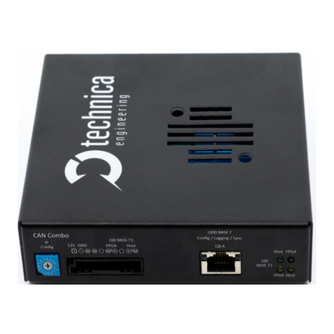
Technica Engineering CM CAN Combo User manual
Technica Engineering
Technica Engineering 1000Base-T1 SPY mini User manual
Technica Engineering
Technica Engineering TE-1437 User manual
Popular Control Unit manuals by other brands
Allmatic
Allmatic BIOS1 BRT Manual for installation

Mallory
Mallory FIRE STORM 69050S Hardware installation

Crosswater
Crosswater US-BL1000EV installation instructions
Allen-Bradley
Allen-Bradley ControlLogix 1756-DH485 user manual
NuAire
NuAire ES-LCD Installation & operating instructions
AMX
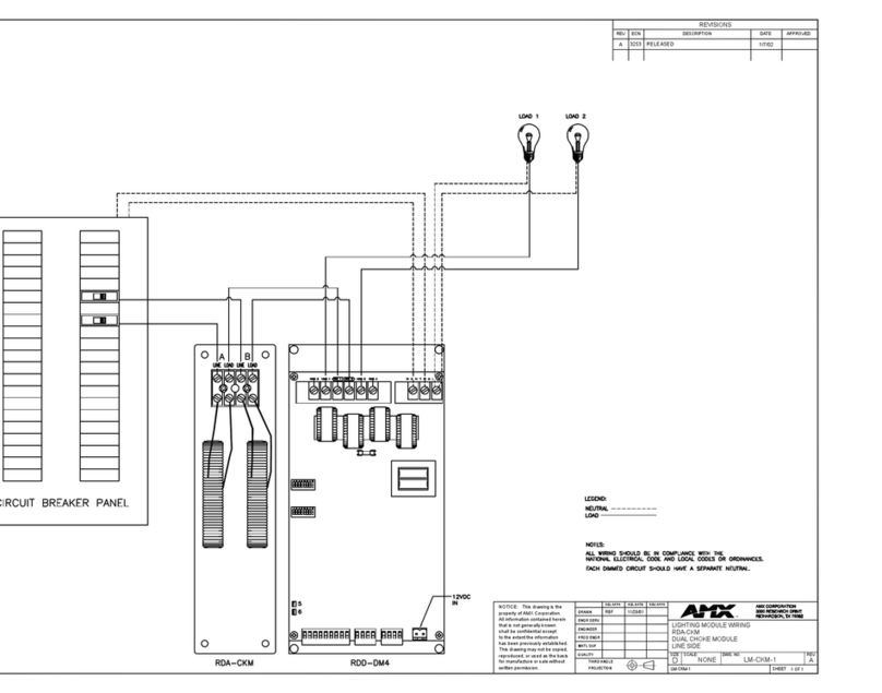
AMX RDA-CKM Wiring diagram


