manuals.online logo
Brands
  1. Home
  2. •
  3. Brands
  4. •
  5. Technics
  6. •
  7. Cassette Player
  8. •
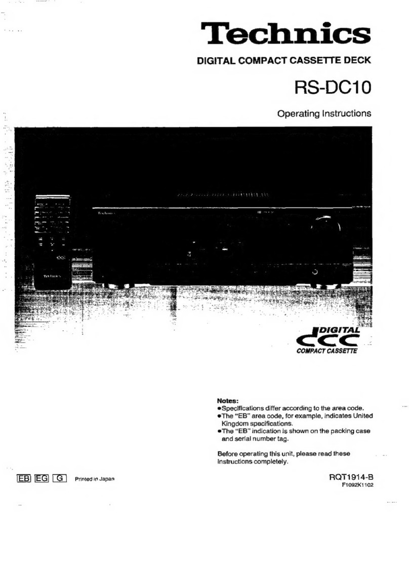
  9. Technics RS-X102 User manual

Technics RS-X102 User manual

Other Technics Cassette Player manuals
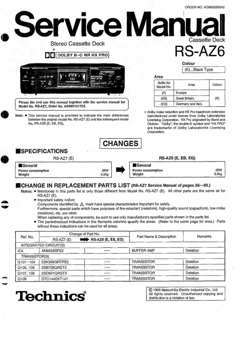
Technics RS-AZ6 User manual

Technics

Technics RS-AZ6 User manual

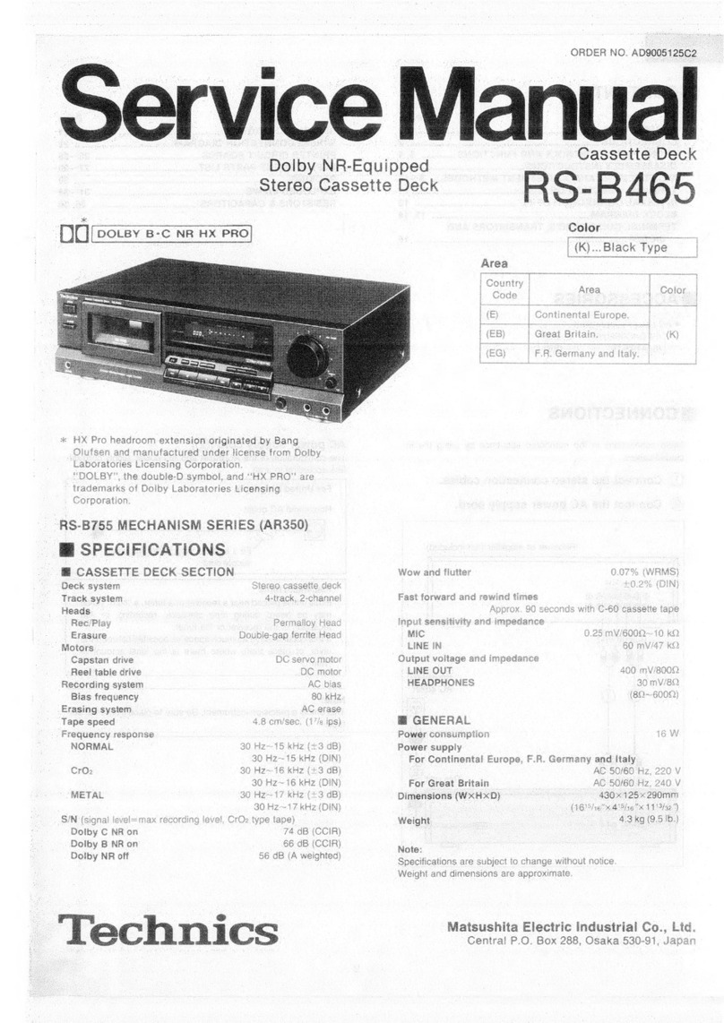
Technics RS-B465 User manual

Technics

Technics RS-B465 User manual

Technics RS-TR474 User manual

Technics

Technics RS-TR474 User manual

Technics RS-M04 User manual

Technics

Technics RS-M04 User manual

Technics RS-TR575 User manual

Technics

Technics RS-TR575 User manual

Technics RS-M235X User manual

Technics

Technics RS-M235X User manual

Technics RS-M228X User manual

Technics

Technics RS-M228X User manual

Technics RS-M250 User manual

Technics

Technics RS-M250 User manual

Technics RS-CH770 User manual

Technics

Technics RS-CH770 User manual

Technics RSTR155 - DUAL CASS RECORDER User manual

Technics

Technics RSTR155 - DUAL CASS RECORDER User manual

Technics RS-TR232 User manual

Technics

Technics RS-TR232 User manual

Technics RS-CA01 User manual

Technics

Technics RS-CA01 User manual

Technics RS-B605 User manual

Technics

Technics RS-B605 User manual

Technics RS-D200 User manual

Technics

Technics RS-D200 User manual

Technics RS-TR474 User manual

Technics

Technics RS-TR474 User manual

Technics RS-CH700 User manual

Technics

Technics RS-CH700 User manual

Technics RSTR272 - DUAL CASS. RECORDER User manual
Technics

Technics RSTR272 - DUAL CASS. RECORDER User manual

Technics RS-M226 User manual

Technics

Technics RS-M226 User manual

Technics RS-TR575 User manual

Technics

Technics RS-TR575 User manual

Technics RS-AZ7 User manual

Technics

Technics RS-AZ7 User manual

Technics RS-TR575 User manual

Technics

Technics RS-TR575 User manual

Technics RS-B555 User manual

Technics

Technics RS-B555 User manual

Technics RS-DV290EG User manual

Technics

Technics RS-DV290EG User manual

Technics RS-TR252 User manual

Technics

Technics RS-TR252 User manual

Popular Cassette Player manuals by other brands

Ahuja CPA-360 Operation manual

Ahuja

Ahuja CPA-360 Operation manual

Sony Pressman TCS-60DV Specifications

Sony

Sony Pressman TCS-60DV Specifications

Philips AQ6485/14 Product information

Philips

Philips AQ6485/14 Product information

Sony TCM-200DV - Cassette Recorder operating instructions

Sony

Sony TCM-200DV - Cassette Recorder operating instructions

Nakamichi BX-300 Service manual

Nakamichi

Nakamichi BX-300 Service manual

Panasonic RQ-E25V operating instructions

Panasonic

Panasonic RQ-E25V operating instructions

Aiwa TP-VS535 operating instructions

Aiwa

Aiwa TP-VS535 operating instructions

Yamaha MT8X Operation manual

Yamaha

Yamaha MT8X Operation manual

Sherwood Newcastle D-480 operating instructions

Sherwood

Sherwood Newcastle D-480 operating instructions

Manta MA408 user manual

Manta

Manta MA408 user manual

GPO W0162B user guide

GPO

GPO W0162B user guide

Marantz CP230 Service manual

Marantz

Marantz CP230 Service manual

Sony HST-471 Service manual

Sony

Sony HST-471 Service manual

Sharp JC-AV1 Operation manual

Sharp

Sharp JC-AV1 Operation manual

Pioneer CT-W103 Service manual

Pioneer

Pioneer CT-W103 Service manual

Sony CFS-B15 - Am/fm Stereo Cassette Recorder operating instructions

Sony

Sony CFS-B15 - Am/fm Stereo Cassette Recorder operating instructions

Sony WMFS220 - Portable Sports AM/FM Cassette... operating instructions

Sony

Sony WMFS220 - Portable Sports AM/FM Cassette... operating instructions

Aiwa HS-TA21 operating instructions

Aiwa

Aiwa HS-TA21 operating instructions

manuals.online logo
manuals.online logoBrands
  • About & Mission
  • Contact us
  • Privacy Policy
  • Terms and Conditions

Copyright 2025 Manuals.Online. All Rights Reserved.

ORDER
NO.
AD9103044C8
Service
Manual
Cassette
Deck
Dolby
NR-Equipped
S-X
0
Stereo
Double
Cassette
Deck
R
1
2
Color
(K)...
Black
Type
DiC
[etsy
system]
ick
Country
Code
Area
Continental
Europe.
Great
Britain.
F.R.
Germany
and
Italy.
(K)
Asia,
Latin
America,
Middle
Near
East
and
Africa.
Oceania.
MECHANISM
SERIES
(AR300)
SPECIFICATIONS
M@
CASSETTE
DECK
SECTION
Wow
and
flutter
0.1
%
(WRMS)
Fast
forward
and
rewind
times
Deck
system
Stereo
cassette
deck
Approx.
110
seconds
with
C-60
cassette
tape
Track
system
4-track,
2-channel
Input
sensitivity
and
Impedance
Heads
LINE
60
mV/47
kQ
(tape
deck
2)
rec/play
Permalloy
head
Output
voltage
and
impedance
erasing
Double-gap
ferrite
head
LINE
400
mV/800
Q
(tape
deck
1)
play
Permalloy
head
Motors
(tape
deck
2)
Capstan/reel
table
drive
§
DC
servo
motor
WM
GENERAL
(tape
deck
1)
Capstan/reel
table
drive
|©§
DC
servo
motor
Recording
system
AC
bias
Power
consumption
15
W
Bias
frequency
80
kHz
Dimensions
(W
x
H
x
D)
360
x
129
x
285
mm
Erasing
system
AC
erase
(14-3/16"
x
§-3/32”
x
11-7/32")
Tape
speeds
4.8
cm/sec.
(1-7/8
ips)
Weight
3.7
kg
(8.1
Ib.)
Frequency
response
(wio
Dolby
NR)
NORMAL
30
Hz~16
kHz
40
Hz~15
kHz
(DIN)
cro,
30
Hz~16
kHz
40
Hz~15
kHz
(DIN)
Note:
METAL
30
Hz~18
kHz
Specifications
are
subject
to
change
without
notice.
40
Hz~17
kHz
(DIN)
Weight
and
dimensions
are
approximate.
SIN
(signal
level
=
max
recording
level,
CrO.
type
tape)
*
Dolby
noise
reduction
manufactured
under
license
Dolby
B
NR
ON
66
dB
(CCIR)
from
Dolby
Laboratories
Licensing
Corporation.
Dolby
NR
OFF
56
dB
(A
weighted)
“Dolby”
and
the
double-D
symbol
are
trade
marks
of
Dolby
Laboratories
Licensing
Corporation.
Technics
RS-X102
|
Mi
CONTENTS
Page
ACCESSORIES.
..........-sssessssssctsesrsccsncssnssenssensonsensonensecsesnsseunerssees
2
INTERNAL
CONNECTION
OF
FL
.u......sccsssssssessessessssesnersseeee
CONNECTIONS
otaare
WIRING
CONNECTION
DIAGRAM.
LOCATION
OF
CONTROLS
........ccssesressesressesccrsnsreoesensseneons
3,4
TERMINAL
FUNCTION
OF
1C7S...........cssssssseecessoeseensoenee
DISASSEMBLY
INSTRUCTIONG..........ccccsscssssssssssseseneeseens
5~8
PACKING
bascccie.
rect
eocicatecish
eck
ee
ae
tise
cet
eee
duaataneel
«
INFORMATION
ON
POWER
SUPPLY
FIXTURE.................00+
9
REPLACEMENT
PARTS
LIST...
MEASUREMENTS
AND
ADJUSTMENTG...............
-
10~12
RESISTORS
&
CAPACITORG...........
BLOCK
DIAGRAM........scscccsssesssssssncsssnsecsesserserseneesssensneenens
13,
14
EXPLODED
VIEWS
(Cabinet
parts).
PRINTED
CIRCUIT
BOARDG...........-cssssssssssseseessesensrstees
15~18
REPLACEMENT
PARTS
LIST...........00000
SCHEMATIC
DIAGRAM
.........s:scssccsessssssersesseaseerenenensenees
19~23
EXPLODED
VIEWS
(Mechanica!
parts)..
TERMINAL
GUIDE
OF
IC’S,
TRANSISTORS
AND
REPLACEMENT
PARTS
LIST
............0+0000+
DIODES.
.........sscessssesnsersvsnnssssnsnsesssessensencesenennerenernenenseseneoss
23
Mi
ACCESSORIES
———"
3-core
flat
cable
L-type
cable
Stereo
connection
cables
(REX0346)
:
(SJP2257T)
:
(SJP2249-3)
Amplifier
Make
connections
in
the
numbered
sequence
by
using
the
included
cables.
Stereo
connection
cable
ON
ag
cunnent
OFF
7"
SENSOR
AC
OUTLET
ge
yy
©)
[ed
UNSWITCHED:
White
(L)
Red
(R)
=
SYSTEM
CONTROL
CONTROL
[1]
Connect
the
stereo
connection
cables.
[2]
Connect
the
L-type
cable.
[3]
Connect
the
flat
cable.
SYSTEM
CONTROL
OUT
This
terminal
is
used
to
connect
a
Technics
compact
disc
player
or
a
Technics
stereo
graphic
equalizer
with
the
“SYSTEM
CONTROL
IN”
terminal.
This
terminal
is
used
to
connect
a
Technics
muiti
com-
pact
disc
player
with
the
“CONTROL”
terminal.
RAO
Aw
Cassette
deck
SYSTEM
IN
QUT
(TO
CD)
INE
OU)
mn
Goose
SYSTEM
CONTROL
OUT}
(CONTROL
|
Rs-x102
Mi
LOCATION
OF
CONTROLS
AUTO
REVERSE
recone
marsax
DECK
2
Controls
common
to
both
tape
decks
Indicators
common
to
both
tape
decks
[4]
DECK
ON/OFF
switch
(DECK)
RC1
PLAY
<@
PLAY
RC2
[2]
Synchro-start
button
(SYNCHRO
START)
This
button
can
be
used
to
start
a
tape-to-tape
recording,
simultaneously
starting
tape
deck
1
(the
playback
deck)
and
tape
deck
2
(the
recording
deck).
[A]
Input
level
meter
During
playback,
this
meter
indicates
the
level
of
the
record-
ed
sound
source.
[3]
Tape-to-tape
recording
tape-speed
selector
During
recording,
it
indicates
the
level
being
recorded,
(TAPE
EDIT
SPEED)
adjusted
by
the
recording-level
control.
This
selector
can
be
used
to
select
the
recording
speed
when
a
tape-to-tape
recording
is
made.
Dolby
noise-reduction
indicator
(DOLBY
NR)
This
indicator
illuminates
when
the
Dolby
noise-reduction
[4]
Recording-level
contro!
(REC
LEVEL)
button
is
pressed.
This
control
can
be
used
to
regulate
the
recording
level
of
tape
deck
2.
Reverse-mode
indicators
(
=
,
c>
,
o>)
One
of
these
indicators
illuminates
to
show
which
of
the
reverse
modes
was
selected
by
the
reverse-mode
selector.
[5]
Reverse-mode
selector
(REVERSE
MODE)
This
selector
can
be
used
for
selection
of
the
reverse
mode
(for
either
playback
or
recording).
[D]
Edit-recording
indicators
(EDIT
MODE,
CD,
x1,
x2)
The
words
“EDIT
MODE”
and
“x1
(or
"x
2”)
indicator
will
[6]
Dolby
noise-reduction
button
(DOLBY
NR)
illuminate
when
a
tape-to-tape
recording
is
made.
This
button
is
used
to
reduce
the
“hissing”
noise
heard
from
The
words
“EDIT
MODE”
and
“CD”
indicator
will
illuminate
the
tape.
when
a
CD
edit-recording
is
made.
RS-X102
Tape
deck
1
STEREO
DOUBLE
CASSETTE
DECK
Act
mae
Tape
deck
2
CEB
die
ac2
okey
ne
eee}
Toe)
oo.
SE
Ec
Controls
applicable
to
tape
deck
1
and/or
2
[1]
Cassette
holder
[2]
Eject
button
(4
EJECT)
This
button
can
be
used
to
open
the
cassette
holder.
[3]
Pause
button
(If
PAUSE)
This
button
can
be
used
to
temporarily
stop
the
tape
playback
or
recording,
on
tape
deck
2
only.
[4]
Record
button
(REC)
This
button
can
be
used
to
change
tape
deck
2
to
the
recor-
ding
stand-by
mode.
[5]
Automatic-record-muting
button
(AUTO
REC
MUTE)
This
button
can
be
used
to
make
a
silent
interval
on
the
tape
during
recording,
on
tape
deck
2
only.
[6]
Fast-forward/cue,
rewind/review
buttons
(<<,
>)
These
buttons
are
used
to
advance
or
rewind
the
tape.
Dur-
ing
playback,
these
buttons
are
used
to
cue
or
review
while
listening
to
the
contents
at
high
speed.
Forward-side
playback
button
(>
PLAY)
This
button
can
be
used
to
start
the
playback
or
recording
of
side
‘‘A”’
of
the
cassette
in
tape
deck
2
only.
(The
tape
will
then
begin
moving
in
the
left-to-right
direction.)
Stop
button
(lf
STOP)
This
button
can
be
used
to
stop
tape
movement.
[9]
Reverse-side
playback
button
(<]
PLAY)
This
button
can
be
used
to
start
the
playback
or
recording
of
side
"B"
of
the
cassette
in
tape
deck
2
only.
(The
tape
will
then
begin
moving
in
the
right-to-left
direction.)
Tape
counter
reset
button
(RESET)
This
button
can
be
used
to
reset
the
tape
counter
indication
(for
tape
deck
2
only)
to
“000”.
Fast-forwardicue
button
(>>)
This
button
is
used
to
advance
the
tape.
During
playback
this
button
is
used
to
cue
the
contents
at
high
speed.
[12]
Rewind/review
button
(<<<)
This
button
is
used
to
rewind
the
tape.
During
playback
this
button
is
used
to
review
the
contents
at
high
speed.
Indicators
applicable
only
to
deck
1
or
2
RC.1
PLAY
DOLBY
NR
=
CD
OD
EDIT
MODE.
x1
CD
x2
[A]
Forward-side
indicator
(>)
This
indicator
illuminates
during
playback
or
recording
on
tape
deck
2
to
indicate
that
side
‘A’
of
the
tape
is
being
used.
Reverse-side
indicator
(<<)
This
indicator
illuminates
during
playback
or
recording
on
tape
deck
2
to
indicate
that
side
‘‘B"
of
the
tape
is
being
used.
Remote-control
indicator
(R.C.1/R.C.2)
This
indicator
illuminates
to
indicate
that
this
tape
deck
can
now
be
controlled
by
the
remote-control
transmitter
(included
with
tuner).
[D]
Playback
indicator
(PLAY)
When
this
indicator
illuminates
steadily,
it
indicates
that
this
tape
deck
is
in
the
playback
mode
or
the
recording
mode
(for
tape
deck
2
only).
When
it
flashes
continually,
this
is
an
indication
that
tape
deck
2
is
in
the
pause
mode
or
the
recording
stand-by
mode.
[E]
Recording
indicator
(EZ)
This
indicator
illuminates
to
indicate
that
tape
deck
2
is
in
the
recording
stand-by
mode
or
is
recording.
[F]
Tape
deck
2
counter
Indicates
the
amount
of
tape
movement.
RS-X102
Mi
DISASSEMBLY
INSTRUCTIONS
“ATTENTION
SERVICER”
Some
chassis
components
may
have
sharp
edges.
Be
careful
when
disassembling
and
servicing.
Ref.
No.
2
i
NO;
|
Removal
of
the
cabinet
Removal
of
the
front
panel
ass’y
|
Procedure
Procedure
«Remove
the
6
screws
(O~@).
Ref.
No.
3
Procedure
1-2-3
Removal
of
the
main
P.C.B.
Rear
panel
Front
panel
ass’y
2.
Remove
the
2
connectors
(CP1,
CP2).
3.
Remove
the
5
flat
cables
(CN3,
CN4,
CN5,
CN6,
CN8).
4.
Remove
the
front
panel
ass’y
in
the
direction
of
arrow.
How
to
remove
the
flat
cable
¢Pull
out
the
flat
cable
while
1.
Lift
the
connector.
pressing
the
connector.
2.
Pull
out
the
flat
cable.
(CN3,
CN5,
CN8)
(CN4,
CN6)
Pa
Flat
cable
5
My
Connector
,
Ole
at
Connector
2.
Remove
the
5
screws
(O~@).
Removal
of
the
mechanism
units
(DECK
1,
DECK
2)
Ref.
No.
4
Removal
of
the
FL
meter
P.C.B.
Procedure
1-2-5
Procedure
FL
meter
P.C.B.
Cassette
holder
(DECK
1)
Eject
button
(DECK
1)
Eject
button
(DECK
2)
1.
Remove
the
2
screws
(O,
@).
2.
Remove
the
FL
meter
P.C.B.
in
the
direction
of
arrow.
; ;
Cassette
holder
Mechanism
unit
(DECK
2)
r
Ref.
No.
6
Procedure
1-2—-4—5-6
Removal
of
the
mechanism
angle
@
Removal
of
the
mechanism
unit
(DECK
1)
1.
Press
the
eject
button
and
open
the
cassette
holder.
2.
Remove
the
4
screws
(@~®).
i
Removal
of
the
mechanism
unit
(DECK
2)
1.
Press
the
eject
button
and
open
the
cassette
holder.
2.
Remove
the
4
screws
(@~®).
Removal
of
the
eject
angle,
eject
buttons,
and
eject
lever
Procedure
ox
Eject
rod——____
:
2S
YA
Eject
lever
Eject
button
(DECK
1)
i.
4
©
Eject
button
(DECK
2)
3.
Pull
out the
claw
of
the
eject
4.
Turn
the
eject
lever
in
the
rod
in
the
direction
of
direction
of
arrow
@,
and
1.
Release
the
1
claw.
arrow
®,
remove
the
eject
remove
the
eject
lever
in
the
2.
Pull
out
the
eject
angle
in
the
buttons
and
the
eject
rod
in
direction
of
arrow
@.
direction
of
arrow
®.
the
direction
of
arrow
@.
—6-—
RS-X102
Removal
of
the
cassette
lid
Removal
of
the
cassette
holder
(DECK
1,
DECK
2)
(DECK
1,
DECK
2)
Procedure
1324-5
—6—7-8--9
Cassette
lid
(DECK
1)
Cassette
lid
©
Damper
gear
ass’y
(R)
(DECK
2)
e
Lift
the
cassette
lid
in
the
direction
of
arrow
@
and
remove
it
in
the
direction
of
arrow
©.
1.
Remove
the
2
screws
(O,
@).
2.
Remove
the
damper
gear
ass’y
(L)
and
damper
gear
Ref.
No.
:
ass’y
(R).
10
Removal
of
the
operation
P.C.B.
Procedure
1-24-56
78-910
Cassette
holder
(DECK
1)
SS
SN
Rec
level
knob
XS
;
&
x
SS
1.
Remove
the
rec
level
knob.
.
Remove
the
springs
in
the
direction
of
arrow
©.
.
Remove
the
ribs
in
the
direction
of
arrow
©.
.
Remove
the
cassette
holder
in
the
direction
of
arrow
@.
oe
©
3.
Release
the
14
claws.
|
2.
Remove
the
4
screws
(@~®@).
RS-X102
Ref.
No.
P
11
|
How
to
check
the
main
P.C.B.
|
0
Ps
Procedure
%
1-11
Rear
panel
Front
panel
ass’y
3.
Remove
the
4
screws
(O~®).
4.
Remove
the
front
panel
ass’y
in
the
direction
of
5.
Remove
the
bottom
board
ass’y.
arrow.
6.
Reinstall
the
front
panel
ass’y
to
the
main
P.C.B.
RS-X102
@
INFORMATION
ON
POWER
SUPPLY
FIXTURE
*
LOCATION
(Front
view)
(Rear
view)
Voltage
selector
(110/127
V/220
V/240
V)
Turntable
terminal
(DC
12V,
0.1A)
Spare
terminal
(AC
16V,
0.16A)
Tuner
terminal
(AC
9V,
0.6A)
Tape
Deck
terminal
(AC
11V,
1A
x2)
Power
switch
AC
cord
(AC
50/60
Hz
110/127/220/240V)
FL
Display
terminal
(AC
3V,
0.2A)
¢
SCHEMATIC
DIAGRAM
(Reference)
Spare
01
0.0
|
AC
16V
0.16A
Turntable
OC12V
O.1A
r
|
Fuse
|
F1(250V
1A)
|
L
eT
Fuse
F3
(125V
1A)
|
eerie
|
4
|
4
|
4
VOLTAGE
SELECTOR
Haare
|
Tuner
|
ACQV
0.68
BRN
f
'
Fuse
F4
(125V
2A)
to
SA
(AC
SOHz/60Hz
1¥0V/127V/220V
/240V)
{
Tape
Deck
t
fesse
ACI
1Ax2
{
|
Fuse
3K
Power
Supply
Fixture
Parts
No.
|
saris
©
(E,
EG)
af
as.....ccccccscsesseeeeeee
$ZZA1062C
u
!
*
(EB)
area
..
SZZA1063C|
|
y
FE
(125v
0A)
C(GN)
Blea
scrinccns
canst
chs
SZZA1064C|
|
ee
ea
©
(GO)
area.
ccecssesseesesseeeeees
SZZA1065C
1
eee
ad
\
FL
Display
!
GRY
AC3V
0.28
{
O
rar
eace
¢«
HOW
TO
CONNECT
Voltage
controller
Power
Supply
Fixture
MAIN
P.C.B.
(1)
AC
IN
Supply
the
same
voltage
as
indicated
on
the
©
voltage
selector
of
power
supply
Fixture.
RS-X102
|
MIMEASUREMENTS
AND
ADJUSTMENTS
Measurement
Condition
Rec.
level
control;
Maximum
¢
Dolby
NR
selector
switch;
Off
¢
Reverse-mode
selector
switch;
—_~
©
Make
sure
heads
are
clean
¢
Tape-to-tape-recording
tape-speed
selector;
X1
e
Make
sure
capstan
and
pressure
roller
are
clean
¢
Judgeable
room
temperature
20+5°C
(68+9°
F)
Measuring
instrument
¢
EVM
(Electronic
Voltmeter)
¢
ATT
(Attenuator)
*
Oscilloscope
e¢
DC
voltmeter
¢
Digital
frequency
counter
¢
Resistor
(600Q)
¢
AF
oscillator
Test
tape
¢
Head
azimuth
adjustment
(8kHz,
—20dB);
QZZCFM
¢
Playback
gain
adjustment
(315Hz,
0dB);
QZZCFM
*
Tape
speed
adjustment
(3kHz,
—
10dB);
QZZCWAT
©
Overall
frequency
response,
Overall
gain
adjustment
¢
Playback
frequency
response
(315Hz,
12.5kHz,
10kHz,
Normal
reference
blank
tape
;
QZZCRA
8kHz,
4kHz,
1kHz,
250Hz,
125Hz,
63Hz,
—20dB);
CrO,
reference
blank
tape;
QZZCRX
QZZCFM
Metal
reference
blank
tape;
QZZCRZ
e
Adjustment
Points
MAIN
PC.B.
(Leh)
(Roh)
mA
OVERALL
FREQUENCY
RESPONSE
ADJ.
DECK
2:
VR303(Lch}
{VR302
(Recht
PLAYBACK
GAIN
ADu.
DECK
I:
VR3(Lch
{VR4(Rch)}
TAPE
SPEED
ADJ.
DECK
2:
VR5(Lch)
{VRE(Rch)}
DECK
2
:vR902
(XI),
VR9OK
X2)
DECK
I:
VRSO3(X1}
vré
[][9](9][9]
VR302
vR903
[9]
[@]
[@]VR90!
vR902
VR301
4
vrs
|)
He
ERASE
CURRENT
ADv.
1c901
|
DECK
2:
vR30I
ERASE
CURRENT
MODE
TEST
POINT
ADJ.
TEST
POINT
(Soldered
Surface)
(DECK
2)
OVERALL
GAIN
ADu.
VR7
[@
DECK
2:
VR7(Lch)
{VR8(Rch)}