manuals.online logo
Brands
  1. Home
  2. •
  3. Brands
  4. •
  5. Technics
  6. •
  7. Cassette Player
  8. •
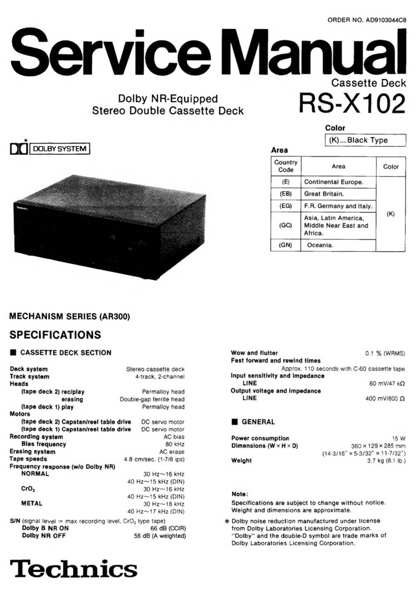
  9. Technics RS-X933 User manual

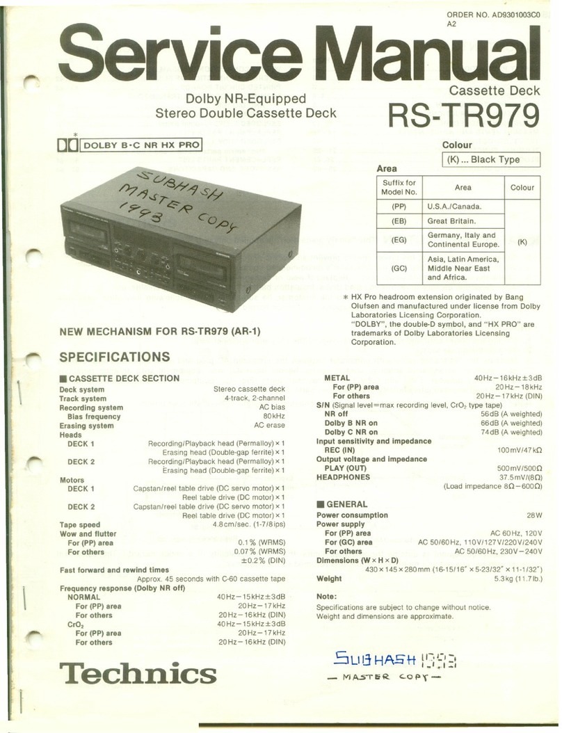
Technics RS-X933 User manual

Other Technics Cassette Player manuals

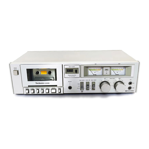
Technics RS-B10 User manual

Technics

Technics RS-B10 User manual

Technics RSTR272 - DUAL CASS. RECORDER User manual

Technics

Technics RSTR272 - DUAL CASS. RECORDER User manual

Technics RS-TR252 User manual

Technics

Technics RS-TR252 User manual

Technics RS-B205 User manual

Technics

Technics RS-B205 User manual

Technics RS-M7 User manual

Technics

Technics RS-M7 User manual

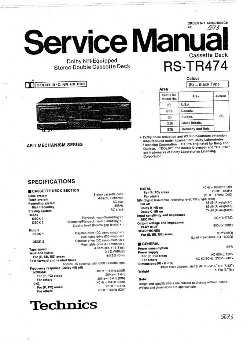
Technics RS-TR474 User manual

Technics

Technics RS-TR474 User manual

Technics RS-B755 User manual

Technics

Technics RS-B755 User manual

Technics RS-TR252 User manual

Technics

Technics RS-TR252 User manual

Technics RS-TR474 User manual

Technics

Technics RS-TR474 User manual

Technics RS-M226 User manual

Technics

Technics RS-M226 User manual

Technics RS-TR333 - SCHEMATICS User manual

Technics

Technics RS-TR333 - SCHEMATICS User manual

Technics RS-B465 User manual

Technics

Technics RS-B465 User manual

Technics RS-B14 User manual

Technics

Technics RS-B14 User manual

Technics RS-M226 User manual

Technics

Technics RS-M226 User manual

Technics RS-AZ6 User manual

Technics

Technics RS-AZ6 User manual

Technics RS-CA01 User manual

Technics

Technics RS-CA01 User manual

Technics RS-DV290EG User manual

Technics

Technics RS-DV290EG User manual

Technics RS-676US User manual

Technics

Technics RS-676US User manual

Technics RSTR272 - DUAL CASS. RECORDER User manual

Technics

Technics RSTR272 - DUAL CASS. RECORDER User manual

Technics RS-BX747 User manual

Technics

Technics RS-BX747 User manual

Technics RS-DC10 User manual

Technics

Technics RS-DC10 User manual

Technics RS-B655 User manual

Technics

Technics RS-B655 User manual

Technics RS-M250 User manual

Technics

Technics RS-M250 User manual

Technics RS-BX606 User manual

Technics

Technics RS-BX606 User manual

Popular Cassette Player manuals by other brands

Ahuja CPA-360 Operation manual

Ahuja

Ahuja CPA-360 Operation manual

Sony Pressman TCS-60DV Specifications

Sony

Sony Pressman TCS-60DV Specifications

Philips AQ6485/14 Product information

Philips

Philips AQ6485/14 Product information

Sony TCM-200DV - Cassette Recorder operating instructions

Sony

Sony TCM-200DV - Cassette Recorder operating instructions

Nakamichi BX-300 Service manual

Nakamichi

Nakamichi BX-300 Service manual

Panasonic RQ-E25V operating instructions

Panasonic

Panasonic RQ-E25V operating instructions

Aiwa TP-VS535 operating instructions

Aiwa

Aiwa TP-VS535 operating instructions

Yamaha MT8X Operation manual

Yamaha

Yamaha MT8X Operation manual

Sherwood Newcastle D-480 operating instructions

Sherwood

Sherwood Newcastle D-480 operating instructions

Manta MA408 user manual

Manta

Manta MA408 user manual

GPO W0162B user guide

GPO

GPO W0162B user guide

Marantz CP230 Service manual

Marantz

Marantz CP230 Service manual

Sony HST-471 Service manual

Sony

Sony HST-471 Service manual

Sharp JC-AV1 Operation manual

Sharp

Sharp JC-AV1 Operation manual

Pioneer CT-W103 Service manual

Pioneer

Pioneer CT-W103 Service manual

Sony CFS-B15 - Am/fm Stereo Cassette Recorder operating instructions

Sony

Sony CFS-B15 - Am/fm Stereo Cassette Recorder operating instructions

Sony WMFS220 - Portable Sports AM/FM Cassette... operating instructions

Sony

Sony WMFS220 - Portable Sports AM/FM Cassette... operating instructions

Aiwa HS-TA21 operating instructions

Aiwa

Aiwa HS-TA21 operating instructions

manuals.online logo
manuals.online logoBrands
  • About & Mission
  • Contact us
  • Privacy Policy
  • Terms and Conditions

Copyright 2025 Manuals.Online. All Rights Reserved.

Dolby
NR-Equipped
Stereo
Double
Cassette
Deck
DC)
[eousy
-c
wa]
SPECIFICATIONS
Ml
CASSETTE
DECK
SECTION
Deck
system
Stereo
cassette
deck
Track
system
4-track,
2-channel
Heads
(tape
deck
A)
Rec/play
Permalloy
head
Erasing
Double-gap
ferrite
head
(tape
deck
B)
play
Permailoy
head
Motors
(tape
deck
A)
Capstanireel
table
drive
©
DC
servo
motor
(tape
deck
B)
Capstan/reel
table
drive
OC
servo
motor
Recording
system
AC
bias
Bias
frequency
80
kHz
Erasing
system
AC
erase
Tape
speed
4.8
cmisec.
(1-7/8
ips)
Frequency
response
(w/o
Dolby
NR)
NORMAL
30
Hz~16
kHz
40
Hz~15
kHz
(DIN)
cro,
30
Hz~16
kHz
40
Hz~15
kHz
(DIN)
METAL
30
Hz~18
kHz
40
Hz~17
kHz
(DIN)
SIN
(signal
fevel
=
max
recording
level,
CrO,
type
tape)
Dolby
C
NR
on
74
dB
(CCIR)
Dolby
B
NR
on
66
dB
(CCIR)
Dolby
NR
off
56
dB
(A
weighted)
Technics
Service
Manual
ORDER
NO.
AD8904094C8
Cassette
Deck
RS-X933
Color
(K)...
Black
Type
Area
Country
(E/E5)
|
Continental
Europe.
|
tk)
|
(EB)
|
Great
Britain.
|
(kK)
(K)
(K)
foo
[esas
|
(West
Germany).
|
(eo)
|
Thi
")
K
(GC)
Third
Region
|
Kk)
|
Wow
and
flutter
Fast
forward
and
rewind
times
Approx.
110
seconds
with
C-60
cassette
tape
Input
sensitivity
and
impedance
0.1
%
(WRMS)
LINE
;
60
mV/47
kQ
Output
voltage
and
impedance
LINE
400
mV/800
Q
M@
GENERAL
Power
consumption
15
W
Power
supply
AC
50/60
Hz
220V
((EG)
area
only)
Dimensions
(W
x
H
x
D)
360
x
129
x
270
mm
(14-3/16""
x
5-2/32”'
x
10-5/8’’)
Weight
For
[EG]
area.
4.
Okg
(8.8
Ib.)
For
others.
3,
5kg
(7.7
|b.)
Note:
Specifications
are
subject
to
change
without
notice.
Weight
and
dimensions
are
approximate.
*
Dolby
noise
reduction
manufactured
under
license
from
Dolby
Laboratories
Licensing
Corporation.
“Dolby”
and
the
double-D
symbol
are
trade
marks
of
Dolby
Laboratories
Licensing
Corporation.
Matsushita
Electric
Industrial
Co.,
Ltd.
Central
P.O.
Box
288,
Osaka
53(-91,
Japan
RS-X933
@
CONTENTS
*Location
of
Controls...........
Hot
to
Connection
...............
¢
Disassembly
Instructions
¢Information
on
Power
Supply
Jig
...........:::secseeees
9
Measurement
and
Adjustment
Methodes.....
10~12
¢Terminal
Function
of
IC’s
¢
Printed
Circuit
Boards.................0
Schematic
Diagram............ccccccccesesssesesseeeees
li
LOCATION
OF
CONTROLS
1
2) [3
[1]
Power
on/off
switch
(POWER)
sat
ceaLacascecconsceecssaces
ssssseeeeees
(E,
E5,
GC,
GN)
areas.
Power
on/stanby
(!)
switch
(POWER)
dunce
cacessadsdesassneuenieesdcndadcecucteaveaapavavesaceaaue
(EG)
area.
Deck
on/off
switch
(DECK)................
(EB)
area.
[2]
Timer
switch
({)
TIMER)
This
switch
can
be
used
to
automatically
begin
a
tape
recor-
ding
or
tape
playback
at
a
certain
time,
selected
by
an
op-
tional
timer.
[3]Reverse-mode
selector
(REVERSE
MODE)
This
selector
can
be
used
for
selection
of
the
reverse
mode
(for
either
playback
or
recording).
[4]
Tape
counter
(DECK
A
COUNTER)
Indicates
the
amount
of
tape
movement.
[5]
Tape
counter
reset
button
(RESET)
This
button
can
be
used
to
reset
the
tape
counter
indication
to
“O00”.
Page
¢
Terminal
Guide
of
IC’s,
Transistors
and
Diodes..............cccccscsssssseseees
25
©
Block
Diagram.
...........ccccssscsessssesseseeessenssesensaees
26,
27
Wiring
Connection
Diagram
..............cccccsssssseeeee
28
Resistors
&
Capacitors.............cccsessseserenreees
29~32
Replacement
Parts
List
(Electrical
Parts).....
33~35
Mechanical
Parts
Location
(DECK
A).............
36,
37
e
Replacement
Parts
List
(Mechanical
Parts)
..............ccccsscessssssersees
Mechanical
Parts
Location
(DECK
B)
is
Cabinet
Parts
Location.
............:.ccseccsessseenseees
[6]Input
level
meter
(PEAK
LEVEL)
During
tape
playback,
this
meter
indicates
the
level
of
the
recorded
sound
source.
During
recording,
it
indicates
the
level
to
which
the
record-
ing-level
control
has
been
adjusted.
Dolby
noise-reduction
buttons/indicators
(DOLBY
NR)
These
buttons
can
be
used
to
reduce
the
hiss
noise
that
is
characteristic
of
tape.
This
unit
is
provided
with
both
the
B-type
and
C-type
noise-reduction
systems.
Edit-recording
tape-speed
buttons/
indicators
(EDIT
SPEED)
These
buttons
can
be
used
to
select
the
recording
speed
when
a
tape-to-tape
recording
is
made.
[9]Synchro-start
button
(SYNCHRO
START)
This
button
can
be
used
to
start
a
tape-to-tape
recording,
simultaneously
starting
tape
deck
B
(the
playback
deck)
and
tape
deck
A
(the
recording
deck).
[10]
Recording-level
control
(REC
LEVEL)
This
control
can
be
used
to
regulate
the
recording
level
of
tape
deck
A.
Cassette
Deck
ORDER
NO.
AD8904094C8-A
4
RS-X933
DEUTSCH
MESSUNGEN
UND
EINSTELL
METHODEN
MeBinstrumente
¢
Elektronisches
Voltmeter
(EVM)
*
Oszilloskop
°
Digitaler
Frequenzmesser
¢
Audiofrequenz-Oszillator
Tonkopf-Azimuteinstellung
(Deck
A/B)
1.
Spielen
Sie
auf
dem
Testband
(QZZCFM)
den
Teil
fir
die
Azimuteinstellung
(8kHz,
—20dB)
ab.
Drehen
Sie
die
Azimuteinstellschraube
so
lange,
bis
die
Abgaben
des
L-K
und
R-K
den
Hodchstwert
erreichen,
und
die
Lissajosscghe
wellenfigur
sich,
wie
abgebildet,
0
Grad
nahert.
Anmerkung:
When
L-K
und
R-K
nicht
auf
demselben
Punkt
ihren
Hochstwert
erreichen,
stellen
Sie
beide
Kandle
auf
den
jeweiligen
Héchstwert
und
gleichen
dann
aus.
.
Nehmen
Sie
denselben
Ejinstellvorgang
in
der
Wiedergabestellung
vor.
Bandgeschwindigkeits-einstellung
(Deck
A/B)
Normale
Geschwindigkeit
.
Den
Wahlschalter
fiir
Editier-Bandgeschwindigkeit
auf
“x1”
stellen.
.
Den
mittleren
Teil
des
Prifbandes
(QZZCWAT)
wiedergeben.
.
Deck
B=
VR902
und
Deck
A=VR903
so
einstellen,
daB
Einstellung
der
Wiedergabeverstarkungsregelung
(Deck
A/B)
1.
Spielen
Sie
auf
dem
Testband
(QZZCFM)
den
Teil
fir
die
Einstellung
der
Verstarkungsregelung
(315Hz,
0dB)
ab.
Wiedergabefrequenzaang
(Deck
A/B)
1.
Spielen
Sie
auf
dem
Testband
(QZZCFM)
den
Teil
far
den
Frequenzgang
(315Hz,
12,5kHz~63Hz,
—20dB)
ab.
¢
Dampfungswiderstand
¢
Gleichstrom-Voltmeter
e
Widerstand
(600Q)
Priifung
des
Pegelunterschiedes
bei
Vorwarts-
und
Riickwartsdrehung
3.
Den
Abschnitt
fur
Verstarkungseinstellung
(315Hz,
0dB)
des
Prifbandes
(QZZCFM)
wiedergeben
und
sicherstellen,
daB
der
Pegelunterschied
bei
Vorwarts-
und
Rackw&rtsdrehung
kleiner
alS
1B
ist.
.
Nach
der
Einstellung
Schrauben-Sicherungsmitte!
an
die
Azimuth-Einstellschraube
geben.
Hohe
Geschwindigketi
4.
Den
Wahlschalter
fir
Editier-Bandgeschwindigkeit
auf
“x2”
stellen
und den
Prifmoduspunkt
und
GND
verbinden.
.
Den
mittleren
Teil
des
Prufbandes
(QZZCWAT)
wiedergeben.
.
Deck
B=
VR901
so
einstellen,
daB
der
Ausgang
dem
Sollwert
entspricht.
.
Stellen
Sie
VR3
(L-K)
[[VR4
(R-K)]]
far
Deck
B
uon
VR5
(L-K)
[[VR6
(R-K)]]
far
Deck
A
so
ein,
daB
die
Abgabe
den
Normwert
erfillt.
.
Achten
Sie
darauf,
daB
der
Frequenzgang
fir
beide
Kanale
(L-K,
R-K)
in
dem
in
Abb.
6
gezeigten
Bereich
liegt.
Léschstromeinstellung
(Deck
A)
1.
Die
leere
Metaliband-Prifkassette
(QZZCRZ)
einsetzen
und
das
Gerat
auf
Aufnmahmepause
schalten.
.
VR301
so
einstellen,
daB
der
Ausgang
zwischen
TP3
und
GND
dem
Sollwert
entspricht.
Gesamtfrequenzgang
(Deck
A)
.
Legen
Sie
das
normale
Leertestband
(QZZCRA)
ein
und
stelien
das
Gerat
auf
Aufnahme-/Pause-Betrieb.
.
Geben
Sie
ber
einen
Lautstarkeregler
ein
Bezugseingabesignal
(1kHz,
—
24dB)
ein.
.
Stellen
Sie
das
Signal
auf
20dB
und
justieren
die
Frequenz
von
50Hz~10kHz.
.
Nehmen
Sie
das
Wobbelsignal
auf.
.
Geben
Sie
das
aufgenommene
Signal
wieder
und
achten
darauf,
daB
dieses
sich
im
Vergleich
zur
Bazugsfrequenz
(1kHz)
in
dem
in
Abb.
8
aufgezeichneten
Bereich
befindet.
Einstellung
der
Gesamtverstarkungsregelung
(Deck
A)
.
Legen
Sie
das
normale
Leertestband
(QZZCRA)
ein
und
stellen
das
Gerat
auf
Aufnahme-/Betrieb.
.
Legen
Sie
ein
Bezugseingabesignal
(1kHz,
—24dB)
an.
Stellen
Sie
das
Ausgangssignal
auf
einen
Pegel
von
0.4V
ein.
.
Nehmen
Sie
das
Eingabesignal
auf.
.
Sollte
das
Signal
nicht
im
Normbereich
liegen,
justieren
Sie
VR303
(L-K)
und
VR302
(R-K),
so
da®B
der
Frequenz-
pegel
mit
der
Norm
Ubereinstimmt.
.
Wiederholen
Sie
die
Schritte
2~6
und
verwender
das
CrO
2
Band
(QZZCRX)
und
das
Metallband
(QZZCRZ).
Der
Frequenzbereich
wird
auf
12.5kHz
(50Hz2z~12.5kHz)
angehoben.
.
Achten
Sie
darauf,
da®
sich
der
Frequenzpegel
in
dem
in
4,
Abb.
9
aufgezeigten
Bereich
befindet.
Geben
Sie
das
in
Schritt
3
oben
aufgenommene
Signal
wieder
und
achten
Sie
darauf,
daB
das
Ausgangssignal
mit
dem
Normwert
Ubereinstimmt.
.
Sollte
der
Wert
nicht
innerhalb
der
Norm
liegen,
justieren
Sie
VR7
(L-K)
und
VR8
(R-K).
.
Wiederholen
Sie
die
Schritte
2~5
von
oben
so
lange,
bis
das
Ausgangssignal
im
Normbereich
liegt.
RS-X933
FRANGAIS
METHODES
DES
MEASURES
ET
REGLAGES
Appareils
de
mesurage
e
Voitmétre
électronique
*
Oscilloscope
¢
Compteur
de
fréquence
numérique
¢
Oscillateur
de
fréquence
audio
Reglage
Azimutal
de
la
tete
(Platine
A/B)
1.
Faire
jouer
la
portion
du
réglage
de
l’azimuth
(8kHz,
—
20dB)
de
la
bande
d’essai
(QZZCFM).
Ajuster
ta
vis
de
ta
mise
au
point
azimutale
jusqu’a
de
que
les
sorties
du
canal
de
gauche
et
du
canal
de
droite
soient
maximisées
et
que
la
forme
d’onde
de
Lissajous,
comme
il
est
iflustré,
approche
de
0
degré.
Nota:
Si
le
canal
de
gauche
et
canal
de
droite
ne
sont
pas
maximisés
au
méme
point, régler
le
point
ou
les
niveaux
de
chaque
canal
sont
maximiséset
égaux.
2.
Effectuer
le
méme
r&e
19
mglage
sur
le
mode
d’audition.
°
A.T.T.
(Atténuateur)
©
Voltmétre
a
C.C.
e
Résistance
(600Q)
Vérification
de
la
difference
de
niveau
pour
les
deux
sens
de
rotation
3.
Introduire
une
bande
métal
vierge
prévue
pour
les
essais
(QZZCPZ)
et
vérifier
que
la
différence
de
niveau
pour
lés
déux
sens
de
rotation
est
inférieure
a
1dB.
4.
Aprés
cela,
mettre
une
goutte
de
vernis
de
blocage
sur
la
vis
de
régiage
de
!’azimut.
Réglage
de
la
vitesse
de
défilement
Vitesse
(Platine
A/B)
normal
.
Placer
le
sélecteur
de
vitesse
d’édition
sur
la
position
“xT”,
.
Lire
la
partie
centrale
de
la
bande
d’essai
(QZZCWAT).
.
Régler
VR902
pour
la
platine
B
et
VR901
pour
la
platine
A
de
maniére
que
la
sortie
ait
la
valeur
standard.
Reglage
de
L’amplification
de
Lecture
(Platine
A/B)
1.
Faire
jouer
la
partie
réglée
de
l’'amplification
(315
Hz,
0dB)
de
la
bande
d’essai
(QZZCFM).
Reponse
en
Frequence
de
la
Lecture
(Platine
A/B)
1.
Faier
jouer
la
partie
de
la
réponse
en
fréquence
(315
Hz,
12.5kHz,
—63Hz,
—20dB)
de
la
bande
d’essai
(QZZCFM).
Grande
vitesse
4.
Placer
le
sélecteur
de
vitesse
d’édition
sur
la
position
“x2”
et
relier
le
point
de
test
et
la
masse
(GND).
5.
Lire
la
partie
centrale
de
la
band
d’essai
(QZZCWAT).
6.
Régler
VR901
pour
la
platine
B
de
maniére
que
la
sortie
ait
la
valeur
standard.
2.
Régler
ia
platine
B:
VR3
(canal
de
gauche)
[[VR4
(canal
de
droite)]}]
et
la
platine
A:
VR5
(canal
de
gauche)
[[VR6
(canal
de
droite)]]
de
telle
sorte
que
la
sortie
soit
en
dega
de
la
valeur
standard.
2.
S’assurer
que
la
réponse
en
fréquence
soit
en
dega
de
la
plage
montrée
dans
Ia
Fig.
6,
a
la
fois
pour
le
canal
de
gauche
et
le
canal
de
droite.
FRANCAIS
FRANCAIS
RS-X933
Réglage
du
courant
d’effacement
(Platine
A)
1.
Introduire
une
bande
métal
vierge
prévue
pour
les
essais
(QZZCRZ)
et
régier
l'appareil
en
mode
de
pause
d’enregistrement.
Reponse
en
Frequence
Totale
(Platine
A)
.
Introduire
la
bande
d’essai
vierge
normate
(QZZCRA)
et
régier
l’appareil
sur
le
mode
d’intermission
d’un
disque.
.
Appliquer
un
signal
d’entrée
de
référence
(1kHz,
—
24dB)
par
l’intermédiaire
d’un
atténuateur.
.
Diminuer
te
signal
de
20dB
et
régler
la
fréquence
de
50Hz~10kHz.
.
Enregistrer
le
balayage
de
fréquence.
.
Faire
jouer
le
signal
enregistré
et
s’assurer
qu’i!
soit
en
dega
de
la
plage
montrée
a
la
Fig.
8
en
comparaison
a
la
fréquence
de
référence
(1
kHz).
Reglage
de
L’amplification
Totale
(Platine
A)
.
Introduire
la
bande
d’essai
vierge
normale
(QZZCRA)
et
régler
l'appareil
sur
le
mode
d’intermission
d’un
disque.
.
Appliquer
un
signal
d’entrée
de
référence
(1kHz,
—24dB).
Diminuer
la
sortie
de
telle
sorte
que
son
niveau
devienne
de
0.4V.
.
Enregistrer
ce
signal
d’entrée.
.
Régler
VR301
de
maniére
que
la
sortie
entre
TP3
et
GND
ait
la
valeur
standard.
.
Sil
n’est
pas
en
dega
de
la
plage
standard,
régler
VR303
(canal
de
gquche)
et
VR302
(canal
de
droite)
de
telle
sorte
que
le
niveau
de
fréquence
soit
en
dega
de
!a
plage
standard.
.
Répéter
les
étapes
2~6
ci-dessus
en
utilisant
la
band
CrO,
(QZZCRX)
et
la
bande
métallisée
(QZZCRX)
en
augmentant
la
plage
de
fréquence
a
12.5kHz
(50Hz~12.5kHz).
.
S’assurer
que
le
niveau
soit
en
dega
de
la
plage
montrée
a
la
Fig.
9.
.
Faire
jouer
le
signal
enregistré
a
l’étape
3
ci-dessus,
et
s’assurer
que
la
sortie
en
dega
de
la
valeur
standard.
.
Si
elle
n’est
pas
en
dega
de
la
valeur
standard,
régler
VR7
(canal
de
gauche)
et
VR8
(canal
de
droite).
.
Répéter
les
étapes
2~5
ci-dessus
jusqu’a
ce
que
la
sortie
soit
en
dega
de
la
valeur
standard.
Ajuste
de
!a
Corriente
de
Borrado
(Platina
A)
ESPANOL
[METODOS
DE
AJUSTE
Y
MEDIDA
|
.
Regule
VR301
de
modo
que
la
salida
entre
TP3
y
GND
esté
dento
de
los
valores
estandares.
1.
Inserte
la
cinta
de
prueba
metalica
en
blanco
(QZZCRZ)
y
ponga
el
aparato
en
la
modalidad
de
pausa
de
grabacién.
Respuesta
de
Frecuencia
Total
(Platina
A)
Instrumento
de
medicién
*
EVM
(Voltimetro
electrénico)
¢
Osciloscopio
¢
Frecuencimetro
digital
¢
ATT
(Atenuador)
¢
Voltimetro
CC
e
Resistor
(600Q)
.
Si
no
esta
dentro
de
la
gama
de
frecuencia,
ajustar
VR303
(CH-I)
y
VR302
(CH-D)
de
manera
que
el
nivel
de
.
Poner
una
cinta
virgen
normal
(QZZCRA)
y
poner
la
unidad
en
la
modalidad
de
Pausa
de
Grabacién.
¢
Oscilador
AF
Ajuste
Azimutal
de
Cabeza
(Platina
A/B)
1.
Reproducir
la
porcién
de
ajuste
azimutal
(8kHz,
—20dB)
de
la
cinta
de
prueba
(QZZCFM).
Variar
el
tornillo
de
ajuste
azimutal
hasta
que
las
salidas
del
CH-1
y
CH-D
se
maximicen
y
forma
de
onda
de
lissajous,
como
ilustrado,
se
acerque
a
grado
0.
Nota:
Si
CH-I
y
CH-D
no
son
maximizados
en
el
mismo
punto,
ajustar
al
punto
donde
los
niveles
de
cada
canal
sean
maximizados
e
igualados.
.
Efectuar
el
mismo
ajuste
en
la
modalidad
de
reproduccién.
Ajuste
de
la
Velocidad
de
la
Cinta
(Platina
A/B)
Velocidad
normal
.
Lleve
a
“x1”
el
selector
de
la
velocidad
de
la
cinta
de
edicién.
.
Reproduzca
la
seccién
central
de
la
cinta
de
prueba
(QZZCWAT).
.
Ajuste
la
platina
B=
VR902
y
la
platina
A=
VR903
de
modo
que
la
salida
quede
comprendida
dentro
de
los
valores
estandares.
Ajuste
de
Ganancia
de
Reproduccion
(Platina
A/B)
1.
Reproducir
la
porcién
ajustada
de
ganancia
(315
Hz,
0dB)
de
la
cinta
de
prueba
(QZZCFM).
Comprobacién
de
la
diferencia
de
nivel
de
giro
hacia
adelante
y
hacia
atras
3.
Reproduzca
la
parte
del
adjuste
de
ganancia
(315Hz,
OdB)
de
la
cinta
de
prueba
(QZZCFM)
y
juego
asegurese
de
que
la
diferencia
de
nivel
de
giro
hacia
adelante
y
hacia
atras
sea
menor
que
1dB.
.
Después
del
ajustc,
aplique
pintura
de
fijacién
al
tornillo
de
ajuste
del
azimut.
Alta
velocidad
4.
Lleve
a
“x2”
el
selector
de
la
velocidad
de
la
cinta
de
edicién
y
conecte
GND
y
el
punto
de
la
modalidad
de
prueba.
.
Reproduzca
la
seccién
central
de
la
cinta
de
prueba
(QZZCWAT).
.
Ajuste
la
platina
B=
VR901
de
modo
que
la
salida
quede
comprendida
dentro
de
los
valores
estandares.
.
Ajustar
la
Platina
B:
VR3
(CH-I)
[[VR4
(CH-D)]]
y
la
Platina
A:
VR5
(CH-I)
[[VR6
(CH-Dj]
de
manera
que
la
salida
esté
dentro
del
valor
estandar.
Respuesta
de
Frecuencia
de
Reproduccion
(Platina
A/B)
2.
1.
Reproducir
la
parte
de
respuesta
de
frecuencia
de
reproducci6n
(315
Hz,
12.5kHz~63
Hz,
—20dB)
de
la
cinta
de
prueba
(QZZCFM).
Asegurarse
de
que
la
respuesta
de
frecuencia
esté
dentro
de
la
gama
mostrada
en
la
Fig.
6
para
ambos
CH-!
y
CH-D.
.
Aplicar
la
sefial
de
entrada
de
referencia
(1kHz,
—24dB)
a
través
de
un
atenuador.
.
Atenuar
la
sefial
por
20dB
y
ajustar
la
frecuencia
de
50H2~10kHz.
.
Grabar
el
barrido
de
frecuencia.
.
Reproducir
la
sefial
grabada
y
asegurarse
de
que
esté
dentro
de
la
gama
mostrada
en
la
Fig.
8
en
comparaci6n
con
la
frecuencia
de
referencia
(1kHz).
Ajuste
de
Ganancla
Total
(Platina
A)
.
Insertar
la
cinta
de
prueba
en
blance
normal
(QZZCRA)
y
poner
la
unidad
en
modalidad
de
pausa
de
Grabacion.
.
Aplicar
la
sefial
de
entrada
de
referencia
(1kHz,
—24dB).
Atenuar
la
salida
de
manera
que
su
nivel
se
haga
0.4V.
.
Grabar
la
sefial
de
entrada.
frecuencia
esté
dentro
de
la
gama
estandar.
.
Repetir
los
pasos
2~6
de
arriba
utilizando
la
cinta
CrOz
(QZZCRX)
y
la
cinta
metalica
(QZZCRZ)
incrementando
la
gama
de
frecuencia
a
12.5kHz
(50H2~12.5kHz).
.
Asegurarse
de
que
el
nivel
est&e
19mdentro
de
la
gama
mostrada
en
la
Fig.
9.
.
Reproducir
la
sefial
grabada
en
el
paso
3
de
arriba
y
asegurarse
de
que
la
salide
esté
dentro
del
valor
estandar.
.
Sino
esta
dentro
del
valor
estandar,
ajustar
VR7
(CH-I)
y
VR8
(CH-D).
.
Repetir
el
paso
2~5
de
arriba
hasta
que
la
salida
esté
dentro
del
valor
estandar.
Printed
in
Japan
H890406310
YY/TN
10}
[14}
|
8)
[12)13)1
[1]Cassette
holder
[2]Remote-control
indicator
(REMOTE
CONTROL)
This
indicator
illuminates
to
indicate
that
this
tape
deck
can
now
be
controlled
by
the
remote-control
transmitter.
[3]
Reverse-side
indicator
(<)
This
indicator
illuminates,
during
playback
or
recording
of
tape
deck
A,
to
indicate
that
side
‘‘B”
of
the
tape
is
being
us-
ed.
[4]
Forward-side
indicator
(>)
This
indicator
illuminates,
during
playback
or
recording
of
tape
deck
A,
to
indicate
that
side
“A”
of
the
tape
is
being
us-
ed.
[5]
Playback
indicator
(PLAY)
When
this
indicator
illuminates
steadily,
it
indicates
that
this
tape
deck
is
in
the
playback
mode
or
the
recording
mode.
(for
tape
deck
A
only)
When
it
flashes
continually,
this
is
an
indication
that
the
tape
deck
A
is
in
the
pause
mode
or
the
recording
stand-by
mode.
[6]
Recording
indicator
(REC)
This
indicator
illuminates
to
indicate
that
the
tape
deck
A
is
in
the
recording
stand-by
mode
or
is
recording.
Eject
button
(4
/EJECT)
This
button
can
be
used
to
open
the
cassette
holder.
RS-X933
8;
{9}
(10) [11]
(8
[8]
Fast-forwardicue,
rewind/review
buttons
(<<>P>)
These
buttons
are
used
to
advance
or
rewind
the
tape.
Dur-
ing
playback
these
buttons
are
used
to
cue
or
review
while
listening
to
the
contents
at
high
speed.
[9]Reverse-side
playback
button
(</PLAY)
This
button
can
be
used
to
start
the
playback
or
recording
(of
deck
A
only)
of
side
‘“‘B”
of
the
cassette
in
this
tape
deck.
(The
tape
will
then
begin
moving
in
the
right-to-left
direction.)
Stop
button
(M/STOP)
This
button
can
be
used
to
stop
tape
movement.
[11]
Forward-side
playback
button
(b>/PLAY)
This
button
can
be
used
to
start
the
playback
or
recording
(of
deck
A
only)
of
side
“A”
of
the
cassette
in
this
tape
deck.
(The
tape
will
then
begin
moving
in
the
left-to-right
direction.)
[12]
Pause
button
(#8
PAUSE)
This
button
can
be
used
to
temporarily
stop
the
tape
playback
or
recording
of
deck
A
only.
[13]
Automatic-record-muting
button
(QO
AUTO
REC
MUTE)
This
button
can
be
used
to
make
(during
recording)
a
silent
interval
on
the
tape.
[14]
Record
button
(@
REC)
This
button
can
be
used
to
change
the
tape
deck
A
to
the
recording
stand-by
mode.
RS-X933
Mi
HOW
TO
CONNECTION
Turntable
REMOTE/
syncurorecc
§=—s(€“<S<sé‘ité‘é‘*é«sK
Rt
incl)
Tuner
(not
included)
RH
OMHURY
AOR
Y
goed
n
a
REmoTE
contro.
Graphic
INPUT
OUTPUT
equalizer
©)
‘0
(not
included)
@
“GND?”
terminal
of
the
amplifier
This
terminal
is
for
use
with
a
turntable
which
has
a
ground
wire.
@
“EXT”
terminals
of
the
amplifier
When
these
terminals
are
not
in
use,
be
INPUT
sure
to
insert
the
shorting
pins
(included).
OUTPUT
Shorting
pins
Connection
diagrams
shown
are
for
connections
to
a
Technics
hi-fi
component
system.
Make
connections
in
the
numbered
sequential
order.
[1]Connect
the
stereo
connection
cables
(included
with
the
turntable,
tuner,
graphic
equalizer,
compact
disc
player
and
cassette
tape
deck).
[2]Connect
the
L-type
cables
(included
with
the
turntable,
compact
disc
player,
graphic
equalizer
and
cassette
tape
deck).
Note:
Connect
the
L-type
cables
included
with
a
compact
disc
player
as
illustrated
below
in
either
case:
eWhen
a
graphic
equalizer
does
not
have
the
remote
control
terminals.
When
a
graphic
equalizer
is
not
used
in
combina-
tion
with
these
components.
Compact
disc
player
REMOTE
17)
Cassette
tape
deck
OUT
REMOTE
CONTROL
Turntable
(not
included)
Household
AC
outlet
a]
AC
OUTLET
CONTROL
AMPLIFIER
(e23]
fe
Tuner
(not
included)
oXo)
~AC
IN
[3-2]
[Except
(EG)
area]
AC
OUTLET
ee
Graphic
equalizer
(not
included)
Compact
disc
player
(not
included)
AC
OUTLET
°
@
About
the
AC
outlets
of
the
each
components
Do
not
connect
video-related
equipment
(such
as
a
TV,
etc.)
to
the
AC
outlets
of
these
components.
(These
outlets
are
especially
for
audio
equipment.)
Also
do
not
exceed
the
indicated
power
ratings
when
connecting
to
these
outlets.
¢
“SWITCHED?”
outlet
(For
tuner)
Power
is
controlled
by
the
power
switch.
¢
“UNSWITCHED”
outlets
(For
amplifier,
compact
disc
player,
graphic
equalizer)
Power
is
always
available,
regardless
of
power
switch
setting.
RS-X933
[3-1]
Connect
the
3-core
flat
cable
(included
with
the
tuner).
[3]Connect
the
flat
cables.
[3-2]
Connect
the
3-core
flat
cable
{included
with
the
cassette
tape
deck).
[4]Connect
the
AC
power
supply
cords.
Connect
this
cord
only
after
all
other
cables
and
cords
have
been
connected.
Notes:
1.
The
configuration
of
the
AC
outlet
and
AC
power
supply
cord
differs
according
to
area.
2.
Connect
the
AC
power
supply
cord
included
with
a
compact
disc
player
to
the
AC
outlet
of
the
amplifier
as
illustrated
below
in
either
case:
When
a
graphic
equalizer
does
not
have
the
AC
outlet.
e
When
a
graphic
equalizer
is
not
used
in
combina-
tion
with
these
components.
Amplifier
AC
OUTLET
~AC
IN
Compact
disc
player
AC
OUTLET
RS-X933
@
DISASSEMBLY
INSTRUCTIONS
Removal
of
the
Cabinet
Removal
of
the
Front
Panel
1.
Remove
the
8
flat
cables
(CN3,
CN4,
1+2
CN5,
CN6,
CN7,
CN8,
CN9,
CN10).
2.
Remove
the
2
connections
(CP1,
CP2).
3.
Remove
the
3
screws
(@~®).
4.
Remove
the
front
panel
in
the
direction
of
the
arrow.
Procedure
|
ie
Es
EB,
GC,
GN]
areas.
1.
Remove
the
8
screws
(@~®).
1-2-3
Rear
Panel
How
to
remove
the
flat
cable
¢
Pull
out
the
flat
cable
while
1.
Lift
the
connector.
pressing
the
connector.
2.
Pull
out
the
flat
cable.
My.
Flat
cable
y
Flat
cable
|
je
Connector
[EG]
area.
1.
Remove
the
10
screws
(O~®@®).
2.
Release
the
2
claws
of
the
AC
OUT
LET
cover.