manuals.online logo
Brands
  1. Home
  2. •
  3. Brands
  4. •
  5. Technics
  6. •
  7. CD Player
  8. •
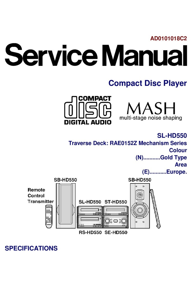
  9. Technics SL-HD505 User manual

Technics SL-HD505 User manual

Mechanism:
Mechanism:Mechanism:
Mechanism:RAE0152Z Mechanism Series
nAudio
AudioAudio
Audio
DA
DADA
DA converter:
converter:converter:
converter: 1 bit 2 DAC MASH
Digital
DigitalDigital
Digital output
outputoutput
output terminal:
terminal:terminal:
terminal: Opticalx1
nPickup
PickupPickup
Pickup
Wavelength
WavelengthWavelength
Wavelength:
:::780nm
nFormat
FormatFormat
Format
Sampling
SamplingSampling
Sampling frequency:
frequency:frequency:
frequency: 44.1kHz
nGeneral
GeneralGeneral
General
Dimensions
DimensionsDimensions
Dimensions (WxHxD):
(WxHxD):(WxHxD):
(WxHxD): 202x76x254mm
Weight:
Weight:Weight:
Weight: 1.4kg
Power
PowerPower
Power Supply[For
Supply[ForSupply[For
Supply[For (E)
(E)(E)
(E) area
areaarea
area only]:
only]:only]:
only]: DC13V/10V
©
©©
©1999 Matsushita Electric Industrial Co., Ltd. All
rights reserved. Unauthorized copying and
distributionis a violation of law.
SL-
SL-SL-
SL-HD505
HD505HD505
HD505
Colour
(S)....................Silver Type
Areas
PP....................U.S.A. and Canada.
E......................Europe.
System:SC-HD505
SC-HD505MD
Bicause of unique interconnecting cables, when a
component requires service, send or bring in the entire
system.
Note: Refer to the service manual for Model No.SE-
HD505/505MD (ORDER NO.AD9904110C5/
AD9904116A2) for information on “ACCESSORIES”,
“INSTALLATION”, “CONNECTION” and “PACKAGING”.
Power
PowerPower
Power Consumptio
ConsumptioConsumptio
Consumption[For
n[Forn[For
n[For (E)
(E)(E)
(E) area
areaarea
area only]:
only]:only]:
only]: 10W
Notes:
Notes:Notes:
Notes:
1.Design and specifications are subject to change without notice.
2.Dimensions and weight are approximate.
nSystem
SystemSystem
System
SC-
SC-SC-
SC-HD505:
HD505:HD505:
HD505:
Tuner:ST-HD505,Compact
CompactCompact
Compact Disc
DiscDisc
Disc Player:SL-H
Player:SL-HPlayer:SL-H
Player:SL-HD505
D505D505
D505,Amplifier:SE-
HD505,Cassette Deck:RS-HD505,Speakers:SB-HD505(Made in
MAES.)
SC-
SC-SC-
SC-HD505MD:
HD505MD:HD505MD:
HD505MD:
Tuner:ST-HD505MD, C
CC
Compact
ompactompact
ompact Disc
DiscDisc
Disc Player:SL-
Player:SL-Player:SL-
Player:SL-HD505
HD505HD505
HD505,
Amplifier:SE-HD505MD, Minidisc Deck:SJ-HD505 ,Speakers:SB-
HD505 (Made in MAES.)
C
CC
Co
oo
om
mm
mp
pp
pa
aa
ac
cc
ct
tt
tD
DD
Di
iiis
ss
sc
cc
cP
PP
Pl
llla
aa
ay
yy
ye
ee
er
rr
r
Specification
SpecificationSpecification
Specification
ORDER NO.AD9904111C5
A6
1
11
1 Blue
BlueBlue
Blue LED
LEDLED
LED
2
22
2
2
22
2 Before
BeforeBefore
Before Repair
RepairRepair
Repair
2
22
2
3
33
3 Precaution
PrecautionPrecaution
Precaution of
ofof
of Laser
LaserLaser
Laser Diode
DiodeDiode
Diode
3
33
3
4
44
4 Operating
OperatingOperating
Operating Instructions
InstructionsInstructions
Instructions
4
44
4
5
55
5 Handling
HandlingHandling
Handling Precautions
PrecautionsPrecautions
Precautions for
forfor
for Traverse
TraverseTraverse
Traverse Deck
DeckDeck
Deck
5
55
5
5.1. Handling of traverse deck (optical pickup) 5
5.2. Grounding for electrostatic breakdown prevention 5
6
66
6 Operation
OperationOperation
Operation Checks
ChecksChecks
Checks and
andand
and Component
ComponentComponent
Component Replacemen
ReplacemenReplacemen
Replacement
ttt Procedures
ProceduresProcedures
Procedures
6
66
6
7
77
7 Error
ErrorError
Error Code
CodeCode
Code Display
DisplayDisplay
Display and
andand
and Servo
ServoServo
Servo Adjustment
AdjustmentAdjustment
Adjustment Function
FunctionFunction
Function
11
1111
11
7.1. Error code display procedure 11
7.2. Servo adjustment procedure 11
7.3. Table 1 12
7.4. Table 2 12
8
88
8 Measureme
MeasuremeMeasureme
Measurements
ntsnts
nts and
andand
and Adjustments
AdjustmentsAdjustments
Adjustments
13
1313
13
8.1. Power Supply to This Unit alone 13
8.2. To Check Signals 13
9
99
9 Troubleshoo
TroubleshooTroubleshoo
Troubleshooting
tingting
ting Guide
GuideGuide
Guide
14
1414
14
10
1010
10 Block
BlockBlock
Block Diagram
DiagramDiagram
Diagram
15
1515
15
This equipment (SL-HD505),which is a component of this
system,is supplied with power from the amplifier (SE-
HD505/505MD) through the tuner (ST-HD505/505MD). When
repairing this equipment or checking operation of the system,
be sure to connect the amplifier and tuner with it.
11
1111
11 Schematic
SchematicSchematic
Schematic Diagram
DiagramDiagram
Diagram Notes
NotesNotes
Notes
18
1818
18
11.1. Scheamtic Diagram Notes 18
11.2. Type Illustrationof IC 痴, Transistorsand Diodes 18
12
1212
12 Schematic
SchematicSchematic
Schematic Diagram
DiagramDiagram
Diagram
19
1919
19
13
1313
13 Printed
PrintedPrinted
Printed Circuit
CircuitCircuit
Circuit Board
BoardBoard
Board Diagram
DiagramDiagram
Diagram
24
2424
24
14
1414
14 Wiring
WiringWiring
Wiring Connection
ConnectionConnection
Connection Diagram
DiagramDiagram
Diagram
26
2626
26
15
1515
15 Terminal
TerminalTerminal
Terminal Function
FunctionFunction
Function of
ofof
of IC
ICIC
ICエs
ss
s
27
2727
27
15.1. IC701 (AN8839NSBE2): SERVO AMP 27
15.2. IC702 (MN662790RSA1): SERVO PROCESSOR/DIGITAL
SIGNAL PROCESSOR/DIGITAL FILTER/D-A
CONVERTER 27
15.3. IC703(AN8739SBE2):FOCUS COIL/TRACKING COIL/
TRAVERSE MOTOR/ SPINDLE MOTOR DRIVE 28
15.4. IC403(LC66358C4K97):SYSTEM CONTROL 28
16
1616
16 Replacemen
ReplacemenReplacemen
Replacement
ttt Parts
PartsParts
Parts List
ListList
List
30
3030
30
17
1717
17 Loading
LoadingLoading
Loading Mechanism
MechanismMechanism
Mechanism Parts
PartsParts
Parts Location
LocationLocation
Location
33
3333
33
18
1818
18 Cabinet
CabinetCabinet
Cabinet parts
partsparts
parts Location
LocationLocation
Location
35
3535
35
This equipment, even in the state of it as a single equipment,
permits power supply and operation check. When operating it
as a single equipment without the amplifier and tuner, refer to
the paragraph of "Measurements and Adjustments.
CONT
CONTCONT
CONTENTS
ENTSENTS
ENTS
Page
PagePage
Page Page
PagePage
Page
1
11
1
Blue
BlueBlue
Blue LED
LEDLED
LED
∙
∙∙∙
The LED mounted to each side of the front panel of this set is very sensitive to static electricity. When handling the LED base
plate, be very careful about it.
∙
∙∙∙
Do not replace a blue LED singly. If replaced singly, it may be subject to electrostatic breakdown or deterioration in quality.
When replacing the LED base plate, be sure to replace L and R sides simultaneously to permit the brightness adjustment.
*For configuration at the time of supply of replacement parts,refer to “Printed Circuit Board Diagram.”
2
22
2
Before
BeforeBefore
Before Repair
RepairRepair
Repair
2
SL-
SL-SL-
SL-HD50
HD50HD50
HD505
55
5
3
33
3
Precaution
PrecautionPrecaution
Precaution of
ofof
of Laser
LaserLaser
Laser Diode
DiodeDiode
Diode
3
SL-
SL-SL-
SL-HD50
HD50HD50
HD505
55
5
4
44
4
Operating
OperatingOperating
Operating Instructions
InstructionsInstructions
Instructions
SL-
SL-SL-
SL-HD50
HD50HD50
HD505
55
5
4
The laser diode in the traverse deck (optical pickup) may break
down due to potential difference caused by static electricity of
1.Do not subject the traverse deck (optical pickup) to static
electricity as it is extremely sensitive to electrical shock.
2.The short land between the No. 5 (GND) and No. 4 (LD)
pins on the flexible board is shorted with a solder build-up
to prevent damage to the laser diode. (As shown in Fig. 1.)
To connect to the PC board, be sure to open by removing
the solder build-up, and finish the work quickly.
3.Take care not to apply excessive stress to the flexible board
(FFC).
4.Do not turn the variable resistor (laser power adjustment). It
has already been adjusted. (As shown in Fig. 1.)
1.Human body grounding
Use the anti-static wrist strap to discharge the static
electricity from your body. (As shown in Fig. 2.)
2.Work table grounding
Put a conductive material (sheet) or steel sheet on the area
where the optical pickup is placed, and ground the sheet.
Caution
CautionCaution
Caution:
::
:
The static electricity of your clothes will not be grounded
through the wrist strap. So, take care not to let your clothes
touch the traverse deck (optical pickup).
clothes or human body.So, be careful of electrostatic
breakdown during repair of the traverse deck (optical pickup).
Fig. 1
Fig. 2
5
55
5
Handling
HandlingHandling
Handling Precautions
PrecautionsPrecautions
Precautions for
forfor
for Traverse
TraverseTraverse
Traverse Deck
DeckDeck
Deck
5.1.
5.1.5.1.
5.1.
Handling
HandlingHandling
Handling of
ofof
of traverse
traversetraverse
traverse deck
deckdeck
deck (optical
(optical(optical
(optical pickup)
pickup)pickup)
pickup)
5.2.
5.2.5.2.
5.2.
Grounding
GroundingGrounding
Grounding for
forfor
for electrostatic
electrostaticelectrostatic
electrostatic breakdown
breakdownbreakdown
breakdown prevention
preventionprevention
prevention
5
SL-
SL-SL-
SL-HD50
HD50HD50
HD505
55
5
6
66
6
Operation
OperationOperation
Operation Checks
ChecksChecks
Checks and
andand
and Component
ComponentComponent
Component Replacement
ReplacementReplacement
Replacement
Procedures
ProceduresProcedures
Procedures
6
SL-
SL-SL-
SL-HD50
HD50HD50
HD505
55
5
7
SL-
SL-SL-
SL-HD50
HD50HD50
HD505
55
5
8
SL-
SL-SL-
SL-HD50
HD50HD50
HD505
55
5
9
SL-
SL-SL-
SL-HD50
HD50HD50
HD505
55
5
10
SL-
SL-SL-
SL-HD50
HD50HD50
HD505
55
5
This unit has an error code display function, so that if the unit
operates incorrectly, the fault is displayed using an error code
on the FL display of the tuner (ST-HD505/505MD). It also has
a servo adjustment function for displaying the status of servo
system functions (focus, tracking, CLV) on the tuner´s FL
display.The system control IC and FL display are part of the
tuner so make sure the system has been connected properly
before using these functions. (This unit can be operated
independently, although the error code display and servo
adjustment functions cannot be used.)Use these two functions
for guidance during fault diagnosis and repair.
Note:
Note:Note:
Note:
Check beforehand for scratching or soiling of the test disc
(SZZP1054C), and soiling or other problems with the optical
pickup lens.
7
77
7
Error
ErrorError
Error Code
CodeCode
Code Display
DisplayDisplay
Display and
andand
and Servo
ServoServo
Servo Adjustment
AdjustmentAdjustment
Adjustment Function
FunctionFunction
Function
7.1.
7.1.7.1.
7.1.
Error
ErrorError
Error code
codecode
code display
displaydisplay
display procedure
procedureprocedure
procedure
7.2.
7.2.7.2.
7.2.
Servo
ServoServo
Servo adjustment
adjustmentadjustment
adjustment procedure
procedureprocedure
procedure
11
SL-
SL-SL-
SL-HD50
HD50HD50
HD505
55
5
7.3.
7.3.7.3.
7.3.
Table
TableTable
Table 1
11
1
7.4.
7.4.7.4.
7.4.
Table
TableTable
Table 2
22
2
12
SL-
SL-SL-
SL-HD50
HD50HD50
HD505
55
5
Caution
CautionCaution
Cautions:
s:s:
s:
∙
∙∙∙
I
II
It
tt
tis
isis
is very
veryvery
very danger
dangerdanger
dangerous
ousous
ous to
toto
to look
looklook
look at
atat
at or
oror
or touch
touchtouch
touch the
thethe
the laser
laserlaser
laser beam.
beam.beam.
beam.
(Laser
(Laser(Laser
(Laser radiatio
radiatioradiatio
radiation
nn
nis
isis
is invisibl
invisiblinvisibl
invisible.)
e.)e.)
e.) W
WW
With
ithith
ith the
thethe
the unit
unitunit
unit turned
turnedturned
turned "ON"
"ON""ON"
"ON"
,
,,
, laser
laserlaser
laser radiatio
radiatioradiatio
radiation
nn
nis
isis
is emitted
emittedemitted
emitted from
fromfrom
from the
thethe
the pickup
pickuppickup
pickup lens.
lens.lens.
lens.
∙
∙∙∙
A
AA
Avoid
voidvoid
void exposu
exposuexposu
exposure
rere
re to
toto
to the
thethe
the laser
laserlaser
laser beam,
beam,beam,
beam, especia
especiaespecia
especially
llylly
lly when
whenwhen
when
perform
performperform
performing
inging
ing adjustm
adjustmadjustm
adjustments.
ents.ents.
ents.
This unit SL-HD505 is designed to operate on power
supplied from the Amplifier SE-HD505/505MD through the
Tuner ST-HD505/505MD.When connecting the unit to other
system components, do not connect to the Amplifier SE-
HD505/505MD directly. Be sure to connect this unit through
the Tuner ST-HD505/505MD.When operating the unit SL-
HD505 alone for testing and servicing, without having
power supplied from the Amplifier SE-HD505/505MD, use
the following method.
8.1.
8.1.8.1.
8.1.
Power
PowerPower
Power Supply
SupplySupply
Supply to
toto
to This
ThisThis
This Unit
UnitUnit
Unit alone
alonealone
alone
Apply 10V DC power to the section between TP402 (far side
from rear panel of R441) and earth plate (E401). (As shown in
Fig. 3.)
8.2.
8.2.8.2.
8.2.
To
ToTo
To Check
CheckCheck
Check Signals
SignalsSignals
Signals
Connect the oscilloscope or the speaker with built-in amplifier
to the section between JK401-pin16[LINE OUT (Rch)] and
earth plate (E401) (GND) as well as the section between
JK401-pin18 [LINE OUT (Lch)] and earth plate (E401) (GND)
and check if the signals are outputting from this unit. (As shown
in Fig. 3.)
8
88
8
Measuremen
MeasuremenMeasuremen
Measurements
tsts
ts and
andand
and Adjustments
AdjustmentsAdjustments
Adjustments
Fig. 3
13
SL-
SL-SL-
SL-HD50
HD50HD50
HD505
55
5
9
99
9
Troubleshoot
TroubleshootTroubleshoot
Troubleshooting
inging
ing Guide
GuideGuide
Guide
14
SL-
SL-SL-
SL-HD50
HD50HD50
HD505
55
5
10
1010
10
Block
BlockBlock
Block Diagram
DiagramDiagram
Diagram
Laser
power
drive
27
4
5
28
OPTICAL PICKUP
Semiconductorl
aser
Photo detector
Q701
6
7
Vref.
Vref.
Subtracter
Ach
VCBA
Bch
1Vref.
Vref. Ech
VCBA
Fch
F
2
Vref.
Vref.
Subtracter
2316
A
B
E
+B2
AN8839NSBE2
IC701
SERVO AMP
Vref.
Vref.
+B2
Vref.
13
Vref.
Vref.
Vref.
26
VREF
14
3+B2
Vref. 24
FE
BDO
11
3
TENV
RF
DET.
+B2
OFTR
DET.
10
+B2
19
15
RFENV
/RFDET
17
OFT
89
VREF
TE
FBAL
TBAL
Focus coil
Tracking coil
F-
F+
T-
T+
M702
SPINDLE
MOTOR
M701
TRAVERSE
MOTOR
VREF
22
17
Focus
coil drive
16
D4+
D4-
11
Traverse
motor
drive
10
D1+
D1-
13
12
D2+
D2-
TRV+
TRV-
M
1
Spindle
motor
drive
IN3
24
IN4
23
15
Tracking
coil drive
14
D3+
D3-
Reset
signal
generator
/RST
PGND1
PGND2
8
19 +B1
7
20
PVcc1
PVcc2
IN1
6
IN2
3
PC2
4
TRD
FOD
TVD
ECS
ECM
PC
ENV
OFTR
/RFDET
FE OUT
V
CC
VREF
GND
TEOUT
PDOWN
FBAL
TBAL
PDF
PDE
PDB
LDON
PDA
LD
LPD RF RFIN CSBRT CEA
EE
F F
B
C
C
A
D
D
SP+
SP-
M
Vref.
(VREF)
TJ702
TEIN
22
(RF)
TJ701
BDO
DET. 12
BDO
FE IN
25
LDON
AN8739SBE2
IC703
FOCUS COIL / TRACKING
COIL / TRAVERSE MOTOR /
SPINDLE MOTOR DRIVE
SL-
SL-SL-
SL-HD50
HD50HD50
HD505
55
5
15
/FLOCK
/TLOCK
1 bit DAC
PWM logics
76
RSEL
44
ARF
46
DRF
47
41
52
PLLF
48
EFM
53
PCK
14
SQCK
80
SSEL
73
8 times oversampling/
digital filter
9
MLD
68
MSEL
75
OUTR
PWM
(R)
OUTL
PWM
(L)
MLD
MN662790RSA1
IC702
SERVO PROCESSOR / DIGITAL SIGNAL PROCESSOR
DIGITAL FILTER / D/A CONVERTER
Rch
PSEL
78
7
Digital deemphasis
Switch-
ing
Q702
+B2
450 60
DV
DD
1
AV
DD
2
V
DD
79 80
SSEL
78
PSEL
IOSEL
CLVS
CRC
BLKCK
/CLDCK
SBCK
SUBC
DEMPH
A/D converter Input port Servo
timing generator
Subcode
buffer
DSL / PLL VCO
EFM demodulation /
Sync interpolation
Subcode demodulation
5745157
DVss1
AVss1
AVss2
Vss
16k
SRAM
Circ error correction/
deinterleave
Digital audio
interface
Digital audio
interface
Interporation/
soft muting/
digital attenuation
Servo CPU
D/A
converter
Output
port
Micro computer
interface
VCO Timing
generator
pitch control
70
66
67
13
62
56
55
BLKCK
SBCK
SUBC
SQCK
SUBQ
15
SUBQ
SPEED
PLLF2
DSLF
MCLK MCLK
MDATA
8
MDATA
STAT
17
STAT
VCOF2
54
VCOF
49
BYTCK
61
SMCK
19
FCLK
63
CSEL
20
MSEL
79
X2
59 59
X1
FE
TE
RFENV
32 33 34
FE
TE
RFENV
TRCRS
VDET
BDO
37 35 39
BDO
/RFDET
OFT
38 36
/RFDET
OFT
10 43 40
SENSE
WVEL
LDONLDON
FBAL FBAL
TBAL TBAL
FOD FOD
TRD TRD
TVD TVD
VREF VREF
TRV
KICK
DSLF2 DSLF2
DMUTE
BCLK
SRDATA
LRCK
PC PC
ECS ECS
ECM ECM
IPFLAG
FLAG
11
12
30
31
28
27
22
29
21
26
42
16
1
3
2
23
25
24
64
65
6
TX
AV
DD
1
72
V
CC
5V
77 71
/TEST
18
/RST
+B2
+B2
DSLF2
45
IREF
+B2
+B2
+B2
X701
(33.8688MHz)
/RST
+B2
CD-text
buffer
SL-
SL-SL-
SL-HD50
HD50HD50
HD505
55
5
16
25
REST
SW
LC66358C4K97
IC403
SYSTEM CONTROL
TC74HCT7007A
IC409
CONVERTER
(3.3V to 5V)
SVRST
BLKCK
SQCK
7
MDATA
MCLK
STAT
27
REQ
26
CS
Q403
Inter-
face
CLK
31
Inter-
face
DTO
29
DTI
28
Q401,
402
SPEED
1,2,
48
STR0~2
KEY0~2
44~46
KEY MATRIX
(S801~808)
OSC2
OSC1
20
17 21
/RST
CLKSPD
X401
(4.19MHz)
Q411
M
LOADING
MOTOR
5
2,4,6,8
+B1
3
7
1
9
TA7291S
IC790
MOTOR DRIVE
OPEN
34
CLOSE
33
39
V
DD
Reset +B4
Q404,415
Regulator
Q405
+B1
+B4
+B(13V)
1
CS
8
JK401
2
3
4
5
6
7
9
12
13
14
15
16
17
18
+B3
CD REQ
CT
+B(10V)
D.GND
CLK
DATA
19
11
10
Switch-
ing
NC
Rch
A.GND
Lch OUT
CLK
SPD
To Tuner/
Cassette Deck
Block Diagram
Rch OUT
A.GND
BLKCK
4
SUBQ
SUBQ
STAT
89
13
5
3
12
6
4
Y3A3
Y5A5
Y2A2
Y1A1
7
GND
+B3
Vcc
/MLD
NC
NC
NC
NC
NC
TP401
TP402
Regulator
LM2940T5M
IC401
Regulator
LM2940T5M
IC400
+B2
T0TX178
IC402
TRANSMISSION
MODULE
MLD
MDATA
MCLK
/RST
SPEED
3
8
+B4
9
DQSY
+B4
12
HOLD
13
14
16
V
SS
15
TEST
3738
+B4
40 41
CDUINT
MODEL
OPEN
SW
36
S790
(OPEN
DET.)
CLOSE
SW
35
S791
(CLOSE
DET.)
10
LEDSTOP
LEDPLAY
LED
drive
11
Q408,
409
D801
()
DISPLED
LED
drive
Q412~
414
32
D901
(LIGHT)
D902
(LIGHT)
+B3
22
47
S701
(REST)
+B2
SQCK
DIGITAL
OPTICAL OUT
14
D411
+B4
Note: Signal line : CD signal
SL-
SL-SL-
SL-HD50
HD50HD50
HD505
55
5
17
This schematic diagram may be modified at any time with the
development of new technology.
Notes:
Notes:Notes:
Notes:
∙
∙∙∙
S701 : Rest position detect switch in “OFF” position.
(It turns “ON” when optical pickup comes to
innermost periphery)
∙
∙∙∙
S790 : CD tray open detection switch.
∙
∙∙∙
S791 : CD tray close detection switch.
∙
∙∙∙
S801 : Stop ( ) switch.
∙
∙∙∙
S802 : Play ( ) switch.
∙
∙∙∙
S803 : Pause ( ) switch.
∙
∙∙∙
S804 : CD tray open/close ( OPEN/CLOSE)
switch.
∙
∙∙∙
S805 : F. skip/ search ( ) switch
∙
∙∙∙
S806 : R. skip/ search ( ) switch.
∙
∙∙∙
S807 : CD text select (CD TEXT) switch.
∙
∙∙∙
S808 : AI edit (AI EDIT) switch.
∙
∙∙∙
Indicated voltage values are the standard values for
the unit measured by the DC electronic circuit tester
(high-impedance) with the chassis taken as
standard. Therefore, there may exist some errors in
the voltage values, depending on the internal
impedance of the DC circuit tester.
No mark: CD STOP
( ): CD play [1kHz, L+R, 0dB]
Importa
ImportaImporta
Important
ntnt
nt safety
safetysafety
safety notice:
notice:notice:
notice:
Components identified by mark have special
characteristics important for safety.
Furthermore, special parts which have purpose of
fire-retardant (resistors), high-quality sound
(capacitors), low-noise (resistors), etc. are used.
When replacing any of components, be sure to use
only manufacture´s specified parts shown in the
parts list.
Caution
CautionCaution
Caution!
!!
!
IC and LSI are sensitive to static electricity.
Secondary trouble can be prevented by taking
care during repair.
Cover the parts boxes made of plastics with
aluminum foil.
Ground the soldering iron.
Put a conductive mat on the work table.
Do not touch the legs of IC or LSI with the fingers
directly.
Voltage
VoltageVoltage
Voltage and
andand
and signal
signalsignal
signal lines
lineslines
lines
: Positive voltage line
: CD signal line
11
1111
11
Schematic
SchematicSchematic
Schematic Diagram
DiagramDiagram
Diagram Notes
NotesNotes
Notes
11.1.
11.1.11.1.
11.1.
Scheamtic
ScheamticScheamtic
Scheamtic Diagram
DiagramDiagram
Diagram Notes
NotesNotes
Notes
11.2.
11.2.11.2.
11.2.
Type
TypeType
Type Illustration
IllustrationIllustration
Illustration of
ofof
of IC’s,
IC’s,IC’s,
IC’s, Transistors
TransistorsTransistors
Transistors and
andand
and Diodes
DiodesDiodes
Diodes
AN8839NSBE2 AN8739SBE2 TC74HCT7007A LC66358C4K97 MN662790RSA1 TA7291S
LM2940T5M
2SD2137PQTA
UPC29M33T
MA8082MTX
MA8039LTX
T0TX178
MA111TX
2SB956RTX
MA728TX MA28TATX
2SB709STX
2SC4081STX
DTA143XUT106
DTC114YUT106
DTC143EUT106
DTC143XUA106
SML79420C
115
14
28
1
26
14
13
6
20
21
7
1
7
8
14
LC.......
1
12
13
24
25
36
37
48
G
IO
IO
G
123
C
BE
E
C
B
C
BE
A
Ca
A
Ca
A
Ca
A
Ca
A
Ca
A
Ca
Ca A
Ca A
A
A
A
Ca
Ca
A
Anode
Cathode
Ca
A
Anode
Cathode
Ca
A
Anode
Cathode
Anode
Cathode
Ca
A
A
Anode
Cathode Anode
9
1
1............
.
.
.
.
.
.
.
.
.
.
.
............
.
.
.
.
.
.
.
.
.
.
.
20
21
40
41
60
61
80
18
SL-
SL-SL-
SL-HD50
HD50HD50
HD505
55
5
12
1212
12
Schematic
SchematicSchematic
Schematic Diagram
DiagramDiagram
Diagram
8 7 6 5
1 2 3 4
NBOUT
GND
NAOUT
VREF
GND
Vcc
BIN
AIN
M
M
14 15 16 17 18 19 20
13 12 11 10 987
21 22 23 24 25 26
654321
NC
RSTIN
IN3
IN4
VREF
Vcc
NC
GND
PVcc2
PGND2
NC
D4+
D4
D3+
D3
/RST
NC
IN2
PC2
NC
IN1
NC
GND
PVcc1
PGND1
NC
D1
D1+
D2
D2+
C
A
B
D
E
F
G
15
14
13
1616
15
14
13
1212
11
8
7
6
5
4
3
2
1
11
10
9
8
7
6
5
4
3
2
1
10
9
1516171819202122232425262728
1413121110987654321
PDE
PDF
Vcc
PDA
PDB
LPD
LD
RF
RFIN
CSBRT
CEA
BDO
LDON
GND
FBAL
TBAL
VREF
FEN
FEOUT
TEOUT
TEN
NC
NC
ENV
NC
OFTR
PDOWN
/RFDET
A
B
C
D
TP36
TP35
C737
0.1
C736
0.1
TP38
TP37
M702
SPINDLE
MOTOR
M701
TRAVERSE
MOTOR
AB CD
C735
0.1
C734
10V220
BADC BA
R736
100
AB
R729
3.9K
R728
3.9K
C739
1500P
C738
0.01
R724
18K
R735
100
R723
6.8K
R731
6.8K
R715
1K
C715
2700P
R725
390
C714
6.3V100
C713
0.1
C712
0.1
C711
0.1
R708
22K
R707
39K
TP42 TP40
C749
2200P
R702
10K
C747
180P
R744
120K C710
120P
R705
150K
TP33 TP32
R704
1K
R706
1K
IHGFEDC
C742
0.027
B
A
R701
4.7
C701
6.3V33
CN701
(RF)
TP30 C716
820P
TJ701
A
B
C
D
E
D
E
C
A
B
DCB A
C751
0.1 C750
0.1
(VREF)
TJ702
C702
0.1
C706
2700P
C707
0.027
C704
0.1
C703
6.3V100
Q701
2SB709STX
LASER POWER
DRIVE
IC701
AN8839NSBE2
SERVOAMP
IC703
AN8739SBE2
FOCUS COIL/
TRACKING COIL/
TRAVERSE MOTOR/
SPINDLE MOTOR DRIVE
TRACKING
COIL
FOCUS
COIL
0.1
2
12
11
3
8
10
5
4
9
680P
680P
1K
0.1
0.047
6
Vcc
PDF
PDE
LD
GND
NB
GND
GND
NA
VREF
LPD
GND
T+
T
F+
F
A
LD
5V
7.7V
C752
1000P
R749
4.7K
R727
3.9K
TP29
OPTICAL PICKUP
CD SERVO CIRCUIT
SCHEMATIC DIAGRAM 1
NOTE:
The number which noted at the connectors
on the schematic diagram as
"SCHEMATIC DIAGRAM 1" or
"SCHEMATIC DIAGRAM 2"
indicates fhe schematic diagram
serial number located on the left corner
in the schematic diagram.
1.7V 3.4V1.7V 1.7V 1.7V (0.2V)
0V (2.5V)
3V (1.5V)
1V 0.7V 2.1V
(2.3V) 1.8V 0V (3.3V)
0V
1.7V 1.7V 1.7V 1.7V 1.7V 1.7V 1.7V 1.7V 0V 3.3V
(0V)
(0.4V) (0.2V) (0.1V) (0.4V)
0V (0.2V)
0V 0V 0V 0V 7.8V 7.8V 1.7V 1.7V 1.7V
1.7V1.7V3.3V1.7V1.7V (0V)
0V 0V 0V 0V
(0.1V) (0.7V) (0.6V) 7.8V
PLAY 0.2V
PP
2ms. 0.1V/DIV.
PLAY
2ms. 0.1V/DIV.
0.6V
PP
PLAY
0.8V
PP
3.4V
7.8V
0.3V
(1.8V)
3.4V (2.5V)
3V
:POSITIVE VOLTAGE LINE :CD SIGNAL LINE
0.5 s. 0.2V/DIV.
SL-
SL-SL-
SL-HD50
HD50HD50
HD505
55
5
19
10K
4.7K
61
60
59
58
57
56
55
54
53
52
51
50
49
48
47
46
45
44
43
42
41
62 63 64 65 66 67 68 69 70 71 72 73 74 75 76 77 78 79 80
1
2
3
4
5
6
7
8
9
10
11
12
13
14
15
16
17
18
19
20
2122232425262728293031323334353637383940
BCLK
LRCK
SRDATA
DV
DD
1
DVss1
TX
MCLK
MDATA
MLD
SENSE
/FLOCK
/TLOCK
BLKCK
SQCK
SUBQ
DMUTE
STAT
/RST
SMCK
CSEL
TRV
TVD
PC
ECM
ECS
KICK
TRD
FOD
VREF
FBAL
TBAL
FE
TE
RFENV
VDET
OFT
TRCRS
/RFDET
BDO
LDON
PLLF2
DSLF2
WVEL
ARF
IREF
DRF
DSLF
PLLF
VCOF
AV
DD
2
AVss2
EFM
PCK
VCOF2
SUBC
SBCK
Vss
X1 IN
X2 OUT
V
DD
BYTCK
/CLDCK
FCLK
IPFLAG
FLAG
CLVS
CRC
DEMPH
RESY
IOSEL
/TEST
AV
DD
1
OUTL
AVss1
OUTR
RSEL
IOV
DD
PSEL
MSEL
SSEL
2321 2220191817161514
132 4 5 6 7 8 9 10 11 12 13
TP15 TP19 TP22
A
B
TP23
TP21
C727
50V1
C728
50V1
C725
1000P
C726
1000P
R718
1K
R717
1K
C754
470P
C730
0.1
C731
6.3V220
R721
100
C732
6.3V220
C733
0.1
C753
470P
A
B
CN702
C743
0.1
TP17
L701
AB
TP14TP13
C
TP12TP8TP7TP6
TP4
TP3
DEFGHI
TP1
S701
(REST)
TP16
C745
0.1
A
B
C
D
E
F
G
H
I
GEDCBAABC EFGHI
Q702
DTC143XUA106
SWITCHING
R712
220
C718
0.1
C717
0.1
C744
8200P
R709
68K
R711
82K
C722
3P
X701
(33.8688MHz)
R714
6.8K
C721
3P
C724
0.1
C723
10V220
IC702
MN662790RSA1
SERVO PROCESSOR/
DIGITAL SIGNAL PROCESSOR/
DIGITAL FILTER/
D/A CONVERTER
+B(2)
Rch OUT
5V
5V
5V
SUBC
/RST
STAT
SBCK
SUBQ
SQCK
BLKCK
SPEED
MLD
MDATA
MCLK
P.GND
+B(1)
TX
CLDCK
D.GND
A.GND
Lch OUT
RESTSW
L702
D
R753
10
F
R741
47K R742
220K
C760
0.1
NC
NC
TP20
To MAIN CIRCUIT(CN402)
on SCHEMATIC DIAGRAM 3
SCHEMATIC DIAGRAM 2
C
TP11
TP10
TP9
TP2 TP5
7.8V
3.4V
3.4V
3.4V
3.4V
1.7V
0V
3.4V
0V
2.9V
0V(1.7V)
0V(3.3V)
3.4V
1.7V
3.4V(0V) 1.7V
1.7V
1.7V
1.7V
1.7V
1.7V
1.7V
1.7V
1.7V
1.7V
3.3V(0V)
0V(3.3V)0V
0V
1.7V
1V
(1.2V)
1.7V
0V
3.4V
1.6V
1.6V
3.4V
3.4V
3.1V
1.6V
3.4V
1.6V
3.1V
3.4V
PLAY
1kHz, 0dB
2.2V
PP
PLAY
0V
3.3V
T 13.3ms.
300mV
PP
F=33.8688MHz
2.4V
PP
F=33.8688MHz
PLAY
0.8V
PP
PLAY
0V
3.3V
F=75Hz
PLAY
2ms. 0.1V/DIV.
0.6V
PP
PLAY 0.2V
PP
2ms. 0.1V/DIV.
PLAY
0V
2.9V
T 13.3ms.
3.4V
0V
PLAY
0V
3.3V
T 26.6ms.
3.4V
3.4V
3.4V
1.7V
1.7V
:POSITIVE VOLTAGE LINE :CD SIGNAL LINE
0.5 s. 0.2V/DIV.
PLAY
0V
3.3V
0.1 s. 2V/DIV.
SL-
SL-SL-
SL-HD50
HD50HD50
HD505
55
5
20

Other Technics CD Player manuals

Technics SL-PD967 User manual

Technics

Technics SL-PD967 User manual

Technics SL-XP700 User manual

Technics

Technics SL-XP700 User manual

Technics SL-PG440A User manual

Technics

Technics SL-PG440A User manual

Technics SL-MC70 User manual

Technics

Technics SL-MC70 User manual

Technics SLPG4 - COMPACT DISC PLAYER User manual

Technics

Technics SLPG4 - COMPACT DISC PLAYER User manual

Technics SL-P3 User manual

Technics

Technics SL-P3 User manual

Technics SL-PS7 User manual

Technics

Technics SL-PS7 User manual

Technics BL-PD349 User manual

Technics

Technics BL-PD349 User manual

Technics SL-P1 User manual

Technics

Technics SL-P1 User manual

Technics SL-P1000 User manual

Technics

Technics SL-P1000 User manual

Technics SL-XP140 User manual

Technics

Technics SL-XP140 User manual

Technics SL-G700 User manual

Technics

Technics SL-G700 User manual

Technics SLMC60 - COMPACT DISC CHANGER User manual

Technics

Technics SLMC60 - COMPACT DISC CHANGER User manual

Technics sl-pd887 User manual

Technics

Technics sl-pd887 User manual

Technics SL-P999 User manual

Technics

Technics SL-P999 User manual

Technics SL-PJ37A User manual

Technics

Technics SL-PJ37A User manual

Technics SL-PG480A - schematics User manual

Technics

Technics SL-PG480A - schematics User manual

Technics SL-G700M2 Installation and service instructions

Technics

Technics SL-G700M2 Installation and service instructions

Technics SL-XP600 User manual

Technics

Technics SL-XP600 User manual

Technics CQ-DP5EU/EC User manual

Technics

Technics CQ-DP5EU/EC User manual

Technics SL-EH50 User manual

Technics

Technics SL-EH50 User manual

Technics SL-G700 User manual

Technics

Technics SL-G700 User manual

Technics SL-PG340A User manual

Technics

Technics SL-PG340A User manual

Technics SL-PD867 User manual

Technics

Technics SL-PD867 User manual

Popular CD Player manuals by other brands

Gemini CFX-30 Operation manual

Gemini

Gemini CFX-30 Operation manual

Sony CFD-440 operating instructions

Sony

Sony CFD-440 operating instructions

Arcam Alpha 9 Handbook

Arcam

Arcam Alpha 9 Handbook

Philips AZ1316 Specifications

Philips

Philips AZ1316 Specifications

Clatronic CDP 511 Instruction manual & guarantee

Clatronic

Clatronic CDP 511 Instruction manual & guarantee

Sony XDCAM PDW-V1 Operation manual

Sony

Sony XDCAM PDW-V1 Operation manual

Philips AZ1027 user manual

Philips

Philips AZ1027 user manual

Ayre CX-7 owner's manual

Ayre

Ayre CX-7 owner's manual

Sony CDP-CA80 Service manual

Sony

Sony CDP-CA80 Service manual

Kenwood KDC-C510FM instruction manual

Kenwood

Kenwood KDC-C510FM instruction manual

Sony CDP-C250Z Service manual

Sony

Sony CDP-C250Z Service manual

Cary Audio Design CD 308 operating manual

Cary Audio Design

Cary Audio Design CD 308 operating manual

Onkyo DV-CP706 Setup guide

Onkyo

Onkyo DV-CP706 Setup guide

Cambridge Audio TOPAZ CD10 - V3 user manual

Cambridge Audio

Cambridge Audio TOPAZ CD10 - V3 user manual

Memorex MPD-8505CP operating instructions

Memorex

Memorex MPD-8505CP operating instructions

Kenwood DPC-141 instruction manual

Kenwood

Kenwood DPC-141 instruction manual

SOUNDMASTER DAB970 manual

SOUNDMASTER

SOUNDMASTER DAB970 manual

NAD C 516BEE owner's manual

NAD

NAD C 516BEE owner's manual

manuals.online logo
manuals.online logoBrands
  • About & Mission
  • Contact us
  • Privacy Policy
  • Terms and Conditions

Copyright 2025 Manuals.Online. All Rights Reserved.