manuals.online logo
Brands
  1. Home
  2. •
  3. Brands
  4. •
  5. Technics
  6. •
  7. CD Player
  8. •
  9. Technics SL-PC25 User manual

Technics SL-PC25 User manual

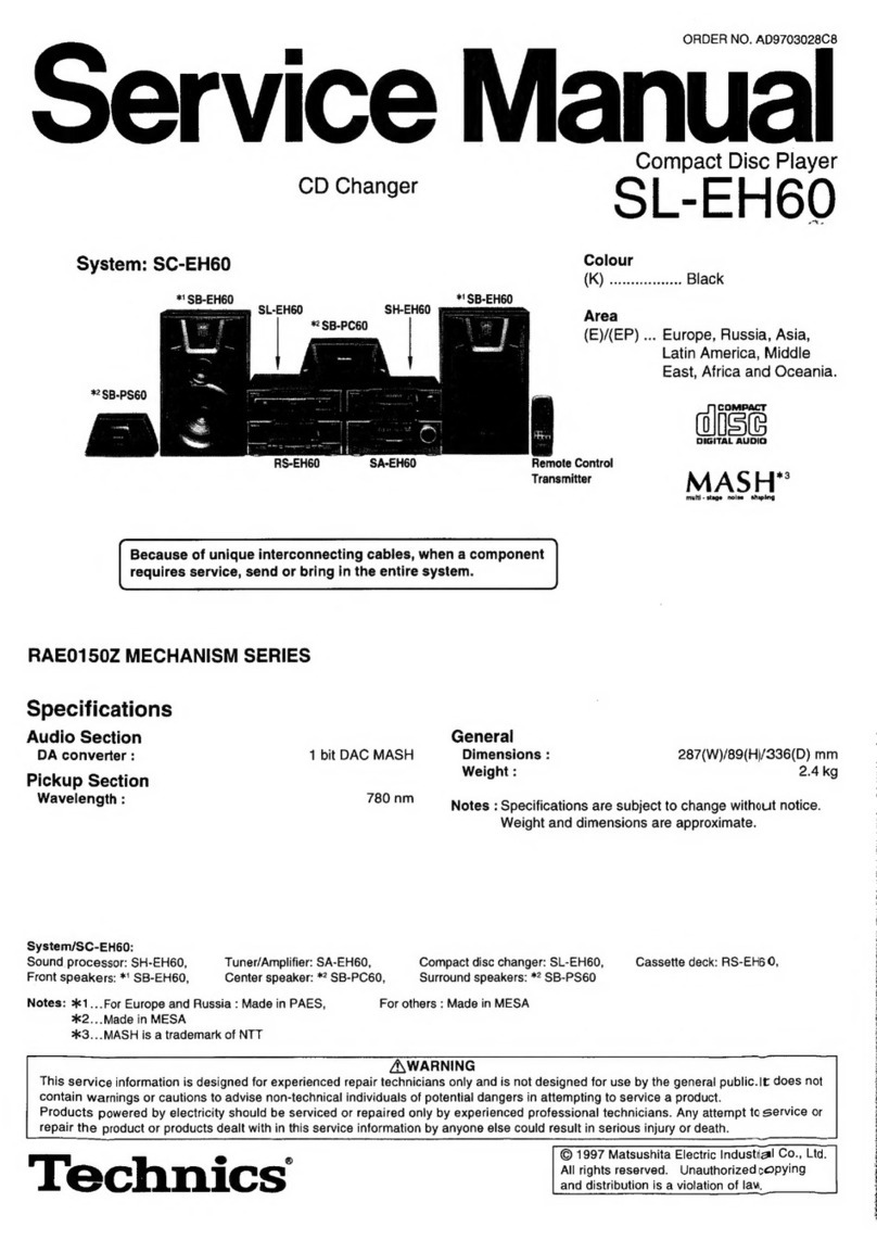
ORDER
NO.
AD9006180C9
Service
Manual
Multi
Compact
Disc
Player
SL-PC25
Color
(K)...
Black
Type
COMPACT
IDIGITAL_|
DIGITAL
AUDIO
Area
Country
Code
Continental
Europe.
(EB)
Great
Britain.
Asia,
Latin
America,
Middie
Near
East
and
Africa.
Far
East-PX.
SL-PC10
MECHANISM
SERIES
(RXK0087)
SPECIFICATIONS
@
Audio
@
Pickup
No.
of
channels
2
(left
and
right,
stereo)
Wavelength
780
nm
Frequency
response
2-20,000
Hz+1
dB
Output
voltage
2
V
(at
0
dB)
@
General
Dynamic
range
96
dB
Power
supply
S/N
ratio
96
dB
For
Continental
Europe:
AC
50/60
Hz,
220
V
For
Great
Britain
and
Oceania:
AC
50/60
Hz,
240
V
For
others:
AC
50/60
Hz,
110
V/127
V/220
V/240
V
MASH‘
(4
DAC)
Power
consumption
138W
1kQ
Dimensions
(WxHxD)
430
x
109.5
x
362
mm
Weight
4.1
kg
0.005%
(1
kHz,
0
dB)
Below
measurable
limit
Total
harmonic
distortion
Wow
and
flutter
DA
converter
Output
impedance
Load
impedance
More
than
10
kQ
Specifications
are
subject
to
change
without
notice.
Weight
and
dimensions
shown
are
approximate
“MASH
®MASH
(Multi-Stage
Noise
Shaping)
is
an
effective
over-
sampling
D/A
conversion
technique
which
realizes
a
high
S/N
ratio
and
needs
no
highly
complex
manufacturing
processes
such
as
a
laser
trimming.
®@MASH
is
trademark
of
NTT
(Nippon
Telegraph
and
Tele-
phone
Corporation).
Panasonic
Tokyo
Sales
Department
Technics
Matsushita
Electric
Industrial
Co.,
Ltd.
Central
P.O.
Box
288,
Osaka
530-91,
Japan
Matsushita
Electric
industrial
Co.,
Ltd.
World
Trade
Center
Bldg.,
4-1,
Hamamatsu-cho,
2-chome,
Minato-ku,
Tokyo
105,
Japan
SL-PC25
M@
CONTENTS
Page
INSTALLATION
...........0..
00
cc
ee
eee
eeeee
2
ACCESSORIES
's
5:8
cee
2S
oie
e6
OS
eo
a
a
ee
ae
2
PRECAUTION
OF
LASER
DIODE
.................
3
CONNECTIONS
..........0..
0000
eee
eee
eae
4
FRONT
PANEL
CONTROLS
AND
FUNCTIONS
.........
5
PLAYING
A
DISC
.........2..22
2002
eee
eee
6,7
REMOTE
CONTROL
TRANSMITTER
..............--
7
HANDLING
PRECAUTIONS
FOR
OPTICAL
PICKUP
......
8
INSTRUCTIONS
FOR
TRAVERSE
OIL
(Part
No,
SZZOL31)
2...
2.
ee
ee
8
DISASSEMBLY
INSTRUCTIONS
..............
9~13
MEASUREMENTS
AND
ADJUSTMENTS
.........
13
~19
TERMINAL
FUNCTION
OF
IC’S
..............
20
~
24
BLOCK
DIAGRAM
.............0002002
a
25
~
27
Mi
INSTALLATION
Transport
lock
The
optical
pickup
is
secured
to
prevent
damage
during
transport.
Be
sure
to
release
it
before
use.
1
2
@
Remove
the
*\clamper.
Lock
shaft
Pull
to
unlock.
@
(in
the
locked
Pull
condition)
NOTE:
IF
THE
UNIT
IS
TRANSPORTED
AGAIN,
PERFORM
THE
FOLLOWING
STEPS:
1.
Turn
the
power
on
and
remove
all
discs
from
the
trays.
2.
PRESS
THE
DISC
SKIP
BUTTON
on
the
top
panel
and
turn
the
power
off.
3.
Insert
the
clamper
into
the
slot
on
the
bottom
of
the
unit
and
turn
it
clockwise.
.
Place
the
unit
with
the
right
panel
facing
downward.
Press
the
lock
shaft
to
the
LOCK
position
(MM
_.
m).
CAUTION:
Do
not
transport
the
unit
without
locking
the
lock
shaft.
SEVERE
DAMAGE
WILL
RESULT.
Soft
cloth
or
similar
material
(to
prevent
scratches)
>
li
ACCESSORIES
Page
INTERNAL
CONNECTION
OF
FL
................
28
SCHEMATIC
DIAGRAM
..............-....
29
~
35
TERMINAL
GUIDE
OF
IC’S
TRANSISTORS
AND
DIODES
................
36
PRINTED
CIRCUIT
BOARDS
................
37
~
40
WIRING
CONNECTION
DIAGRAM
...............-
41
REPLACEMENT
PARTSLIST.................
42~45
EXPLODED
VIEWS
............
0000
eee
eee
46
~
48
RESISTORS
&
CAPACITORS
.................
49,50
PACICUNG
1
orn
Buia
Suse
dace
gay
od
aed:
Beis
ee
ehae
Nada
eos
50
TROUBLESHOOTING
FLOWCHART...........
51~
54
*
TECHNICAL
INFORMATION
*
This
technical
information
is
located
on
pp
45
~56
of
the
SL-PC10
Service
Manual
(Order
No.
AD8904091C1).
Therefore,
refer
to
that
Service
Manual.
Placement
notes
@
This
unit
is
a
precision
instrument.
Be
sure
to
place
it
on
a
flat
surface.
@
Avoid
places
such
as
the
following:
e@Near
any
equipment
or
device
that
generates
strong
magnetism.
®On
any
heat-generating
equipment
or
device,
or
in
any
place
where
the
temperature
is
high
(35°C
or
higher).
eExtremely
cold
places
(5°C
or
below).
eNear
a
tuner
or
TV
(It
may
cause
noise
in
the
broadcast,
or
disturbance
of
the
TV
picture.)
eFor
long
periods
of
time
in
direct
sunlight.
@ln
dusty
or
smoky
locations.
eln
locations
prone
to
vibrations.
®\n
locations
where
the
rear
panel
is
less
than
10
cm
(about
4”)
away
from
the
wall
or
back
of
an
audio
rack.
eWithin
reach
of
children.
@
When
carrying
or
storing
the
unit,
handle
it
with
care
so
it
is
not
subjected
to
any
strong
bumps.
Always
remove
the
disc
before
storing
the
unit
for
any
period
of
time.
@
To
avoid
problems
due
to
vibration.
@Do
not
place
a
book
or
similar
object
under
this
unit.
Do
not
route
the
connection
cables
(of
this
or
other
units)
across
the
operation
panel,
across
the
top,
or
under
the
unit.
@
AC
power
supply
cord....1
@
Stereo
connection
cable....1
@
Dust
cover............
1
SJA187_—(E)
(SJP2249-3)
(RYFO082)
SJA193
(EB)
SJA173
(GN)
RJA0004
(GC,
PX)
®
Remote
control
@
Batteries...........-.0..
2
@
AC
plug
adaptor
......
1
transmitter
.........-.--
1
(EUR64789B)
(UM—4NE/2S)
[SJP9215
(GC,
PX)]
pea
aes
MIPRECAUTION
OF
LASER
DIODE
CAUTION:
This
product
utilizes
a
laser
diode
with
the
unit
turned
“on”,
invisible
laser
radiation
is
emitted
from
the
pick
up
lens.
Wave
length:
780nM
Maximum
output
radiation
power
from
pick
up:
100HW/VDE
Laser
radiation
from
the
pick
up
lens
is
safety
level,
but
be
sure
the
followings:
1.
Do
not
disassemble
the
optical
pick
up
unit,
since
radiation
from
exposed
‘aser
diode
is
dangerous.
2.
Do
not
adjust
the
variable
resistor
on
the
pickup
unit.
It
was
already
adjusted.
3.
Do
not
look
at
the
focus
lens
using
optical
instruments.
4,
Recommend
not
to
look
at
pick
up
Jens
for
a
long
time.
ACHTUNG:
Dieses
produkt
enthalt
eine
laserdiode.
Im
eingeschalteten
zustand
wird
unsichtbare
laserstrahlung
von
der
lasereinheit
abgestrahlit.
Wellenlange:
780nM
Maximale
strahlungsleistung
der
lasereinheit:
100
ujW/VDE
Die
strahtung
an
der
lasereinheit
ist
ungefahrlich,
wenn
folgende
punkte
beachtet
werden:
1.
Die
lasereinheit
nicht
zerlegen,
da
die
strahlung
an
der
freigelegten
laserdiode
gefahriich
ist.
2.
Den
werksseitig
justierten
einstellregler
der
lasereinreit
nicht
verstellen.
3.
Nicht
mit
optischen
instrumenten
in
die
fokussierlinse
blicken.
4.
Nicht
Gber
langere
zeit
in
die
fokussierlinse
blicken.
ADVARSEL:
|
dette
a
apparat
anvendes
laser.
SYNCHRO
TOT
LINE
OUT”
EpiT
Rear
panel
of
this
unit
e
Use
of
caution
labels
CLASS
1
LASER
PRODUCT
Note:
©
Mark
is
used,
x
Mark
is
not
used.
RQLS0021
Others
Obs:
Apparaten
innehaller
laser
Komponent
av
hdger
laserklass
an
klass
1.
RQLS0021
ADVARSEL:
USYNLIG
LASERSTRALING
VEO
ABNING,
NAR
SIKKERHEDSAF-
BRYDERE
ER
UDE
AF
FUNKTION.
UNDGA
UDSATTELSE
FOR
STRALING.
VORSICHT-Unsichtbare
|
OANGER-Invisible
Laserstrahlung,
wenn
§f
laser
radiation
when
Abdeckung
gedffnet.
open.
Nicht
dem
Strahl
AVOID
DIRECT
EX-
aussetzen.
eacsoozi
ff
POSURE
TO
BEAM.
1B
OY40)
li
CONNECTIONS
Before
making
connections,
be
sure
that
the
power
to
this
unit
and
all
other
connected
equipment
is
first
turned
off.
SYNCHRO
LINE
OUT
Epit
Rear
panel
of
this
unit
(R)
(L)
Fes
5
[2]
3]
To
the
household
|
e
AC
outlet
To
the
“CD”
or
‘“AUX”
To
the
‘SYNCHRO
EDIT”
terminals
of
the
amplifier
terminal
of
the
Technics
cassette
deck
[1]
Stereo
connection
cable
(included)
;
How
to
install
the
dust
cover.
[2]
L-type
cable
Note:
This
cable
is
included
only
with
the
cassette
deck
having
the
appropriate
“SYNCHRO
EDIT”
terminal.
[3]
AC
power
supply
cord
(included)
Note:
The
configuration
of
the
AC
outlet
and
AC
power
supply
cord
differs
according
to
area.
Mi
FRONT
PANEL
CONTROLS
AND
FUNCTIONS
Control
section
The
functions
indicated
by
the
numbers
with
black
background
(@)
can
also
be
activated
from
the
remote
contro!
transmitter.
(See
page
7.)
Carousel
@)
Power
switch
(power)
Press
(BW
m)
to
switch
the
power
on.
Press
again
(m_.M)
to
switch
the
power
off
@
Remote
control
signal
sensor
(remote
sensor)
o
~@
Random
button
(random)
Press
this
button
to
let
the
microcomputer
make
a
random
selection
of
the
sequence
in
which
discs
and
tracks
are
played
during
continuous
play
or
program
play
Press
the
button
again
to
cancel
the
random
play
mode
©
Repeat
button
(repeat)
Press
this
button
to
activate
the
repeat
mode.
The
repeat
indicator
illuminates.
Press
again
to
cancel
the
repeat
mode.
The
repeat
indicator
will
no
longer
illuminate
©
Time
mode
button
(time
mode)
Use
this
button
to
select
the
desired
time
mode.
The
display
information
will
change
as
follows
each
time
the
button
is
pressed
(1)
Track
number
and
its
elapsed
play
time
@
Track
number
and
remaining
time
of
current
track
@
Total
track
numbers
and
playing
time
of
the
current
disc
@
Total
elapsed
play
time
of
the
current
disc
©
Buttons
for
edit
function
(
IMIZETI
)
eEdit
tape
length
button
(tape
length)
When
compact
discs
are
to
be
recorded
to
tape,
this
button
can
be
used
to
calculate
the
number
of
tracks
that
can
be
recorded
on
each
side
of
the
tape,
depending
on
the
length
of
the
cassette
tape
used.
so
that
as
little
tape
as
possible
is
wasted.
eAuto
link
button
(auto
link)
This
button
can
be
used
for
automatic
edit
recording
from
several
discs.
°
Search
buttons
(4<
search
>P)
Use
these
buttons
to
move
the
pickup
forward
and
backward
©
Disc
button
(disc
1~5)
These
buttons
are
used
to
select
the
desired
disc
for
sequential
or
program
piay
Disc
trays
(1~5)
One
disc
per
tray
can
be
loaded
Stop
button
(MM
stop)
Pause
button
(il
pause)
Play
button
(P
play)
©20ee6
©
Disc
skip
button
(disc
skip)
Each
time
this
button
is
pressed,
the
carousel!
will
rotate
ina
clockwise
direction
to
the
next
tray
position.
This
allows
for
loading
or
unloading
of
discs
This
button
is
also
used
to
select
the
next
disc,
in
the
continuous
or
random
play
mode
@®
Program/continue
button
(program/continue)
This
button
is
used
to
select
either
the
continuous
play
or
program
play
mode.
The
mode
changes
each
time
the
button
is
pressed
The
continuous
play
mode
is
automatically
selected
when
the
power
is
switched
on
Display
section
®
Skip
buttons
(<4
skip
PP!)
Press
one
of
these
buttons
briefly
to
move
the
pickup
(backward
and
forward)
to
the
beginning
of
a
specific
track
Pickup:
The
pickup
is
a
laser
device
that
reads
the
information
on
the
disc
surface.
The
pickup
moves
across
the
disc
as
the
disc
is
played,
but
it
is
not
visible
from
outside
the
cabinet
j
J
Disc
indicators
(<<.
~
«»)
The
indicator
corresponding
to
the
disc
being
played
flashes
during
play
When
the
unit
is
in
the
program
mode,
these
indicators
show
the
programmed
discs.
@
Disc
number/tape
side
display
(disc)
Shows
the
number
(1~5)
of
the
current
disc,
or
shows
the
tape
side
(A
or
B)
in
the
edit
mode.
Track
number
display
(track)
Shows
the
number
(up
to
99)
of
the
current
track
Time/programmed
number
display
(No.,
min,
sec)
This
display
shows
the
elapsed
playing
time
of
the
track
being
played.
When
the
unit
is
in
the
program
play
mode,
this
display
shows
the
program
sequence.
@
Program
play
indicator
({program))
Hluminates
when
the
unit
is
in
the
programming
or
program
play
mode.
@)
Compact
disc
edit
indicator
(
® ©
@)
Random
indicator
({random!
Mluminates
when
the
random
play
mode
is
selected
@
Repeat
indicator
([@5))
lluminates
when
the
repeat
mode
is
activated
llluminates
when
the
edit
mode
is
activat
@
Auto
link
indicator
((link])
Iluminates
when
the
unit
is in
the
condition
that
the
automatic
disc
link
is
possible.
Pause
indicator
(If)
luminates
when
the
pause
mode
is
activated.
Play
indicator
(>)
Iltuminates
when
the
play
mode
is
activated
n
i
0
2)
N
a
li
PLAYING
A
DISC
|
Continuous
play
{from
the
stop
mode)
Continuous
play
refers
to
play
of
the
first
track
of
the
first
disc
to
the
last
track
of
the
last
disc.
2
Open
the
dust
cover.
3
Load
disc(s)
on
the
disc
tray(s).
1
Press
the
power
switch
to
turn
on
(M_.
=).
The
disc
trays
turn
clockwise,
and
the
disc
1
tray
resets
to
the
front
position
Continuous
play
is
automatically
selected
when
the
power
is
switched
on.
If
the
program
play
indicator
is
illuminated,
press
the
program/continue
button
Disc
indicators
al
LILI
track
|
<>
<ap
aap
<a
ae!
7)
7)
i
ms
a
i
|
|
H
i
Nh
Open
the
dust
cover.
wo
Load
the
disc(s)
on
the
disc
tray(s).
®Continuous
play
begins
from
disc
1
when
the
play
button
is
pressed.
¢For
loading
disc
5,
press
the
disc
skip
button
or
turn
the
disc
trays
manually.
Notes:
*Do
not
touch
the
disc
tray
while
rotating.
*During
play,
other discs
can
be
changed.
¢Discs
of
the
8
cm
(3”)
size
and
12
cm
(5")
size
cannot
be
used
together
on
the
same
number
disc
tray.
The
disc
skip
button
cannot
be
used
during
program
play.
if
intermittent
noises
are
produced
while
the
carousel
is
rotating,
this
means
that
the
lock
shaft
is
not
released.
Set
the
power
switch
to
off
and
release
the
shaft
according
to
the
procedure
on
page
2.
program/
continue
pause
4
Press
the
play
button
to
start
play.
The
play
indicator
will
illuminate
and
continuous
play
will
start.
The
indicator
corresponding
to
the
disc
being
played
flashes.
SE
BN
ARE
ee
!
mer
7s
t
tee
tnt
wack
min
tor
Play
indicator
At
the
end
of
the
last
track
of
the
last
disc,
the
unit
switches
to
the
stop
mode
To
briefly
interrupt
play
Press
the
pause
button.
The
unit
switches
to
the
pause
mode
and
the
pause
indicator
illuminates.
Press
the
play
button
to
resume
play.
Pause
mode:
Play
is
stopped,
but
the
pickup
remains
where
it
was
at
the
time
when
the
pause
button
was
pressed.
The
disc
rotates
while
the
unit
is
in
the
pause mode.
To
stop
play
Press
the
stop
button.
Stop
mode:
in
the
stop
mode
the
pickup
is
at
its
rest
position;
the
disc
does
not
rotate,
and
the
display
will
show
all
zeros.
Continuous
play
continues
G29d°
1S
To
select
the
desired
track
(or
disc)
to
be
played
(trom
the
stop
mode
or
during
play)
By
selecting
the
disc
or
track
to
be
played
first
in
the
play
sequence,
al!
subsequent
tracks
will
be
played
on
that
disc(s)
in
order
from
that
track
to
last.
(There
is
no
need
to
press
the
play
button.)
1
Press
the
disc
select
button.
If
the
disc
only
is
selected,
play
of
ati
tracks
on
that
disc
(beginning
from
its
first
track)
will
begin
in
about
ten
seconds.
For
example:
To
select
the 3rd
disc,
press
the
[3
]
button
The
selected
disc
indicator
will
flash
2
Press
the
skip
([=1])
button
to
select
the
track
number.
Play
will
start
from
the
selected
track
For
example:
To
select
the 9th
track,
press
the
(-=1}
button
8
times
(or
keep
pressing
the
button
until
the
display
shows
“
9").
Track
number
If
you
go
past
the
desired
track,
press
the
[=]
button
to
return
to
the
desired
track.
disc
a
2
Numeric
buttons
e
3
Numeric
buttons
@
By
the
remote
control
transmitter
(See
page
7.)
1
Press
the
disc
button.
2
Press
the
numeric
button
((1)}-(5])
to
specify
the
disc.
3
Press
the
numeric
button
to
specify
the
track.
Play
will
start
from
the
selected
track
To
select
the
10th
and
subsequent
tracks
Press
the
[+10
button
to
select
the
“tens”
digit,
and
then
press
(one
of)
the
[6}-{9]
buttons
to
select
the
“units”
digit
Example:
to
select
the
32nd
track
Press
the(~10|button
three
times
to
select
3,
and
then
press
the
[2]
button.
eSteps
1
and
2
are
not
necessary
if
the
track
is
specified
on
the
1st
disc.
Notes:
elf
a
disc
number
not
on
the
disc
tray
is
specified,
the
next
higher
number
disc
will
be
played.
When
a
track
number
not
on
the
disc
is
specified,
the
selection
cannot
be
entered.
Prog
ram
play
(from
the
stop
mode}
As
many
as
32
selections
from
the
five
discs
can
be
selected
and
programmed
to
play
in
any
desired
sequence.
program/
1
continue
Program/
continue
5
Repeat
steps
2,3
and
4as
desired.
3
Select
the
track
number.
1
Press
the
program/continue
button.
NI
The
piay
mode
will
then
change
from
continuous
play
to
Program
play
For
example:
To
select
the
9th
track,
press
the
(1)
button
|
9
times.
Specified
track
number
eeocenm
im
|
xe
=
a
=
tt
te
ee
ive
LT
sen
no
Dina
+
a
Program
play
indicator
Note:
4
The
mode
does
not
change
if
the
program/continue
button
is
pressed
during
play.
Press
the
program/continue
button.
Programmed
order
2
Press
the
disc
select
button.
For
example:
To
select
the
3rd
disc,
press
the
GG]
button.
=
=
pier
aise
number
5
Repeat
steps
2,
3
and
4
until
the
desired
program
is
completed.
=_
ac
fi
Steps
3
and
4
are
not
necessary
if
selecting
the
disc
only.
¢
rt
t
Step
2
is
not
necessary
to
select
the
disc
number
if
the
next
Sh
aachale:
track
selected
is
on
the
same
disc.
ie
a
ie
Note:
If
selections
of
non-existing
disc(s)
or
track(s)
are
pro-
grammed,
the
corresponding
indicator
(disc
or
track)
will
illuminate
and
the
selection
will
be
included
in
the
program
count.
However,
during
play
the
selection(s)
will
be
cancelled
and
the
subsequent
program
selection
will
be
played.
Note:
If
the
disc
only
is
selected,
all
tracks
on
that
disc
(beginning
from
its
first
track)
wilt
be
programmed.
6
Press
the
play
button
to
start
play.
M@
REMOTE
CONTROL
TRANSMITTER
|
Insertion
of
remote
control
transmitter
batteries
BATTERY
LIFE:
About
1
year.
Use
two
UM-4,
AAA’
(RO3)
size
(1.5
V)
batteries.
@
Notes
concerning
use
of
dry
bat-
teries
®Do
not
use
re-chargeabie
batteries
(Ni-Cd
type)
Be
sure
the
batteries
are
inserted
so that
the
positive
(+)
and
negative
(--}
polarities
are
correct.
Batteries
installed
with
incorrect
polar-
ities
may
leak
and
damage
the
remote
control
transmitter.
Never
subject
the
batteries
to
excessive
heat
or
flame;
do
not
attempt
to
disassemble
them:
and
be
sure
they
are
not
short-circuited
elf
the
remote
control
transmitter
is
not
to
be
used
for
a
long
time,
remove
the
batteries
and
store
them
in
a
cool
dark
place.
¢Always
remove
old,
weak
or
worn-out
batteries
promptly
and
dispose
of
them.
Never
mix
old
and
new
batteries,
nor
batteries
of
different
types
(carbon
or
alkaline)
*Aithough
battery
life
varies
depending
on
how
often
the
remote
control
transmitter
is
used,
the
batteries
should
be
repiaced
about
once
every
year
on
the
average.
eThe
batteries
should
also
be
replaced
if
com-
mands
from
the
remote
contro!
transmitter
are
not
received
by
this
player
even
when
the
transmitter
is
held
close
to
the
players
front
panel
elf
the
batteries
teak,
clean
the
battery
holder
well
before
inserting
new
batteries
Do
not
use
remote
control
transmitter
for
TV
sets,
VTRs
or
other
components
at
the
same
time
as
this
player's
remote
control
transmitter
since
this
could
result
in
a
mistaken
operation
Remote
control
transmitter
operation
notes
Note
that
operation
may
not
be
correct
if
direct
sunlight
or
other
strong
light
strikes
the
remote
control
signal
receptor
part
of
this
unit
If
there
is
a
problem.
place
the
unit
away
from
the
direct
sunlight
or
other
strong
light
source.
Face
it
toward
the
remote
control
signal
receptor.
(Obstacles
should
be
avoided.)
|
Use
the
remote
control
transmitter
within
6
meters.
a
-
Be
sure
the
transmitter
part
of
the
remote
“|
control
transmitter
and
the
receptor
part
of
this
unit
are
free
from
dust.
Excessive
dust
might
prevent
reception.
This
unit
Avoid
dust
_
Note:
The
control
panel
of
the
remote
control
transmitter
may
be
covered
by
a
clear
plastic
protective
sheet.
This
sheet
may
be
removed
if
desired
Remote
functions
@
On
the
remote
contro!
transmitter
only.
Stop
button
(™@
stop)
©)
Search
buttons
(4<
search
>P)
@
Disc
button
(disc)
@
Numeric
buttons
(1~9,
0,
+10)
@
Clear
button
(clear)
@
Recall
button
(recail)
Remote
control
signal
transmission
window
(11)
Pause
button
(#1
pause)
42)
Play
button
(>
play)
(15)
Skip
buttons
(
<4
skip
>P
)
(14)
Program/continue
button
(program/continue)
(5)
Time
mode
select
button
(time
mode)
(3)
Random
button
(random)
(4)
Repeat
button
(repeat)
SS
MS
od
OP)
Mi
HANDLING
PRECAUTIONS
FOR
OPTICAL
PICKUP
The
laser
diode
in
the
optical
pickup
may
break
down
due
to
potential
difference
caused
by
static
electricity
of
clothes
or
human
body.
Clip
Shorting
pin
So,
be
careful
of
electrostatic
breakdown
during
repair
of
the
optical
pickup.
Ces
>
preeeeres
¢
Handling
of
optical
pickup
1.
Do
not
subject
the
optical
pickup
to
static
electricity
as
it
is
extremely
sensitive
to
electrical
shock.
2.
To
prevent
the
breakdown
of
the
laser
diode,
an
anti-
static
shorting
pin
is
inserted
into
the
flexible
board.
(FPC
board)
When
removing
or
connecting
the
short
pin,
finish
the
job
tn
as
short
time
as
possible.
3.
Take
care
not
to
apply
excessive
stress
to
the
flexible
board.
(FPC
board)
4.
Do
not
turn
the
variable
resistor
(laser
power
adjust-
ment).
It
has
already
been
adjusted
©
Grounding
for
electrostatic
breakdown
prevention
1.
Human
body
grounding
Use
the
anti-static
wrist
strap
to
discharge
the
static
electricity
from
your
body.
2.
Work
table
grounding
Put
a
conductive
material
(sheet)
or
steel
sheet
on
the
area
where
the
optical
pickup
is
placed,
and
ground
the
sheet.
Caution:
The
static
electricity
of
your
clothes
will
not
be
grounded
through
the
wrist
strap.
So,
take
care
not
to
let
your
clothes
touch
the
optical
pickup
@
INSTRUCTIONS
FOR
TRAVERSE
OIL
(Part
No.
$ZZ0L31)
The
container
contains
6g
(approx.
3ml)
of
oil.
One
application
(one
shaft)
uses
0.05mi
of
oil.
How
to
Use
(1)
Remove
the
guide
shaft
in
the
traverse
deck
from
the
optical
pickup
and
clean
off
any
dust
from
the
guide
shaft.
(2)
Apply
one
drop
of
the
SZZOL31
to
the
tip
of
the
guide
shaft.
(3)
Hold
the
guide
shaft
so
that
its
oiled
end
touches
the
optical
pickup
and
insert
it
into
the
bearing
while
rotating
it
slowly.
(4)
After
securing
the
guide
shaft,
move
the
optical
Pickup
by
hand
several
times
to
the
left
and
right
to
distribute
the
oil
on
the
guide
shaft.
Be
sure
to
short
this
position
(Use
the
shorting
pin
or
clip.)
Optica!
pickup
Lens
(Do
not
touch)
FPC
board
(Handle
it
carefully)
Variable
resistor
(Do
not
turn)
Wrist
strap
(Anti-static
bracelet)
tron
plate
or
some
metals
to
conduct
electricity
a7
Optical
pickup
Guide
shaft
“ATTENTION
SERVICER”
Some
chassis
components
may
have
sharp
edges.
Be
careful
when
disassembling
and
servicing.
ss]
ed
O40)
Mi
DISASSEMBLY
INSTRUCTIONS
Warning:
This
product
uses
a
laser
diode.
Refer
to
caution
statements
on
page
3.
ACHTUNG:
_
«Die
lasereinheit
nicht
zerlegen.
¢
Die
lasereinheit
darf
nur
gegen
eine
vom
hersteller
spezifizierte
einheit
ausgetauscht
werden.
*
This
CD
player
is
equipped
with
FPC
boards,
so
handle
them
with
care
during
disassembly
and
reassembly.
Removal
of
the
bottom
cover
eRemove
the
7
screws
(O~@).
oF
1
the
arrow.
Dust
cover
Bottom
cover
Removal
of
the
power
source
P.C.B.,
power
transformer
and
power
switch
rod
4.
Remove
the
power
switch
rod
by
using
a
screwdriver.
5.
Unsolder
the
terminals
of
the
power
transformer.
Procedure
|
14.
Remove
the
3
screws
(O~®).
Note:
Set
the
power
switch
to
the
“OFF”
2-3
2.
Remove
the
1
connector
(CN1).
position.
3.
Remove
the
power
source
P.C.B.
in
the
direction
of
the
arrow.
Power
transformer
Unsolder
the
terminals
Procedure
2-4
Hi
Removal
of
the
operation
P.C.B.
1.
Remove
the
6
screws
(9~@).
2.
Remove
the
2
connectors
(CN1,
CN301).
ss)
I
O45)
Removal
of
the
line
out
jack
P.C.B.
Removal
of
the
clamp
cover
(0)
Procedure
|
4.
Remove
the
1
screw
(@).
Procedure
|
1.
Release
the
2
claws.
2-5
2.
Remove
the
1
connector
(CN801).
1-2-6
2.
Remove
the
clamp
cover
in
the
direction
of
the
arrow.
Removal
of
the
clamp
chassis
Mbpeeta
4.
Remove
the
3
screws
(0~®).
Procedure
1-2-6
e
Release
the
3
claws.
Procedure
12-6
2.
Remove
the
disc
tray
in
the
direction
of
the
arrow.
Yoke
Magnet
=
10
=
eee
Removal
of
the
loading
chassis
Removal
of
the
servo
P.C.B.
Procedure
|
1.
Remove
the
7
screws
(O~@).
Procedure
°
8-10
2.
Remove
the
2
connectors
(CN301,
8-10-11
CN451).
Servo
P.C.B.
SS
Spindle
motor
terminals
1.
Remove
the
3
screws
(O~®).
2.
Unsolder
the
2
terminals
of
spindle
motor.
3.
Remove
the
FPC
board
from
the
optical
pickup.
Caution:
To
prevent
the
breakdown
of
the
laser
diode,
antistatic
shorting
pin
is
inserted
into
the
FPC
board.
eae
Removal
of
the
optical
pickup
aa
Removal
of
the
loading
motor
Procedure
Procedure
8-10-12
8-10-13
Refer
to
the
handling
precautions
for
|
optical
pickup
and
instructions
for
|
|
traverse
oil
(See
page
8).
.
Remove
the
drive
belt.
.
Remove
the
3
screws
(@~®).
.
Release
the
2
claws.
.
Unsolder
the
2
terminals
of
the
loading
motor.
PON
=~
1.
Remove
the
2
screws
(@,
@).
2.
Unsolder
the
2
terminals
and
the
2
screws
(@,
@).
ie
0)
y
iN
mS
:
Drive
belt
Unsolder
Caution:
Take
care
not
to
touch
the
brush
terminal.
ceed
aie
ee
minale
ee
SM
od
O45)
Removal
of
the
sub
button
and
main
button
Ref.
No.
15
Procedure
24-15
Procedure
25-14
1.
Remove
the
2
screws
(O, @).
2.
Remove
the
sub
button
in
the
direction
of
the
arrow
@®.
3.
Remove
the
2
screws
(@,
Q).
4.
Remove
the
main
button
in
the
direction
of
the
arrow
©.
1.
Remove
the
spring
and
lever.
2.
Remove
the
1
screw
(@).
Spring
Lever
Sensor
PC.B.
ae
Removal
of
the
spindle
motor
Procedure
8-10-12
—16
1.
Loosen
the
screw
(@)
by
using
a
1.27mm
allen
wrench
and
remove
the
turntable.
2.
Remove
the
2
screws
(Q,
®).
Caution:
1.
Turntable
height
adjustment
is
necessary
any
time
the
turntable
or
spindie
motor
is
replaced.
2.
The
(+)
terminal
of
the
spindle
motor
is
indicated
by
the
red
mark.
Spindle
motor
a
aie
of
turntable
height
.
Insert
a
0.9mm
clearance
gauge
(RZZ0297)
between
the
turntable
and
loading
base
as
shown
(+)
Terminal
in
the
figure.
Red
mark
2.
Tighten
the
turntable
set-screw
by
using
a
1.27mm
allen
wrench.
Caution:
Refer
to
turntable
height
adjustment
(See
page
16).
Turntable
0.9mm
clearance
Cl
AUIMULINL,
eg
gaug
e
(
(R
22029
7)
Spindle
a.
2
ove
SL-PC25
ne
How
to
check
the
main
P.C.B.
-—
Procedure
1--2--6-7
89-17
e¢When
checking
the
foil
side
of
the
main
P.C.B.
and
replacing
the
parts,
do
as
shown
here.
Main
P.C.B.
><
Use
rods
or
similar
object
to
hold
the
main
P.C.B.
in
an
upright
position.
M@
MEASUREMENTS
AND
ADJUSTMENTS
Warning:
This
product
uses
a
laser
diode.
Refer
to
caution
statements
on
page
3.
Caution:
During
adjustment,
never
connect
CH-2
probe’s
GND
to
any
place
for
it
may
short
Vref
line.
(Connect
CH-1
probe’s
GND
to
specified
TP.
described
in
each
section.)
PREPARTION
.
Remove
the
dust
cover
(refer
to
disassembly
instruction
Ref.
No.
1).
.
Remove
the
bottom
cover
(refer
to
disassembly
instruction
Ref.
No.
2).
.
Remove
the
clamp
cover
(refer
to
disassembly
instruction
Ref.
No.
6).
.
Remove
the
clamp
chassis
(refer
to
disassembly
instruc-
tion
Ref.
No.
7).
Set
the
power
switch
to
ON.
.
(1)
The
carousel
rotates
clockwise
and
stops
at
the
fifth
Test
disc
tray.
(2)
Set
the
power
switch
to
OFF
and
then
to
ON
again,
when
the
optical
deck
reaches
it’s
height
position,
set
the
power
switch
to
OFF.
.
Remove
the
disc
tray
(refer
to
disassembly
instruction
Ref.
No.
8).
.
Place
the
test
disc
and
secure
it
by
using
the
magnet
(refer
to
disassembly
instruction
Ref.
No.
9).
Power
Switch
.
Set the
unit
in
the
test
mode
as
follows:
(hold
the
play,
stop
and
disc
1
keys
(3
keys)
on
and
set
the
power
switch
to
ON.
.
Follow
the
adjustment
procedure.
Magnet
means
kee
Sy
od
OF
As)
NEW
SERVO
GAIN
ADJUSTER
(Servo
Amp.
Adjusting
Fixture)
The
following
introduces
the
improved
version
of
the
current
servo
gain
adjuster
(SZZP1017F):
Part
number:
SZZP1094C—1
Features:
(1)
Contains
all
oscillation
frequencies
and
output
adjustments
needed
for
focus
servo
gain,
tracking
servo
gain,
and
tracking
balance
adjustment
(requires
no
external
oscillator).
(2)
Panel
indicators
indicate
the
best
points
of
focus
and
tracking
servo
gains
(no
oscilloscope
needed).
(3)
Internal
power
supply
eliminates
the
need
for
power
supply
from
the
CD
player.
Power
cord
8)
Servo
gain
indicator
Test
connector
?
(to
CN102)
Oscillation
2
ya
level
adjustment
A
GND
(to
chassis)
(0.1~0.6
Vp-p)
Oscillation
frequency
adjustment
750
Hz
1,000
Hz
Oscillation
1,200
Hz
frequency
1,500
Hz
multiplier
x1
Tracking
On/Off
(Normally
use
at
On.)
X1.1
it
Sh
;
ON:
Servo
circuit
active.
OFF:
Servo
circuit
inactive.
Power
switch
Mode
selector:
1.
Tracking
Servo
Gain,
Tracking
Balance
2.
Defeated
3.
Focus
Servo
Gain
reversed,
Refer
to
respective
Service
(
With
some
modets,
positions
1
and
3
are
Manual
for
the
switch
position.
)
—
14—
NS}
i
od
OF
46)
ADJUSTMENT
POINTS
e
Servo
P.C.B.
Focus
offset
adj.
aa
9aiN/
Tracking
offset
adj.
Wis
NS
S
aun
Tracking
balance
adj.
Tracking
gain
adj.
RF
output
Best
eye
adj.
Adjusting
fixture
@
Main
P.C.B.
(Power
supply
for
SZZP1017F
only.)
©
(-12.1V)
(‘ecw
the
blue
se)
a
oO
read
wire
of
servo
es:
|
gain
adjuster.
@
(+11.2V)
/
Connect
the
red
lead
wire
of
servo
gain
adjuster.
*
Temporary
setting
of
each
VR
Temporary
VR
setting
if
any
of
the
trimmer
VRs
are
replaced
or
require
readjustment,
temporarily
set
them
to
the
following
positions:
SagaEE
—~
15
—
NS)
Ed
O45)
Measuring
Instruments
and
Special
Tools
*
Servo
gain
adjuster
(SZZP1017F
or
SZZP1094C—1)
Test
discs
.
Playability
test
disc
(SZZP1054C
or
SZZP1014F)
.
Uneven
test
disc
(SZZP1056C)
.
Black
band
test
disc
(SZZP1057C)
Normal
disc
Dual-beam
oscilloscope
with
bandwidth
of
30
MHz
or
better
(with
EXT
trigger
and
1
:
1
probe).
Audio
frequency
(AF)
osillator
Comversion
connector
(SZZP1032F)
¥¥
WD
=
¥
*
*
Audio
frequency
oscillator
©OO9O
9 9
Servo
gain
adjuster
(SZ2ZP1017F)
GND
OSC
@®
ON/OFF
switch
®
iN
di
GND®
Selector
Oscilloscope
Oscilloscope
connection
0_0
terminals
wn
ovo
TP2
TP3TPI
CHI
rCH2
4
G
JCH1
©
(-12.1V)
GND
(+11.2V)
(Main)
(Chassts)
(Main)
(See
page
15.)
Adjusting
Procedure
*
If
you
have
replaced
the
optical
pickup,
spindle
motor,
or
turntable,
do
the
following
adjustment:
(1)
TURNTABLE
HEIGHT
ADJUSTMENT
1.
Insert
the
0.9
mm
clearance
gauge
(RZZ0297)
between
the
turntable
and
the
loading
base
(see
the
figure
at
right).
2.
Tighten
the
turntable
retention
screw
with
the
1.27
mm
allen
wrench.
3.
Connect
the
oscilloscope’s
CH.
1
probe
across
VR104's
(+)
and
VR106's
(—)
terminals
via
a
filter.
(Note:
A
voltage
of
2.5V
appears
at
the
V.
REF
terminal.
Take
care
not
to
short
the
player's
chassis
to
the
oscil-
loscope
ground.)
Oscilloscope
setting:
VOLT..........
50
mV
SWEEP
oe
has
dds
Tms.
Input
coupling...
DC
4.
Adjust
oscilloscope’s
DC
zero
balance.
5.
Switch
the
player
power
ON,
and
play
the
test
disc
(SZZP1014F
or
SZZP1054C).
6.
Measure
the
voltage
amplitude
of
the
signal
on
the
oscilloscope.
Note
1.
If
the
measured
amplitude
is
within
a
range
of
+/—
15
mV,
the
turntable
height
is
correct.
If
it is
outside
this
range,
adjust
the
turntable
height
by
using
the
clearance
gauge
as
a
pry.
If
the
amplitude
exceeds
+15
mV,
lower
turntable.
If
the
amplitude
is
below
—15
mV,
elevate
the
turntable.
Connection
of
servo
gain
adjuster
(If
you
use
SZZP1094C,
refer
to
included
operating
instructions.)
Oscillator
connection
terminals
*
Allen
wrench
(M2.0)
(SZZP1101C)
*
Allen
wrench
(M1.27)
*
0.9mm
clearance
gauge
(RZZ0297)
*
Filter
Perform
adjustments
depend
on
the
part
to
be
replaced
according
to
followings:
(1)
Spindle
MOtOr
0.0...
cece
ecccceeseetteseaeseeees
Items
1,3
to
8
(2)
TURN
tal
Ooi,
cece
sess
sais
od:
dete,
tosdédidicceeeeeesse
es
Items
1,3
to
8
(3)
Optical
PiCkUP.......
ce
cee
ceccceeceessseeeenees
Items
2
to
8
Conversion
connector
(SZZP1032F)
To
CN102
Turntable
Clearance
gauge
(RZZ0297)
rosea sseee
0.9mm
OM
dh
WS
Deerscsscssesses:
W
ts 33
Spindle
motor
Note
2.
If
the
measured
amplitude
greatly
surpasses
or
falls
short
of
the
range
above,
set
VR105
at
or
around
the
center,
then
try
to
adjust
the
height
again.
(Then
be
sure
to
adjust
the
focus
offset
as
well.)
Oscilloscope
eFilter
for
turntable
height
adjustment
Resistor:
ERDS2TJ103
(10kQ)
Capacitor:
ECQV1H104KV
(0.1
uF)
n0ee
2416
SL-PC25
MECHANICAL
ADJUSTMENT
1.
Connect
the
oscilloscope’s
CH.
1
probe
across
(+)
and
(—)
on
the
Servo
P.C.B.
Oscilloscope
setting:
VOLT..........
100
mV
Input
coupling...
2.
Switch
the
player
power
ON,
and
play
track
9
on
the
test
disc
(SZZP1056C).
(Playing
any
other
track
may
yield
a
false
adjustment.)
3.
Leave
the
player
in
Play
mode,
and
place
it
as
shown
in
the
figure
on
the
right.
4.
Alternately
adjust
the
two
mechanical
adjusting
Ue
hameat
-adivstiment
screws
with
the
2.0mm
allen
wrench
(SZZP1101C)
until
the
vertical
fluctuation
of
RF
signal
is
minimized
and
the
eye
pattern
is
most
stretched.
5.
After
completing
the
adjustment,
lock
the
mechanical
adjustments
with
lock
paint
(RZZOLO1).
Allen
wrench
Range
adjustable
with
a
allen
wrench.
x
eet
RAY
29.0.
9-9
-9-9~
aint
HEROD
52
ace:
SLE
SL
aes
%
Most
stretched
eye
pattern.
(3)
BEST
EYE
(PD
BALANCE)
ADJUSTMENT
1.
Connect
the
oscilloscope’s
CH.
1
probe
across
BUMRIth)
(+)
and
Bueteyy
(—)
on
the
Servo
P.C.B.
Oscilloscope
setting:
VOLT..........
100
mV
)
A
aint
OOK
OS
Input
coupling...
AC
2.
Switch
the
player
power
ON,
and
play
the
1kHz
(track
1)
on
the
test
disc
(SZZP1054C).
3.
Adjust
VR101
until
the
vertical
fluctuation
of
RF
signal
is
minimized
and
the
eye
pattern
is
most
stretched.
*
Most
stretched
eye
pattern.
ag
ae
yee
5)
od
O45)
on
(5)
FOCUS
GAIN
ADJUSTMENT
.
Connect
the
servo
gain
adjuster
to
the
player
(see
page
15).
Set
the
servo
gain
adjuster’s
gain
switch
to
position
“2”
and
the
ON/OFF
switch
to
ON.
Set
up
the
AF
oscillator
output
for
825Hz,
150
mVp-p,
and
connect
it
across
the
OSC
and
GND
terminals
on
the
servo
gain
adjuster.
Connect
oscilloscope’s
CH.
1
and
CH.
2
probes
to
the
servo
gain
adjuster’s
TP1 and
TP2
terminals,
respectively
(TP3
is
GND).
Oscilloscope
setting:
VOLT
..........
100
mV
(both
channels)
SWEEP.........
0.2
ms.
Input
coupling...
AC
.
Play
the
test
disc
(SZZP1014F
or
SZZP1054C).
.
Set
the
servo
gain
adjuster’s
gain
switch
to
position
‘’3”,
and
you
will
see
a
825
Hz
signal
on
the
oscilloscope.
Adjust
VR104
until
the
signal
amplitudes
on
both
channels
become
identical
to
each
other.
.
Set
the
gain
switch
back
to
position
“2”.
TRACKING
GAIN
ADJUSTMENT
.
Set
up
the
AF
oscillator
output
for
1.1
kHz,
150
mVp-p,
and
connect
it
across
the
OSC
and
GND
terminals
on
the
servo
gain
adjuster.
Connect
oscilloscope’s
CH.
1
and
CH.
2
probes
to
the
servo
gain
adjuster’s
TP1 and
TP2
terminals,
respectively
(TP3
is
GND).
Oscilloscope
setting:
VOLT..........
100
mV
(both
channels)
SWEEP.........
0.2
ms
Input
coupling...
AC
Switch
the
player
power
ON,
and
play
the
test
disc
(SZZP1014F
or
SZZP1054C).
Set
the
servo
gain
adjuster’s
gain
switch
to
position
“1”,
and
you
will
see
a
1.1
kHz
signal
on
the
oscilloscope.
Adjust
VR102
until
the
signal
amplitudes
on
both
channels
become
identical
to
each
other.
.
Set
the
gain
switch
back
to
position
“2”.
(6)
FOCUS
OFFSET
ADJUSTMENT
Note:
Make
sure
that
the
servo
gain
adjuster’s
gain
switch
is
set
to
position
“2”.
1.
Connect
the
oscilloscope’s
CH.
1
probe
across
QR
MIU
(+)
and
QypREa
(—)
on
the
Servo
P.C.B.
and
its
CH.
2
Probe
(+)
to
VR104’s
terminal.
Oscilloscope
setting:
VOLT..........
100
mV
(CH.
1)
100
mV
(CH.
2)
SWEEP.........
0.2
ms.
Input
coupling.
..
AC
(both
CH.
1
and
2)
Trigger
mode...
.NORM
(trigger
CH.
1.)
Switch
the
player
power
ON,
and
play
track
9
on
the
test
disc
(SZZP1057C).
Trigger
the
oscilloscope’s
CH.
1
so
that
the
following
cae
Cars
fonts
a
LSTA
AR
WIA
LC
|
\
A
f\
M
y/
\
Fa
IN
a
WV
VV
WAVY
re
a
4
Ry
"
A
Be
Ws
‘
iN
i
W\
f
1
fr
tt
b
Ww
VW
VV
y
iY V7
9)
Vi
4
W
*
Adjust
VR104
until
a
equals
b.
a
b
X
Adjust
VR102
until
a
equals
b.
cu
lt
mame
UL
UP
EU
Bd
ae
al
a
Oe
gees
tales
Minimize
the
amplitude
or
make
A
=
B.
waveforms
are
observed.
Adjust
VR105
until
the
dip
in
Smooth
the
RF
signal
envelope
on
CH.
1
is
smooth
and
the
signal
amplitude
on
CH.
2
is
minimized,
i.e.
when
amplitude
A
equals
amplitude
B.
=
48
envelope
(7)
TRACKING
OFFSET
ADJUSTMENT
Note:
Make
sure
that
the
servo
gain
adjuster’s
gain
switch
1.
a
(8)
_
ND
No
*
*
NO
—
o
is
set
to
position
“2”,
Connect
the
oscilloscope’s
CH.
1
probe
across
(+)
and
(~)
on
the
Servo
P.C.B.,
and
its
CH.
2
probe
(+)
to
VR102's
terminal.
Oscilloscope
setting:
VOLT.........
100
mV
(CH.
1)
100
mV
(CH.
2)
SWEEP........
0.2
ms.
input
coupling.
.
AC
(both
CH.
1
and
2)
Trigger
mode.
.
ae
(trigger
CH
Switch
the
player
power
ON,
and
play
pone
9
on
the
test
disc
(SZZP1057C).
Trigger
the
oscilloscope’s
CH.
1
so
that
the
following
waveforms
are
observed.
Adjust
VR103
until
the
dip
in
the
RF
signal
envelope
on
CH.
1
is
smooth
and
the
signal
amplitude
on
CH.
2
is
minimized,
i.e.
when
amplitude
A
equals
amplitude
B.
TRACKING
BALANCE
ADJUSTMENT
.
Make
sure
that
the
servo
gain
adjuster’s
gain
switch
is
set
to
position
“2”.
.
Set
up
the
AF
oscillator
output
for
1.1
kHz,
600
mVp-p,
and
connect
it
across
the
OSC
and
GND
terminals
on
the
servo
gain
adjuster.
Connect
the
oscilloscope’s
CH.
1
probe
across
§URAI
(+)
and
(—)
on
the
Servo
P.C.B.
and CH.
2
probe
(+)
to
the
OSC
terminal
on
the
servo
gain
adjuster.
Oscilloscope
setting:
VOLT.........
100
mV
(CH.
1)
200
mV
(CH.
2)
SWEEP........
0.1
ms.
Input
coupling.
.AC
(both
CH.
1
and
2)
Trigger
mode
..
.NORM
(trigger
CH,
2)
.
Switch
the
player
power
ON,
and
play
the
test
disc
(SZZP1014F
or
SZZP1054C).
CHECK
OF
PLAY
OPERATION
AFTER
ADJUSTMENT
Checking
Skip
Search
Play
an
ordinary
musical
program
disc.
Press
the
skip
button
to
check
for
normal
‘skip
search
Operation
(in
both
the
forward
and
reverse
directions).
Checking
Manual
Search
.
Play
an
ordinary
musical
program
disc.
Press
the
manual
search
button
to
check
for
smooth
manual
search
operations
at
either
low
or
high
speed
(in
both
the
forward
and
reverse
directions).
SL-PC25
|
rere
fect
A
ti!
-
rem
_
nit
iti
(tl
vin
ui
lla
I
ul
CHi
Minimize
the
amplitude
or
make
A
=
B.
Smooth
envelope
5.
Set
the
servo
gain
adjuster’s
gain
switch
to
position
“4”
and
adjust
VR106
so
that
the
wafveform
of
the
output
section
marked
with
>x
is
balanced.
6.
Disconnect
the
servo
gain
adjuster’s
leads
from
the
player.
=
*
nm
—
19
—
eRe
SReEe
(Mill
ii
i
Oi
ATataeralte
Wen
tas
MH
|
{UN
|
pu
|
alla
wey
Ps
ni
PAPA
Ie
xX
This
section
of
the
waveform
must
be
balanced.
A
Checking
Using
Defect
Disc
Play
the
0.7
mm
black
dot
and
the
0.7
mm
wedge
on
the
defect
test
disc
(SZZP1054C)
and
verify
that
no
sound
skip
or
noise
occurs.
Play
the
middle
tracks
of
the
uneven
test
disc
and
verify
that
no
sound
skip
or
noise
occurs.
SL-PC25
@
TERMINAL
FUNCTION
OF
IC’S
e
1C101
(AN8373S):
Servo
amp.
ome
|
etn
Division
1
2
3
4
5
6
7
8
RF
signal
input
(X30
amp.)
PDAD
|
Photo
detector
current
input
(A2)
PDA
Photo
detector
current
input
(A1)
PDBD
I
Photo
detector
current
input
(A4)
PDB
|
Photo
detector
current
input
(A3)
LPD
|
Non-inverting
laser
power
input
Laser
power
auto
control
output
PD
balance
adjustment
Tracking
balance
adjustment
ae
12
FOOFS
(
Focus
offset
adjustment
15
FE
[@)
Focus
gain
adjustment
output
16
FPI
|
Focus
error
signal
input
TP
I
Tracking
error
signal
input
Tracking
error
filter
capacitor
input
Focus
error
filter
capacitor
input
Pin
1/0
TPO
oO
Tracking
error
signal
output
23
FPO
oO
Focus
error
signal
oytput
Focus
gain
up
signal
input
sai
locks
(Not
used,
connected
to
GND)
25
tcc
|
Tracking
gain
up
signal
input
(Not
used,
connected
to
GND)
26
GD
\
Focus/Tracking
down
signal
input
(Not
used,
connected
to
GND)
27
PTO
oO
Position
detecting
amp.
output
PTI
|
Position
detecting
amp.
input
PBO
oO
Position
detecting
buffer
output
POT
t
Position
detecting
buffer
input
BDO
oO
Dropout
detection
output
RFDET
O
RF
detection
signal
output
SDO
oO
Dropout
detection
pulse
output
Cc.
SBDO
i
Dropout
detecting
capacitor
input
35
ARF
O
RF
signal
output
36
Cc.
AGC
|
AGC
detecting
capacitor
input
3
Vcc
Power
supply
(+5
V
input)
38
39
L
Laser
power
control
input
FIN
RF
signal
input
MPO
RF
signal
output
VREF
Reference
voltage
output
PIDicr
ie)
{e)
2
GND
Ground
terminal
=
"90
=

Other Technics CD Player manuals

Technics SL-PG200A - SERVICE User manual

Technics

Technics SL-PG200A - SERVICE User manual

Technics SLPD8 - COMPACT DISC CHANGER User manual

Technics

Technics SLPD8 - COMPACT DISC CHANGER User manual

Technics SLPD6 - COMPACT DISC CHANGER User manual

Technics

Technics SLPD6 - COMPACT DISC CHANGER User manual

Technics SL-EH560 User manual

Technics

Technics SL-EH560 User manual

Technics SL-XP600 User manual

Technics

Technics SL-XP600 User manual

Technics SL-C700E User manual

Technics

Technics SL-C700E User manual

Technics SL-EH60 User manual

Technics

Technics SL-EH60 User manual

Technics SL-EH600 User manual

Technics

Technics SL-EH600 User manual

Technics SL-P1000 User manual

Technics

Technics SL-P1000 User manual

Technics sl-pd887 User manual

Technics

Technics sl-pd887 User manual

Technics SL-PG490 User manual

Technics

Technics SL-PG490 User manual

Technics SL-PG440A User manual

Technics

Technics SL-PG440A User manual

Technics SL-G700 Installation and service instructions

Technics

Technics SL-G700 Installation and service instructions

Technics SL-PD1000 User manual

Technics

Technics SL-PD1000 User manual

Technics SL-HD301 User manual

Technics

Technics SL-HD301 User manual

Technics SL-PD688 User manual

Technics

Technics SL-PD688 User manual

Technics SL-P3 User manual

Technics

Technics SL-P3 User manual

Technics SL-XP700 User manual

Technics

Technics SL-XP700 User manual

Technics SL-PG480A - schematics User manual

Technics

Technics SL-PG480A - schematics User manual

Technics SL-PS840 User manual

Technics

Technics SL-PS840 User manual

Technics SLMC7 - COMPACT DISC CHANGER User manual

Technics

Technics SLMC7 - COMPACT DISC CHANGER User manual

Technics SL-PS670D User manual

Technics

Technics SL-PS670D User manual

Technics SL-HD505 User manual

Technics

Technics SL-HD505 User manual

Technics SL-PG560A User manual

Technics

Technics SL-PG560A User manual

Popular CD Player manuals by other brands

Yamaha EMX-220VCD owner's manual

Yamaha

Yamaha EMX-220VCD owner's manual

LEXIBOOK RCD200DC instruction manual

LEXIBOOK

LEXIBOOK RCD200DC instruction manual

Yamaha CDC-565 owner's manual

Yamaha

Yamaha CDC-565 owner's manual

Audio Note CDT Two/II Owner's Information

Audio Note

Audio Note CDT Two/II Owner's Information

Medion MD2775 user guide

Medion

Medion MD2775 user guide

Philips AZ7780/17 user manual

Philips

Philips AZ7780/17 user manual

Sony MZ-M10 operating instructions

Sony

Sony MZ-M10 operating instructions

Tascam CD-355 Technical specifications

Tascam

Tascam CD-355 Technical specifications

Sony CDP-CX53 - CD Changer operating instructions

Sony

Sony CDP-CX53 - CD Changer operating instructions

McIntosh MCD 7009 manual&nbsp;

McIntosh

McIntosh MCD 7009 manual&nbsp;

Audiolab 8200CDQ User instructions

Audiolab

Audiolab 8200CDQ User instructions

Samsung BD-E6500 user manual

Samsung

Samsung BD-E6500 user manual

Marantz SA8400F1N Service manual

Marantz

Marantz SA8400F1N Service manual

McIntosh MCD201 owner's manual

McIntosh

McIntosh MCD201 owner's manual

Kenwood CD-3280M instruction manual

Kenwood

Kenwood CD-3280M instruction manual

AEG CDP 4201 MP3/VCD instruction manual

AEG

AEG CDP 4201 MP3/VCD instruction manual

Aiwa CSD-TD49LHW Service manual

Aiwa

Aiwa CSD-TD49LHW Service manual

Marantz VC4400 user guide

Marantz

Marantz VC4400 user guide

manuals.online logo
manuals.online logoBrands
  • About & Mission
  • Contact us
  • Privacy Policy
  • Terms and Conditions

Copyright 2025 Manuals.Online. All Rights Reserved.