manuals.online logo
Brands
  1. Home
  2. •
  3. Brands
  4. •
  5. Technics
  6. •
  7. Stereo Receiver
  8. •
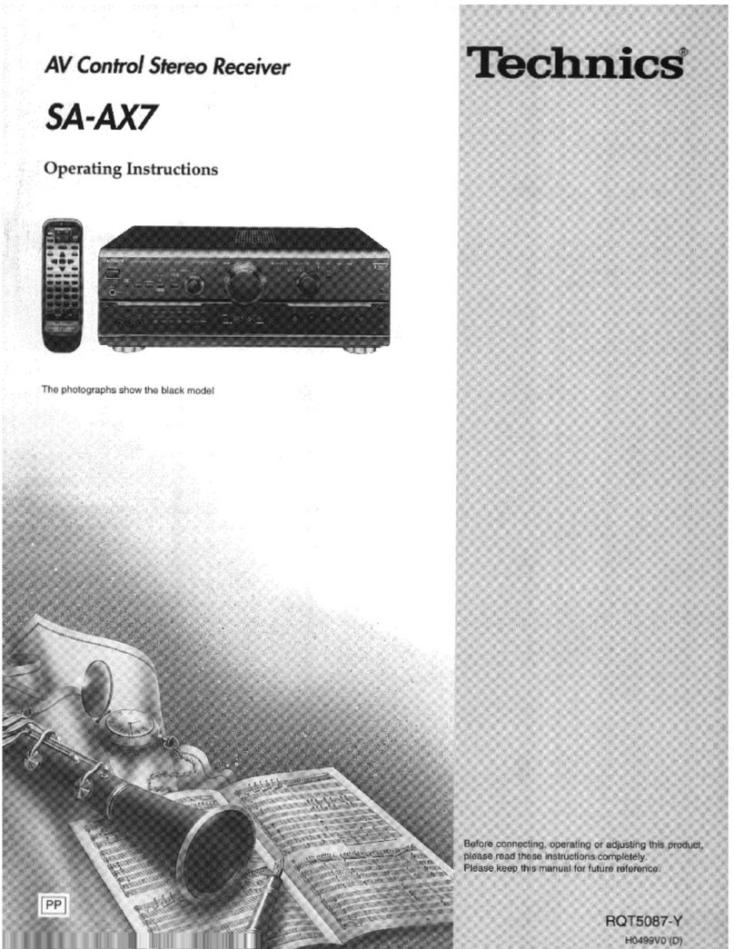
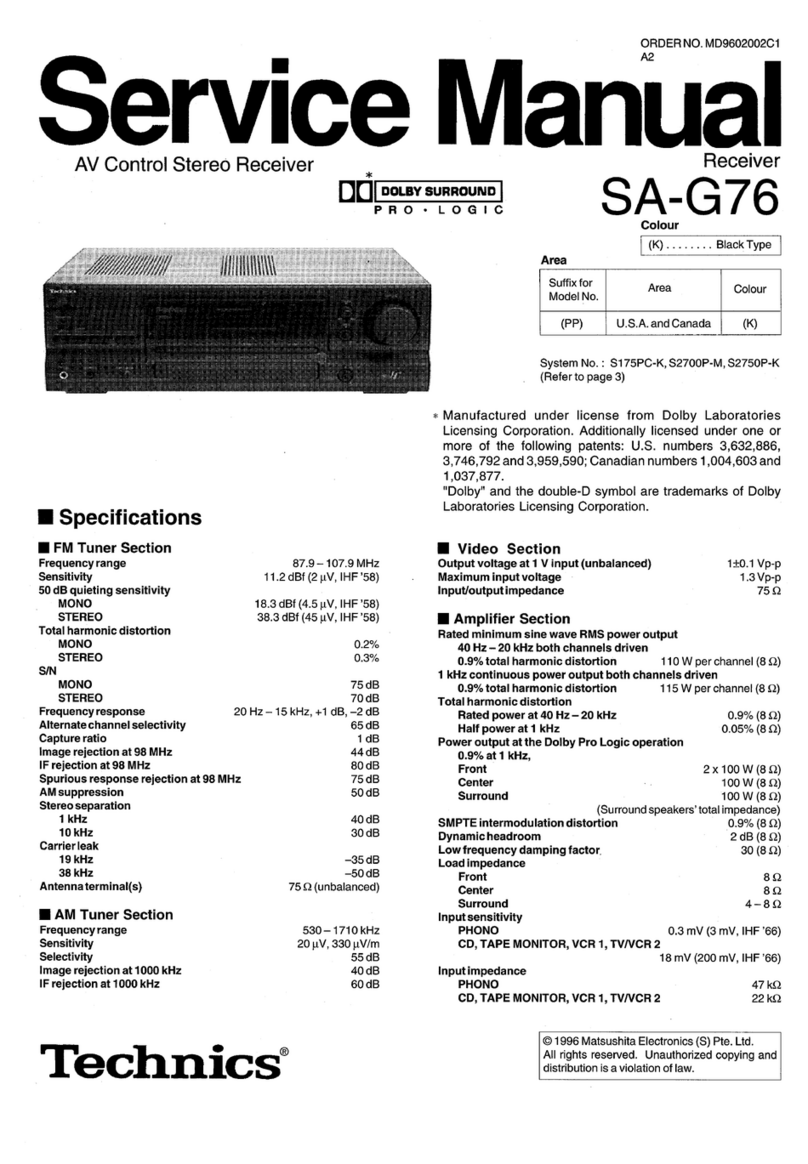
  9. Technics SA-DX950 User manual

Technics SA-DX950 User manual

OrderNo. MD0102029C1
A2
AVControl StereoReceiver
SA-DX950
Color
(K)... Black Type
P... U.S.A.
PC... Canada
SPECIFICATIONS
FMTunerSection
Frequencyrange 87.9-107.9MHz
Sensitivity 11.2dBf(2V, IHF’58)
50 dBquieting sensitivity
MONO 18.3dBf(4.5V, IHF’58)
STEREO 38.3dBf(45 V, IHF’58)
Total harmonicdistortion
MONO 0.2%
STEREO 0.3%
S/N
MONO 73 dB
STEREO 67 dB
Frequencyresponse 20 Hz-15 kHz, +1 dB, -2dB
Alternatechannel selectivity 65 dB
Captureratio 1.5dB
Imagerejection at98 MHz 40 dB
Spuriousresponse rejection at98 MHz 75 dB
AMsuppression 50 dB
Stereo separation
1kHz 40 dB
1
10 kHz 30 dB
Antennaterminal 75 (unbalanced)
AMTunerSection
Frequencyrange 530-1710 kHz
Sensitivity 20 V, 330 V/m
Selectivity 55 dB
IF rejection (at1000 kHz) 50 dB
Video Section
Outputvoltageat1Vinput
(unbalanced) 1±0.1Vp-p
Maximuminputvoltage 1.5Vp-p
Input/outputimpedance 75
AmplifierSection
Rated minimumsinewaveRMSpoweroutput
40 Hz-20 kHzboth channelsdriven
0.9%total harmonicdistortion 100 W perchannel (6 )
1kHzcontinuouspoweroutputboth channelsdriven
0.05%total harmonicdistortion 105 W perchannel (6 )
Total harmonicdistortion
rated powerat40 Hz-20 kHz 0.9%(6 )
halfpowerat1kHz 0.07%(6 )
Powerbandwidth
both channelsdriven, -3dB 10 Hz-70 kHz(6 , 0.9%)
Poweroutputat1kHzeach channel driven
0.9%total harmonicdistortion
Front 2x100 W (6 )
Center 100 W (6 )
Surround 2x100 W (6 )
Lowfrequencydamping factor 30 (6 )
Load impedance
Front
AorB 4-8
Aand B 8
Center 6-8
Surround 6-8
Dynamicheadroom 2dB(6 )
Frequencyresponse
PHONO RIAA standard curve±0.8dB
CD, TAPE, DVD, TV, VCR 10 Hz-70 kHz, ±3dB
Inputsensitivity
PHONO 0.4mV(3mV, IHF’66)
CD, TAPE, DVD, TV, VCR 27 mV(200 mV, IHF’66)
S/N(IHF A)
PHONO 70 dB
CD, TAPE, DVD, TV, VCR 78 dB
DVD6CH 100 dB(IHF A, Rated Power,
S=2 V), 85 dB(94 dB, IHF’66)
Inputimpedance
PHONO 47 k
2
PHONO
47
k
CD, TAPE, DVD, TV, VCR 22 k
Tonecontrols
BASS 50 Hz, +10 to -10 dB
TREBLE 20 kHz, +10 to -10 dB
Subwooferfrequencyresponse (-6dB) 7-200 Hz
Digital input
Optical 2
Coaxicial 1
General
Powersupply AC120 V, 60 Hz
Powerconsumption 410 VA320 W
Dimensions(W xHxD) 430 x158 x375 mm
(16-15/16”x6-7/32”x14-25/32”)
Mass 9.1kg (20.1lb.)
Powerconsumption in standbymode: 1 W
Notes:
1. Specificationsaresubjectto changewithout notice. / Mass and
dimensionsareapproximate.
2. Total harmonicdistortion ismeasuredbythedigital spectrum analyzer.
*Manufactured underlicense fromDolbyLaboratories. “Dolby”,
“Pro Logic”and thedouble-Dsimbol aretrademarks ofDolby
Laboratories.
** Manufactured underlicense fromDigital TheaterSystem. “DTS”
and “DTSDigital Surround”aretrademarks ofDigital Theater
Syatem.
1. SafetyPrecaution
(This“SafetyPrecaution”isappliedonlyinU.S.A.)
1. Beforeservicing, unplug thepowercordtopreventanelectric
shock.
2. Whenreplacing parts, use onlymanufacturer’srecommended
components forsafety.
3. Check thecondition ofthepowercord. Replace ifwearordamage
isevident.
4. Afterservicing, besuretorestoretheleaddress, insulation
3
barriers, insulation papers, shields, etc.
5. Beforereturning theservicedequipmenttothecustomer, besure
tomake thefollowing insulation resistance test topreventthe
customerfrombeing exposedtoashock hazard.
-Insulation Resistance Test
1. Unplug thepowercordand shortthetwoprongsoftheplug witha
jumperwire.
2. Turnon thepowerswitch.
3. Measuretheresistance valuewithohmmeterbetweenthejumper
ACplug and eachexposedmetal cabinet part, suchas screw
heads, antenna, control shafts, handlebrackets, etc. Equipment
withantennaterminalsshouldreadbetween3M and 5.2M toall
exposedparts*. (Fig1) Equipmentwithoutantennaterminals
shouldreadapproximatelyinfinitytoall exposedparts. (Fig2)
*Note:Someexposedparts maybeisolatedfromthechassisby
design. These will readinfinity.
4. Ifthemeasurementisoutsidethespecifiedlimits, thereisa
possibilityofashock hazard. Theequipmentshouldberepaired
and recheckedbeforeitisreturnedtothecustomer.
4
5
2. BeforeRepairand Adjustment
DisconnectACpower, dischargePowerSupplyCapacitorsC1702 through a10 , 5Wresistor
toground. DONOTSHORT-CIRCUITDIRECTLY(withascrewdriverblade, for instance), as this
may destroysolidstatedevices.
Afterrepairsarecompleted, restorepowergraduallyusing avariac, toavoidovercurrent.
Currentconsumption atAC120 V, 60 HzinNOSIGNALmodeshouldbe400~1200 mA.
3. Protection Circuitry
Theprotection circuitrymay have operatedifeitherofthefollowing conditionsarenoticed:
-Nosound isheardwhenthepoweristurnedon.
-Stopsduring aperformance.
Thefunction ofthiscircuitryistopreventcircuitrydamageif, for example, thepositive and
negative speakerconnection wires are“shorted”, or ifspeakersystemswithanimpedance less
thantheindicatedratedimpedance oftheamplifierareused.
Ifthisoccurs, followtheprocedureoutlines below:
1. Turnoff thepower.
2. Determinethecause oftheproblemand correct it.
3. Turnon thepoweronce againafteroneminute.
Note:
Whentheprotection circuitryfunctions, theunitwill notoperateunless thepowerisfirstturned
6
off and thenon again.
4. Accessories ACpowersupplycord... 1pc.
AMLoop AntennaSet/ ... 1set.
FMIndoor Antenna... 1pc.
RemoteControl / Transmitter... 1pc.
5. Front Panel Controls
5.1. FrontPanel
7
5.2. Remote Control
8
6. Operation Checks and MainComponent
Replacement Procedures
“ATTENTIONSERVICER”
Somechassiscomponentsmaybehave sharp edges. Becareful whendiassembling and
servicing.
1. Thissection describes procedures forchecking theoperation of
9
themajorprintedcircuitboardsand replacing themain
components.
2. Forreassemblyafteroperation checks orreplacement, reverse the
respectiveprocedures. / Special reassemblyprocedures are
describedonlywhenrequired.
3. Select itemsfromthefollowing index whenchecks orreplacement
arerequired.
Content
-Checking ProcedureforeachmajorP.C.B.
...................................................................................................................
P.g. 7~9
-MainComponentReplacementProcedures
1. ReplacementofthePowerICand Regulator
Transistor.............................................................................................
P.g. 10
2. Installation ofthebottomcoverafter
replacement...........................................................
............................................ P.g. 11
6.1. Checking ProcedureforeachmajorP.C.B.
Step1&2Unscrewand remove top cabinetas shown.
10
Step3Remove all thescrews.
Step4Release theconnector CN904B.
11
Step5Remove all thescrews.
Step6&7Remove all thescrews.
12
Step8Remove all theSelector knob and Volumeknob. Unscrewthenutand remove all the
Selector ring and Volumering.
Step9Remove all thescrewsand therearpanel inthedirection ofthearrow.
Step10 Release theconnectorsCN702 and CN1000A. Pull up theDigital P.C.B. as shown.
13
Step11, 12 &13 Remove all thescrews.
Reconnectall wires and connectorstotestall P.C.B..
6.2. MainComponentReplacementProcedures
6.2.1. ReplacementofthePowerICand Regulator Transistor
Step1Remove thetop cabinet.
14
Step2Cutthejointsas shownbelow. (6joints)
15
Step3Foldthejoints. (6joints)
Step4DesoldertheterminalsofPowerICand Regulator Transistor.
16
Step5Remove all thescrews.
6.2.2. Installation ofthebottomcoverafterreplacement
17
Step1Upsetthebottom cover.
Step2Align theribsofbottom coverintothebugs.
Step3Preparethescrewstofixthebottom cover.
7. Type Illustrations of ICs, Transistors&Diodes
8. Terminal Functions of ICs
-IC901 (C2BBGF000262) MICRO COMPUTER
18
Pin
No. Mark I/O Function
1~2 KEY1~KEY2 I Key Input1~2
3RDS_CLK - RDS DataICCLOCK
4 RDS_DO - RDS DataIC-DATAOUT
5 RDS_DI - RDS DataIC-DATAIN
6RDS_CE - Control ofRDS IC(Not
used, open)
7THERM/OVLD1 I Thermal/Overloadinput1
8THERM/OVLD2 I Thermal/Overloadinput2
9 SD I SDsignal detectinput
10 IFDATA I IFDATAinput
11 TNR_CE O Tunercontrol (CE)chip
enablesignal
12 SFC_ENCD_1 I SFCmodeencoderinput1
13 SFC_ENCD_2 I SFCmodeencoderinput2
14 TC9482_CLK O Volumecontrol -CLK
15 TC9482_DT O Volumecontrol -DT
16 TC9482_ST O Volumecontrol -ST
17 CNVSS - -
18 RESET - Resetdetectterminal
19 DSP_PASS/
DSP_OFF ODSP signal selector
20 MOS_FET_LED OMOS FETLED
21 VSS I Ground
22 XIN I Crystal oscillator terminal
(4MHz)
23 XOUT O Crystal oscillator terminal
(4MHz)
24 VCC I Powersupplyterminal
25 VOL_ENCD_1 O Volumeencoderinput1
26 VOL_ENCD_2 O Volumeencoderinput2
27 CS4226_CDOUT I CS4226 serial datainput
28 CS4226_CS I CS4226 chipselector
29 CS4226_OVLERR I CS4226 overloaderror
input
30 CS49326_INTREQ ICS49326 inputrequest
31 REMOTE I Remotecontrol terminal
32 HOLD I Blackoutdetection
terminal
33 FRONT_VCR I Encoderofsurround
modeselector input1
34 SEL_ENCD_1 I Selector encoderfor input
1
35 SEL_ENCD_2 I Selector encoderfor input
2
36
TAPE_LED
O
Tape
Selector
LED
19
36
TAPE_LED
O
Tape
Selector
LED
37 VCR_LED O VCR Selector LED
38 TV_LED O TV Selector LED
39 DVD_LED O DVDSelector LED
40 CD_LED O CD Selector LED
41 TUNER_LED O TUNERSelector LED
42 PHONO_LED O PHONOSelector LED
43 DIGITAL_LED O DIGITALINPUTLED
44 DVD_6CH_LED ODVD6CH LED
45 LIMITTER O Powerlimittercontrol
output
46 TC916x_STB O Selector/Tuner(CK) clock
signal
47 TC916x_TNR_CKOSelector/Tuner/DVD6CH
SW-CK
48 TC916x_TNR_DTOSelector/Tuner/DVD6CH
SW-DT
49 S/CSP O Surround/Centerspeaker
control output
50 SP B O SpeakerBcontrol output
51 SP A O SpeakerAcontrol output
52 RELAY O Relay control output
53 AF_MUTE O Muting control output
54 SUBW_MUTE O Subwoofermuting
55 WAKE_LED - Wake up timerLED(Not
used, open)
56 VCR_MUTE O VCR RECORD MUTE
57~59 NOTUSED - NOTUSED
60~78 SEG19~SEG1 O FL segmentsignal output
79~88 DEG1~DEG10 O FL digitsignal output
89 VEE - Powersupplyfor FL driver
90CS49326_SCDOUT
O CS49326 serial data
poweroutput
91 CS49326_CDIN I CS49326 serial data
powerinput
92 CS49326_CCLK ICS49326 serial clock
93 CS49326_CS I CS49326 chipselector
94 CS4226_RESET ICS4226 reset
95 CS49326_RESET ICS49326 reset
96 INIT_IN I Diodeinputintial settings
97 AVSS - Ground
98 VREF - Reference voltage
99 VIDEO_B O Videoselector control
outputB
100 VIDEO_A O Videoselector control
outputA
20

Other Technics Stereo Receiver manuals
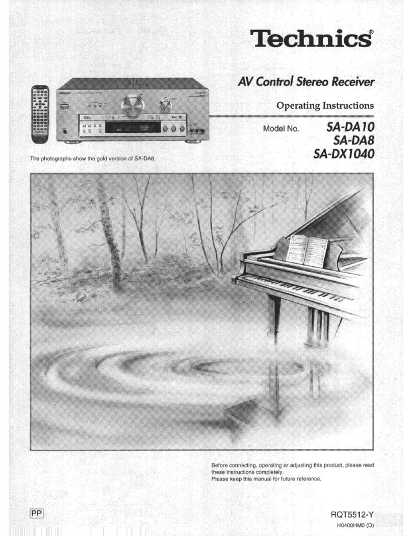
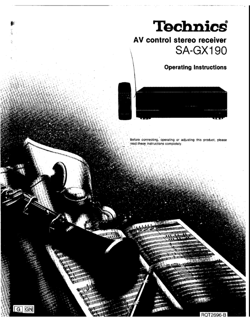
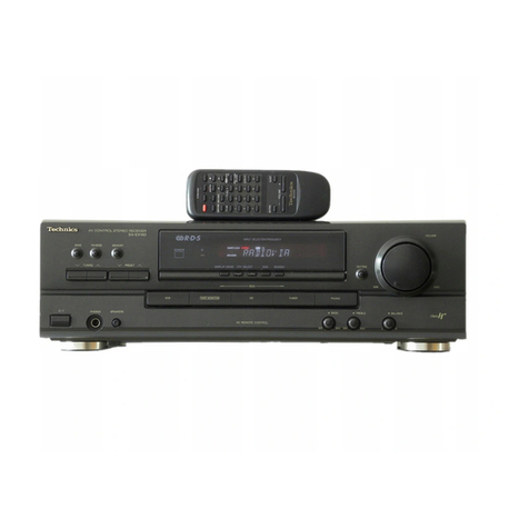
Technics SA-EX100 User manual

Technics

Technics SA-EX100 User manual

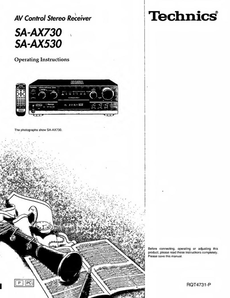
Technics SA-AX720 User manual

Technics

Technics SA-AX720 User manual

Technics SA-EX300 User manual

Technics

Technics SA-EX300 User manual

Technics SA-GX170 User manual

Technics

Technics SA-GX170 User manual

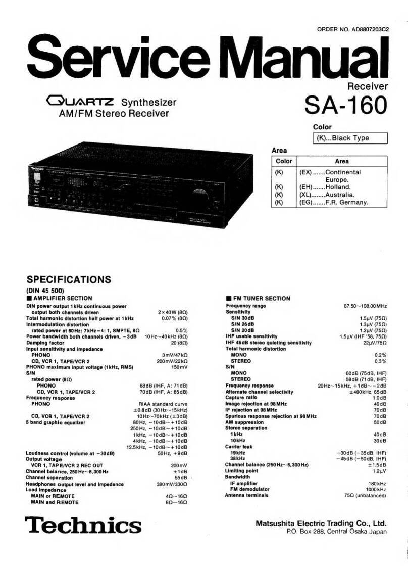
Technics SA-EX100 User manual

Technics

Technics SA-EX100 User manual

Technics SA-GX670 User manual

Technics

Technics SA-GX670 User manual

Technics SAEX110 - RECEIVER User manual

Technics

Technics SAEX110 - RECEIVER User manual

Technics QUARTZ SA-R330 User manual

Technics

Technics QUARTZ SA-R330 User manual

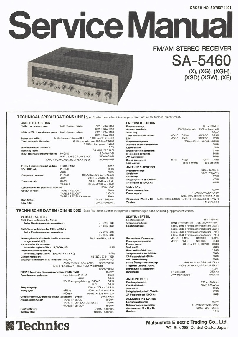
Technics QUARTZ SA-160 User manual

Technics

Technics QUARTZ SA-160 User manual

Technics SA-EX510; SA-EX410; SA-EX310 User manual

Technics

Technics SA-EX510; SA-EX410; SA-EX310 User manual

Technics SAEX140 - RECEIVER User manual
Technics

Technics SAEX140 - RECEIVER User manual

Technics SH-AC500D User manual

Technics

Technics SH-AC500D User manual

Technics SA-EX120 User manual

Technics

Technics SA-EX120 User manual

Technics SAAX6 - RECEIVER User manual

Technics

Technics SAAX6 - RECEIVER User manual

Technics SA-GX550 User manual

Technics

Technics SA-GX550 User manual

Technics SA-EX120 User manual

Technics

Technics SA-EX120 User manual

Technics SA-EX700 User manual

Technics

Technics SA-EX700 User manual

Technics SA-EX510; SA-EX410; SA-EX310 User manual

Technics

Technics SA-EX510; SA-EX410; SA-EX310 User manual

Technics SA-AX7 User manual

Technics

Technics SA-AX7 User manual

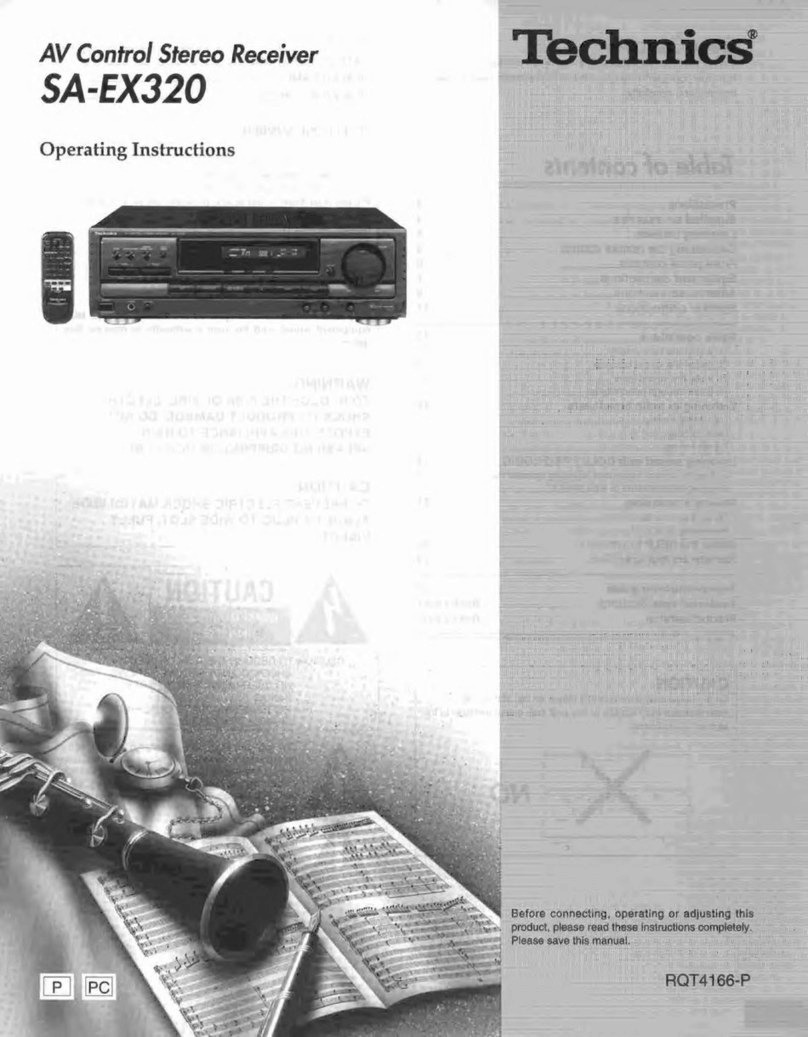
Technics SA-EX320 User manual

Technics

Technics SA-EX320 User manual
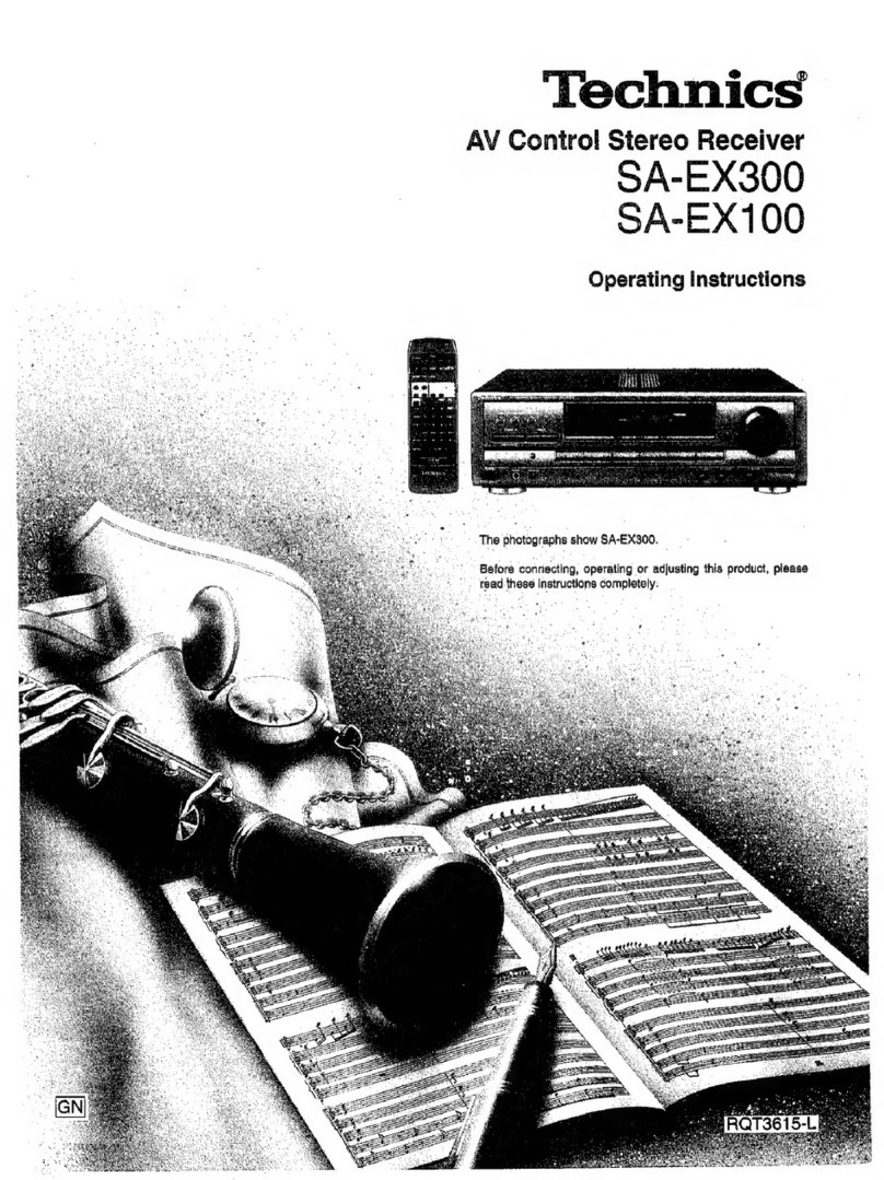
Technics SAAX6 - RECEIVER User manual

Technics

Technics SAAX6 - RECEIVER User manual

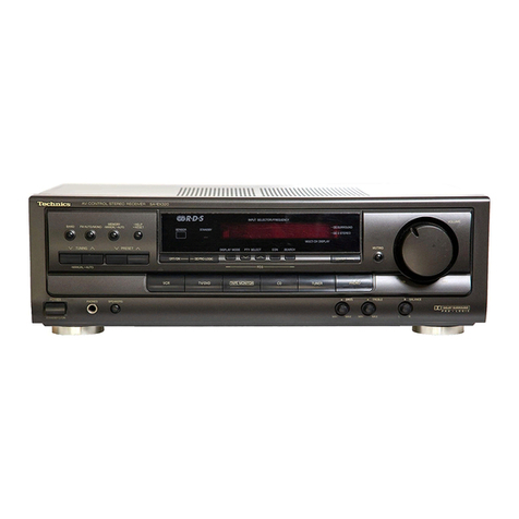
Technics SADX930 - RECEIVER User manual
Technics

Technics SADX930 - RECEIVER User manual

Technics SA-GX170 User manual

Technics

Technics SA-GX170 User manual

Technics SA-G76 User manual

Technics

Technics SA-G76 User manual

Popular Stereo Receiver manuals by other brands

Denon AVR-S670H owner's manual

Denon

Denon AVR-S670H owner's manual

Kenwood KR-V5580 instruction manual

Kenwood

Kenwood KR-V5580 instruction manual

Sony STR-GX5ES Service manual

Sony

Sony STR-GX5ES Service manual

Yamaha Aventage RX-A3040 Easy setup guide

Yamaha

Yamaha Aventage RX-A3040 Easy setup guide

Yamaha RX-V3900 Service manual

Yamaha

Yamaha RX-V3900 Service manual

Marantz SR-3001 user guide

Marantz

Marantz SR-3001 user guide

PULSE+ SRA-160USB user manual

PULSE+

PULSE+ SRA-160USB user manual

Pioneer SX-V90 operating instructions

Pioneer

Pioneer SX-V90 operating instructions

Pioneer SX-2900 operating instructions

Pioneer

Pioneer SX-2900 operating instructions

Yamaha HTR-5630RDS owner's manual

Yamaha

Yamaha HTR-5630RDS owner's manual

Yamaha R-2000 Service manual

Yamaha

Yamaha R-2000 Service manual

Yamaha TR-5630RDS owner's manual

Yamaha

Yamaha TR-5630RDS owner's manual

JVC R-S7 Service manual

JVC

JVC R-S7 Service manual

Jensen CDX3119 Installation & owner's manual

Jensen

Jensen CDX3119 Installation & owner's manual

Harman Kardon HK880VXI instruction manual

Harman Kardon

Harman Kardon HK880VXI instruction manual

Onkyo TX-8211 instruction manual

Onkyo

Onkyo TX-8211 instruction manual

Philips LX710/01 user manual

Philips

Philips LX710/01 user manual

NAD T755 owner's manual

NAD

NAD T755 owner's manual

manuals.online logo
manuals.online logoBrands
  • About & Mission
  • Contact us
  • Privacy Policy
  • Terms and Conditions

Copyright 2025 Manuals.Online. All Rights Reserved.