manuals.online logo
Brands
  1. Home
  2. •
  3. Brands
  4. •
  5. Technics
  6. •
  7. Tuner
  8. •
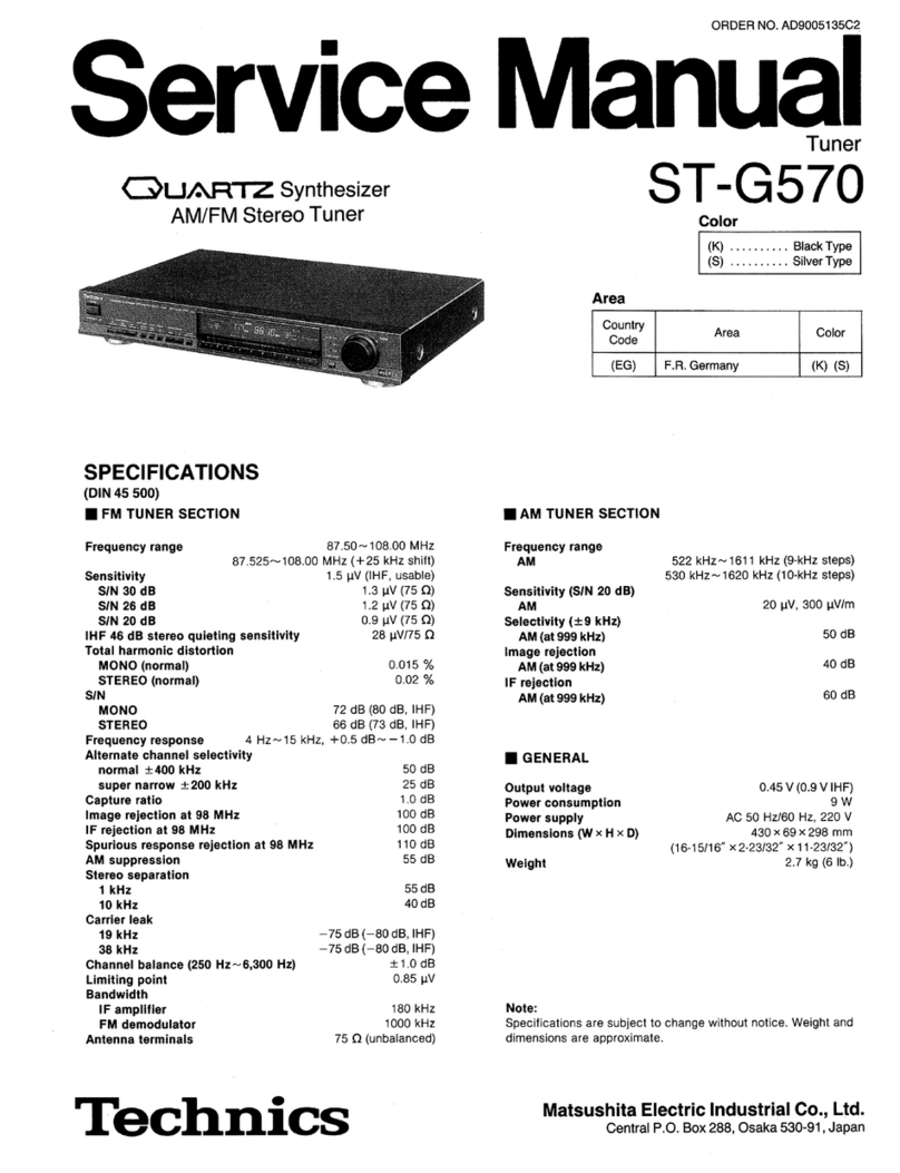
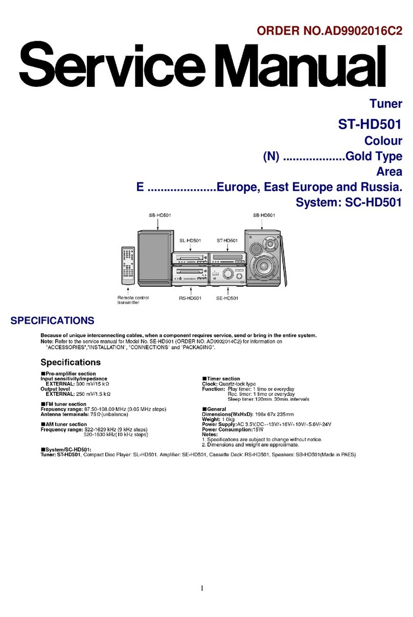
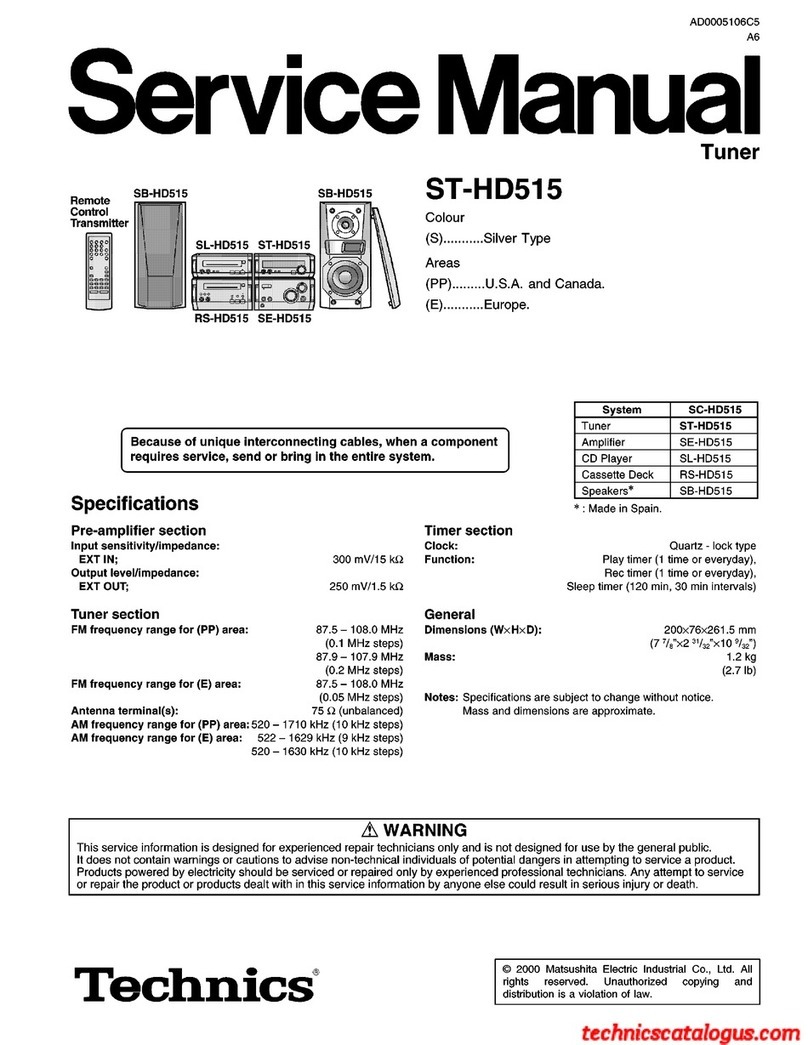
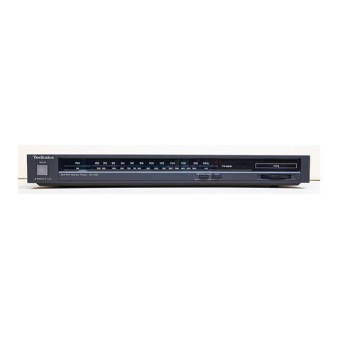
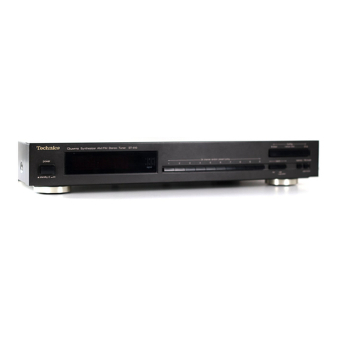
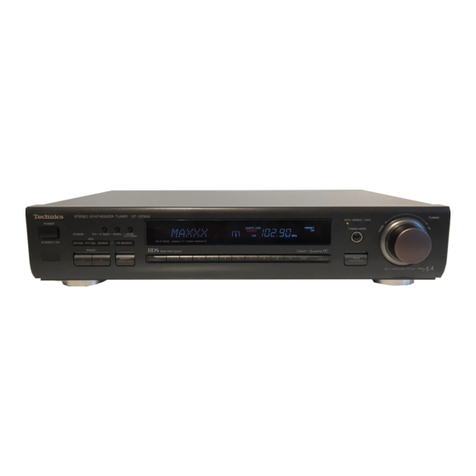
  9. Technics QUARTZ ST-Z400L User manual

Technics QUARTZ ST-Z400L User manual

Other Technics Tuner manuals

Technics ST-S2L User manual

Technics

Technics ST-S2L User manual

Technics QUARTZ ST-X999 User manual

Technics

Technics QUARTZ ST-X999 User manual

Technics ST-G560L User manual

Technics

Technics ST-G560L User manual

Technics ST-8055 User manual

Technics

Technics ST-8055 User manual

Technics Quartz ST-G45AL User manual

Technics

Technics Quartz ST-G45AL User manual

Technics SA-EH750 User manual

Technics

Technics SA-EH750 User manual

Technics ST-GT630 User manual

Technics

Technics ST-GT630 User manual

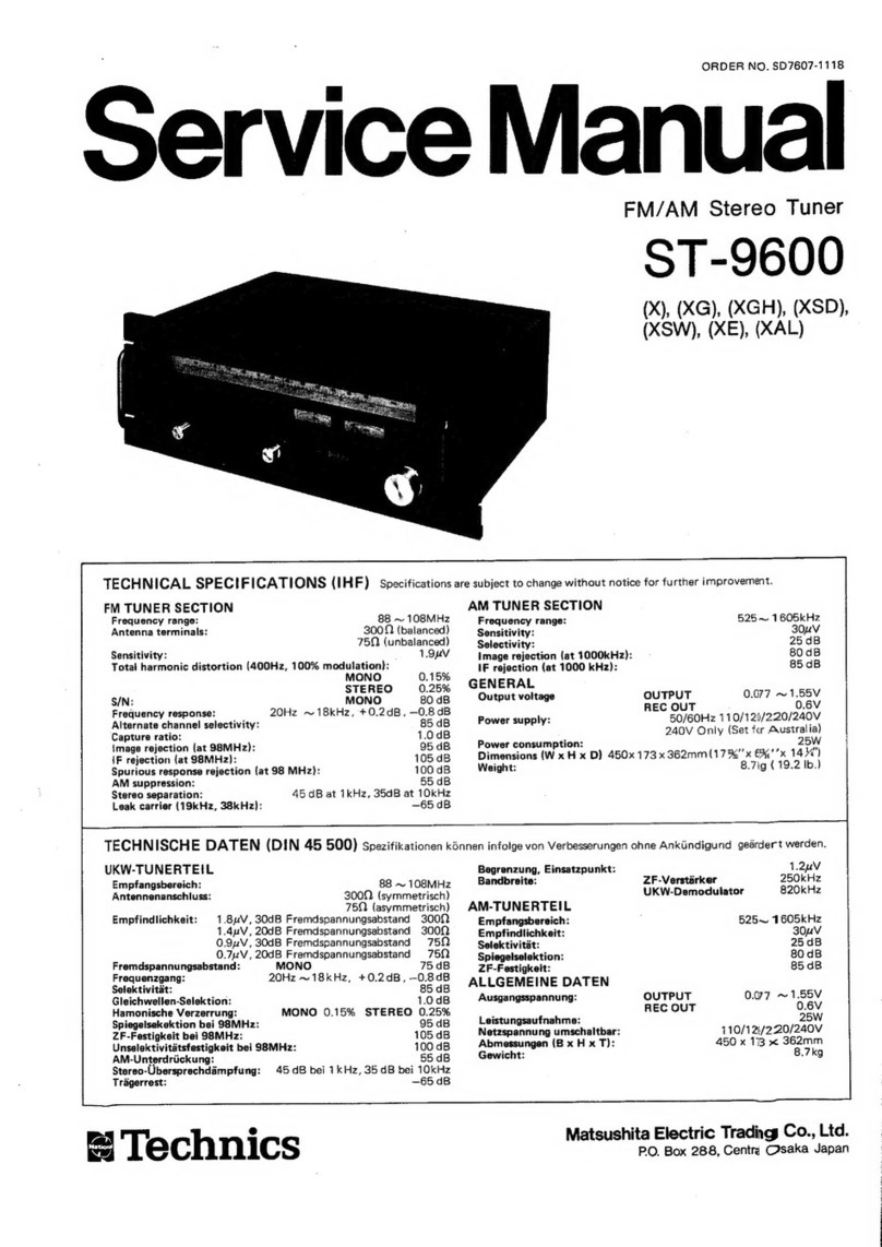
Technics ST-9600 User manual

Technics

Technics ST-9600 User manual

Technics ST-GT650 User manual

Technics

Technics ST-GT650 User manual

Technics SA-EH760 User manual

Technics

Technics SA-EH760 User manual

Technics ST-8080 User manual

Technics

Technics ST-8080 User manual

Technics ST-CA01 User manual

Technics

Technics ST-CA01 User manual

Technics ST-CH505 User manual

Technics

Technics ST-CH505 User manual

Technics ST-8044 User manual

Technics

Technics ST-8044 User manual

Technics Quartz ST-G7 User manual

Technics

Technics Quartz ST-G7 User manual

Technics ST-300 User manual

Technics

Technics ST-300 User manual

Technics ST-X302L User manual

Technics

Technics ST-X302L User manual

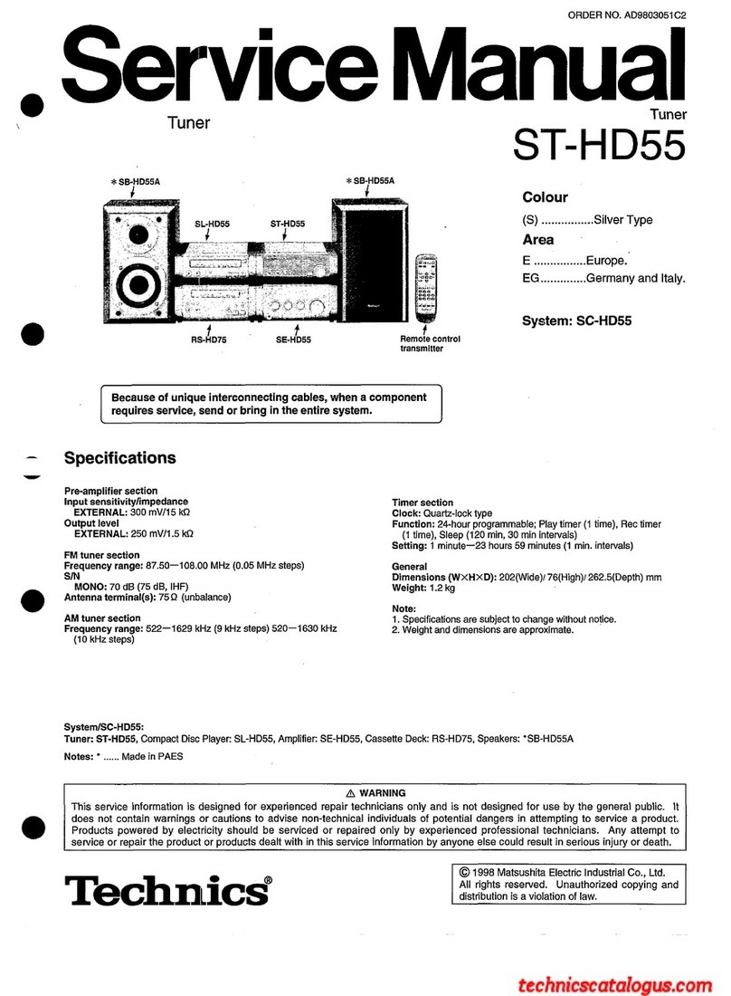
Technics ST-HD55 User manual

Technics

Technics ST-HD55 User manual

Technics ST-G570 User manual

Technics

Technics ST-G570 User manual

Technics ST-HD51 User manual

Technics

Technics ST-HD51 User manual

Technics ST-HD515 User manual

Technics

Technics ST-HD515 User manual

Technics ST-S4T User manual

Technics

Technics ST-S4T User manual

Technics SA-DV290EE User manual

Technics

Technics SA-DV290EE User manual

Technics ST-HD505 User manual

Technics

Technics ST-HD505 User manual

Popular Tuner manuals by other brands

Arcam DT91 Handbook

Arcam

Arcam DT91 Handbook

HDHomeRun 20121008 installation instructions

HDHomeRun

HDHomeRun 20121008 installation instructions

Eico HFT-92 instruction manual

Eico

Eico HFT-92 instruction manual

MFJ MFJ-928 instruction manual

MFJ

MFJ MFJ-928 instruction manual

Teac T-1D Service manual

Teac

Teac T-1D Service manual

NAD C 445 owner's manual

NAD

NAD C 445 owner's manual

Sony ST-SA5ES operating instructions

Sony

Sony ST-SA5ES operating instructions

Pioneer GEX-P700DAB Operation manual

Pioneer

Pioneer GEX-P700DAB Operation manual

Sirius Satellite Radio SC-FM1 user guide

Sirius Satellite Radio

Sirius Satellite Radio SC-FM1 user guide

Antique Automobile Radio 283501B Installation and operating instructions

Antique Automobile Radio

Antique Automobile Radio 283501B Installation and operating instructions

Sanyo FMT M15L Service manual

Sanyo

Sanyo FMT M15L Service manual

Monacor PA-1200R instruction manual

Monacor

Monacor PA-1200R instruction manual

Manhattan 176156 user manual

Manhattan

Manhattan 176156 user manual

Marantz ST-15S1 user guide

Marantz

Marantz ST-15S1 user guide

Korg HA-40 owner's manual

Korg

Korg HA-40 owner's manual

Pioneer XC-IS21T Service manual

Pioneer

Pioneer XC-IS21T Service manual

Harman Kardon TU915 Technical manual

Harman Kardon

Harman Kardon TU915 Technical manual

Tunersys WS16 1 quick start guide

Tunersys

Tunersys WS16 1 quick start guide

manuals.online logo
manuals.online logoBrands
  • About & Mission
  • Contact us
  • Privacy Policy
  • Terms and Conditions

Copyright 2025 Manuals.Online. All Rights Reserved.

ORDER
NO.
HAD84072864C2
Service
Manual
Tuner
CYUARTZ
Synthesizer
FM/MW/LW
Stereo
Tuner
ST-Z400L
SPECIFICATION
(DIN
45
500)
@
FM
TUNER
SECTION
Frequency
range
Sensitivity
S/N
30
dB
S/N
26
dB
S/N
20
dB
IHF
usable
sensitivity
IHF
46
dB
stereo
quieting
sensitivity
Total
harmonic
distortion
MONO
STEREO
S/N
MONO
STEREO
Frequency
response
Alternate
channel
selectivity
normal
+400
kHz
Capture
ratio
Image
rejection
at
98
MHz
IF
rejection
at
98
MHz
Spurious
response
rejection
at
98
MHz
AM
suppression
Stereo
separation
1
kHz
10
kHz
Carrier
leak
19
kHz
38
kHz
Channel
balance
(250
Hz~6,300
Hz)
Limiting
point
Bandwidth
IF
amplifier
FM
demodulator
Technics
87.50~108.00
MHz
1.0
pV
(750)
0.9
pV
(759)
0.8
pV
(759)
0.95
pV
(IHF
’58)
22
uV/75Q
0.15%
0.3%
69
dB
(75
dB,
IHF)
64
dB
(70
dB,
IHF)
5
Hz~18
kHz,
+0.5
dB~
—-1.5
dB
60
dB
1.0
dB
55
dB
90
dB
80
dB
55
dB
45
dB
30
dB
~40
dB
(—45
dB,
IHF)
—40
dB
(—45
dB,
IHF)
+1
dB
1.0
uv
180
kHz
1000
kHz
Color
(K)...Black
Type
(S)...Silver
Type
Color
Area
(K)(S)
|
[EX]...Scandinavia
and
Switzerland.
(K)(S)
|
[EK]...United
Kingdom
(S)
|
[EF]...
France
(K)(S)
|
[EB]...Beigium
Antenna
terminals
For
United
Kingdom
For
others
@
AM
TUNER
SECTION
Frequency
range
MW
522~1611
kHz
LW
155~353
kHz
153~351
kHz
(-2
kHz
shift)
75Q(unbalanced),
300Q(balancea)
75Q
(unbalanced)
Sensitivity
(S/N
20
dB)
MW
at
999
kHz
20
pV,
300
wV/m
LW
at
254
kHz
100
pV
Selectivity
(+9
kHz)
MW
at
999
kHz
55
dB
LW
at
254
kHz
55
dB
Image
rejection
MW
at
999
kHz
40
dB
LW
at
254
kHz
40
dB
IF
rejection
MW
at
999
kHz
60
dB
LW
at
254
kHz
50
dB
M@
GENERAL
Output
voltage
0.4V
Power
consumption
SW
Power
supply
For
United
Kingdom
For
continental
Europe
Dimensions
(WxHxD)
AC
50
Hz/60
Hz,
240V
AC
50
Hz/60
Hz,
220V
430
x
53
X
240
mm
(16-15/16”
X
2-3/32”
X
9-7/16")
Weight
2.1
kg,
(4.6
Ib.)
(Specifications
are
subject
to
change
without
notice
for
further
improvement.)
Matsushita
Electric
Trading
Co.,
Ltd.
P.O.
Box
288,
Central
Osaka
Japan
5
ey
2:
tole)
&
m@
CONTENTS
Page
Page
LOCATION
OF
CONTROLS
............02
00
eee
eee
2
FUNCTION
OF
TERMINAL
(PLL
controller
1C901)
.....
..
10
AM
LOOP
ANTENNA...
22.2...
ee
eee
ee ee
es
2
BLOCK
DIAGRAM.
.............2205-
mice
eae
eee
11,12
HOW
TO
PRESET
RADIO
BROAD-
SCHEMATIC
DIAGRAM
...........-..0020000.
13
~15
CAST
FREQUENCIES.
............
00002005
3,4
LIQUID
CRISTAL
DISPLAY
(LCD)................4.
16
DISASSEMBLY
INSTRUCTION...
......0.00
02a
eee
5
RESISTORS
AND
CAPACITORS
............02000%
7
BEFORE
REPAIR
....
0.0...
ee
ee
ee
ns
5
REPLACEMENT
PARTS
LIST.
..........
2.0200
eae
18
MEASUREMENTS
AND
ADJUSTMENTS
............
6,7
EXPLODED
VIEW...
1...
.
eee
eee
ee
es
19,
20
CIRCUIT
BOARD
AND
WIRING
CONNECTION
DIAGRAM
............0008005
8,9
m@
LOCATION
OF
CONTROLS
Memory
indicator
Quartz
lock/signal
indicator
Digital
Frequency
display
Preset-tuning
buttons
FM
stereo
indicator
FM
mode
selector
(auto/mono)
(
HL
stand
by,
=
on)
(FM)
Channel
display
—_
Band
selectors]
L
(up)
(MW/LW)
|
toning
For
LW
broadcasts:
(down)
This
switch
is
also
used
to
shift
the
reception
frequency
of
the
unit
in
accordance
with
the
transmission
frequency
of
the
broadcasting
station.
When
this
button
is
pressed
slightly
longer,
the
reception
frequency
decreases
by
0.002
MHz
(2
kHz).
So,
for
example,
to
receive
153
kHz,
tune
to
155
kHz,
and
then
press
this
button.
In
order
to
return
to
the
original
frequency
indication,
press
this
button
again.
AM
loop
antenna
terminal
Memory
AM
antenna
terminal
__
routout
terminal
co
aurPur
CONTROL;
r
,
Fi
fhe
re)
8
bd
(0
©
09
WARNING
DANGEROUS
VOLTAGE
INSIDE
Oem
——~-
AC
inlet
s
CAUTION
09
NCT
REMOVE
SCREWS
rs
i
‘i
HAN,
oT
o .
FM
antenna
terminal
(3002)
[EK]
area
only
aN
ta
i
s
Control
input
terminal
FM
antenna
terminal
(75Q)
@
The
power
supply
for
this
unit
varied
depending
upon
the
areas.
Also,
the
parts
used
for
power
supply
are
different.
So,
refer
to
the
circuit
diagram
and
the
replacement
parts
list;
*
220V
(50/60
Hz)
for
Continental
Europe.
*
240V
(50/60
Hz)
for
United
Kingdom.
m@
AM
LOOP
ANTENNA
When
the
AM
loop
antenna
is
connected
to
the
rear
panel,
place
it
as
far
away
from
the
set
as
possible
to
improve
the
sensitivity.
Precautions
for
attachment
®@
Do
not
place
near
a
metal
surface
®
Do
not
lay
flat
Metal
surface
_
A
CQUARTZ
Synthesizer
ST
ZA400L
FM/MW/LW
Stereo
Tuner
=
®
This
booklet
includes
the
specifications
and
adjustment
of
Model
ST-Z400L
(Order
No.
HAD84072864C2)
written
in
German
and
French.
@
File
this
booklet
together
with
the
service
manual
of
Model
ST-Z400L.
®
Dieses
Bichlein
umfa&t
die
technischen
Daten
und
Justierungsanleitungen
von
Model!
ST-Z400L
(Bestell
Nr.
HAD84072864C2)
in
den
Sprachen
Deutsch
und
Franzésisch.
®@
Bewahren
Sie
dieses
Biichlein
zusammen
mit
dem
Service-Handbuch
von
Modell
ST-Z400L
auf.
@
Cette
brochure
comprend
les
spécifications
et
la
mise
au
point
du
Modéle
ST-Z400L
(N°
d’Ordre
HAD84072864C2)
écrites
en
allenmand
et
en
francais.
®@
Classer
cette
brochure
en
meme
temps
qu’avec
le
manuel
de
service
du
Modele
ST-Z400L.
DEUTSCH
m
TECHNISCHE
DATEN
(DIN
45
500)
@
UKW-TUNERTEIL
@
MW-TUNERTEIL
Wellenbereich
87,50
~
108,00
MHz
Wellenbereiche
Eingangsemptindlichkeit
MW
522
~
1611
kHz
S/R
30
dB
1,0
wv
(75
Q)
LW
155
~
353
kHz
S/R
26
dB
0,9
pV
(75
Q)
153~351
kHz
(—2
kHz
shift)
S/R
20
dB
0,8
wV
(75
Q)
Eingangsempfindlichkeit
(S/R
20
dB)
Nutzempfindlichkeit
nach
IHF
0,95
pV
(nach
IHF
'58)
MW
bei
999
kHz
20
pV,
300
pV/m
Stereoumschaltschwelle
bei
46
dB
nach
|HF
22
wV/75
QO
LW
bei
254
kHz
100
uv
Gesamtklirrfaktor
Trennscharfe
(+9
kHz)
Mono
0,15%
MW
bei
999
kHz
55
dB
Stereo
0,3%
LW
bei
254
kHz
55
dB
Gerauschabstand
Spiegelfrequenz-Dampfung
Mono
69
dB
(75
dB
nach
IHF)
MW
bei
999
kHz
40
dB
Stereo
64
dB
(70
dB
nach
IHF)
LW
bei
254
kHz
40
dB
Frequenzgang
5
Hz
~
18
kHz
(+0,5
dB
~
—1,5
dB)
ZF-Damptung
Trennschirfe
bei
Stérsender
MW
bei
999
kHz
60
dB
normal
+400
kHz
60
dB
LW
bei
254
kHz
50
dB
Einfangverhaltnis
1,0
dB
;
Spiegelfrequenz-Dampfung
bei
98
MHz
55
dB
M@
ALLGEMEINE
DATEN
ZF-Dampfung
bei
98
MHz
90
dB
Ansprechdampfung
auf
Nebenfrequenzen
bei
98
MHz
80
dB
Ausgangsspannung
04V
MW-Unterdriickung
55
dB
Leistungsaufnahme
ow
Ubersprechdémpfung
Netzspannung
1
kHz
45
dB
Fiir
Kontinentaleuropa
Wechselstrom
50
Hz/60
Hz,
220V
10
kHz
30
dB
Abmessungen
(BXHXT)
430
x
53
X
240
mm
Tragerrest
Gewicht
2,1kg
19
kHz
—40
dB
(—45
dB
nach
IHF)
38
kHz
—40
dB
(—45
dB
nach
IHF)
¢ :
-
.
Kanalabweichung
(250
Hz
~
6300
Hz)
+1
dB
(Die
technischen
Daten
kdnnen
infoige
von
Verbesserungen
Begrenzereinsatz
1,0
pV
ohne
Ankiindigung
geandert
werden.)
Bandbreite
ZF-Verstarker
180
kHz
UKW-Demodulator
1000
kHz
AntennenanschluB
75
Q
(unsymmetrisch)
—1—_—
DEUTSCH
-
M@
MESSUNGEN
UND
JUSTIERUNGEN
Anmerkung:
Die
AM-OSC-Spule
(L203),
AM
ZFT
(T7201)
und
LW
ant.
Spule
(L251)
sind
bereits
justiert
und
bendtigen
daher
keine
Justierung.
AM
(MW)-EINSTELLUNG
Einstetlungen
und
zu
benutzende
Gerate
.
Elektronisches
Voltmeter
fiir
Wechsel-
und
Gleichstrom
(EVM).
.
AM
(MW)-MeRsender
(AM-SG).
.
FM/AM-Wahlschalter
in
die
“MW/LW'’-Position
stellen.
(9
kHz-Schritt)
.
Netzspannung
auf
ihrem
Sollwert
halten.
5.
Der
Ausgang
des
Mef&senders
darf
nicht
hGher
sein
als
unbedingt
notwendig
fur
eine
gute
Ablesung.
.
Einen
nichtmetallischen
Schraubenzieher
fiir
die
Einstellungen
verwenden,
ANZEIGE-
FREQUENZ
OURCH
VOR-
EINSTELLUNG
AM
(MW)-MESSENDER
ANSCHLUSS
FREQUENZ
VORBEREITUNG
ABGLEICHS-
PUNKTE
ABGLEICHSVERFAHREN
AM
(MW)-HF-ABGLEICH
*Bandwahischalter
in
die
‘““MW’’-Position
stellen.
612
kHz
(400
Hz
Modulat.,
30%)
1]
AM-MO
iiber
200
pF-
612
kHz
Kondensator
an
den
AM-AntennenanschluR
anschlieRen.
Erdung
an
chassis.
(Schwacher
2
Ejingang.)
1503
kHz
anschlieRen,
(400
Hz
Modulat.,
30%)
1503
kHz
is
LW-HF-ABGLEICH
Wechselstrom-Voltmeter
oder
Oszillograph
Uber
den
Ausgang
‘‘OUTPUT’”’
.
Auf
max,
Ausgang
abgleichen,
.
Den
Kern
von
L202
mit
einem
Schraubendreher
justieren.
L202
(Ant.
Spule)
.
Auf
max.
Ausgang
abgleichen.
.
Die
Schritte
(1)
und
(2)
wiederholen,
bis
die
Frequenz
genau
mit
der
Skalenanzeige
ubereinstimmt,
CT201
(Ant,
Trimmer)
*Bandwahlschalter
in
die
‘‘LW’'-Position
stellen.
155
kHz
3
(400Hz
AM-MO
itiber
200
pF-
Modulat.,
Kondensator
an
den
30%)
AM-Antennenanschlu
anschlieRen.
(Schwacher
Eingang.)
353
kHz
4
(400
Hz
Modulat.,
30%
FM
(UKW)-EINSTELLUNG
Einstellungen
und
zu
benutzende
Gerate
UKW-MeRsender
(FM-SG)
Stereo-Modulator
Oszillograph
Elektronische
Voltmeter
fiir
Wechsel-
und
Gleichstrom
(EVM).
Signalfrequenzmesser
(meRbar
fiir
19
KHz
und
108
MHz).
TiefpaRfilter
(fc
=
15
kHz
~
19
kHz).
FM/AM-Wahlschalter
in
die
’FM”-Position
stellen.
Den
UKW-Betriebsartenschalter
in
die
“‘“mono’’-Position
stellen,
155
kHz
anschlieRen.
353 kHz
ONOOBWNH>
*
Wechselstrom-Voltmeter
oder
Oszillograph
uber
den
Ausgang
“OUTPUT”
.
Auf
max.
Ausgang
abgleichen.
.
Den
Kern
von
L252
mit
einem
Schraubendreher
justieren.
L252
(Osz.-Spule)
.
Auf
max.
Ausgang
abgleichen.
.
Die
Schritte
(3)
und
(4)
wiederholen,
bis
die
Frequenz
genau
mit
der
Skalenanzeige
Ubereinstimmt.
CT251
(LW
Ant.-
Trimmer)
Vorbereitung
am
UKW-Messender
(FM-SG)
.
SG-Ausgang
tber
75-Ohm-U
KW-Kunstantenne
an
den
Antenneneingang
des
Gerates
anschlieen.
,
Der
normale
Eingang
des
Gerates
betrat
60
dB
(1
mV),
400
Hz,
100%
Modulation,
Wegen
Verwendung
der
Kunstantenne
mu
ber
Signalausgang
12
dB
(4yV)
plus
(ZHF)
sein:
d.h.
beim
Eingang
von
60
dB
(1
mV)
soll
der
Signalausgang
72
dB
4
mV)
sein.)
ANZEIGE-
FREQUENZ
DURCH
VOR-
EINSTELLUNG
FM
(UKW)-MESSENDER
ANSCHLUSS
FREQUENZ
VORBEREITUNG
ABGLEICHS-
PUNKTE
ABGLEICHSVERFAHREN
UKW-ZF-ABGLEICH
MeRsender
uber
eine
762-UKW-
Kunstantenne
an
den
UKW-Antennen-
eingang
anschlieen.
(60
dB
(1
mV)
inden
Antenneneingang
leiten.)
Ein
Gleichstrom-
100,1
MHz
(400
Hz
Modulat.,
100%)
100,1
MHz
{—}
und
(Siehe
Abb.
1)
Voltmeter
(EVM)
an
(+)
Uber
eine
Drosselspule
verbinden.
Den
Kern
von
T101
so
justieren,
dak
die
gemessene
Spannung
im
signallosen
Zustand
O.mV
im
300
mV
Bereich
betragt.
T101
(Diskriminator
ZFT)
UKW-STEREO-DEKODER-ABGLEICH
UNTER
VERWENDUNG
EINES
ZAHLERS
ALTERNATIVE
MESSMETHODE
.
Unmodutiertes
Mono-Signa!
100,1
MHz
in
das
Gerat
speisen.
.
UKW-Betriebsart-Schalter
auf
“auto”
stellen,
.
Zahler
iiber
einen
Widerstand
von
100kOhm
an
anschlieBen.
(Vgl.
Abb.
2)
.
VR301
auf
19
kHz
+
30
Hz
einstellen.
.
Stereosignal
entweder
von
einem
MeRsender,
oder
einem
Stereosender
in
den
Tuner
speisen.
.
VR301
so
einstellen,
da&
die
Stereolampe
aufleuchtet.
Schleifer
von
VR301
sichern,
wie
in
Abb,
3
gezeigt.
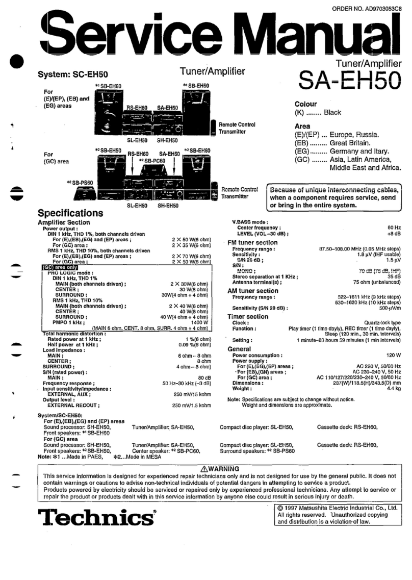
FRANC
ANZEIGE-
FM
(UKW)-MESSENDER
FREQUENZ
DURCH
VOR-
ANSCHLUSS
FREQUENZ
|
¢
insTELLUNG
TERNNUNGS-ABGLEICH
ABGLEICHS-
PUNKTE
ABGLEICHSVERFAHREN
VORBEREITUNG
1.
Den
UKW-Betriebsarten-
.
Wechselst
schalter
in
die
‘‘auto’’-Position
Sense
strony
stellen,
Voltmeter
uber
2.
VR302
auf
minimale
Anzeige
TiefpaGfilter
des
R-Aus
A
2
-Ausgangs
bei
Stereo-
(fe
=
15
~19
kHz)
an
VR302
oaulatorin
L
Ausgangsansch
lisse
(L-Kanalmodulation)
Modus
poeee
des
Gerates
und
auf
minimate,
Anzeige
des
SCIMISPEN,
L-Ausgangs
in
R-Modus
FRANCAIS
gw
CARACTERISTIQUES
(DIN
45
500)
™
SECTION
SYNTONISATEUR
FM
Me
sender
iiber
eine
100,1
MHz
UKW-Kunstantenne
an
|
(400
Hz
den
UKW-Antennenein-}
Modulat.,
gang
anschlieRen,
100%)
(Stereo-Pilotsignal
L oder
R-
10%
moduliert.)
Betriebsart.)
100,1
MHz
Gamme
de
fréquence
87,50~108,00
MHz
Bornes
d’antenne
75Q
(asymétrique)
Sensibilité
S/B
30
dB
1,0
pV
(759)
S/B
26
dB
0,9
pV
(759)
M@
SECTION
SYNTONISATEUR
AM
S/B
20
dB
0,8
pV
(759)
Sensibilité
utilisable
|HF
0,95
pV
(IHF
'58)
Gamme
de
fréquence
Sensibilité
steréo
au
seuil
de
46
dB,
IHF
22
wV/75Q
PO
(MW)
522~1611
kHz
Distorsion
harmonique
totale
GO
(LW)
155~353
kHz
MONO
0,15%
‘
153~351
kHz
(—2
kHz
shift)
STEREO
0,3%
Sensibilité
(S/B
20
dB)
Signal/Bruit
PO
(MW)
a
999
kHz
20
nV,
300
wV/m
MONO
69
dB
(75
GB,
IHF)
GO
(LW)
a
254
kHz
100
pV
STEREO
64
dB
(70
dB,
IHF)
Sélectivité
(+9
kHz)
Réponse
de
fréquence
5
Hz~18
kHz,
+0,5
dB~
—1,5
dB
PO
(MW)
4
999
kHz
55
dB
Sélectivite
alternée
par
canal
GO
(LW)
a
254
kHz
55
dB
normal
+400
kHz
60
dB
Rejection
d’image
Taux
de
capture
1,0
dB
PO
(MW)
a
999
kHz
40
dB
Rejection
d’image
4
98
MHz
55
dB
GO
(LW)
a
254
kHz
40
dB
Rejection
Fl
a
98
MHz
90
dB
Rejection
FI
Rejection
de
réponse
parasite
4
98
MHz
80
dB
PO
(MW)
a
999
kHz
60
dB
Suppression
AM
55
dB
GO
(LW)
a
254
kHz
50
dB
Séparation
steréophonique
1
kHz
.
45
dB
@
DIVERS
10
kHz
30
dB
Fuite
de
porteuse
Tension
de
sortie
0,4
V
19
kHz
~40
dB
(—45
dB,
IHF)
Consommation
ow
38
kHz
—40
dB
(—45
dB,
IHF)
Alimentation
Equilibrage
de
canaux
(250
Hz~6,300
Hz)
+1
dB
Pour
l'Europe
CA
50
Hz/60
Hz,
220V
Point
de
limite
1,0
pV
Dimensions
(LxHxPr)
430
x
53
x
240
mm
Largeur
de
bande
Poids
2,1kg
Amplificateur
Fl
180
kHz
Démodulateur
FM
1000
kHz
MESURAGES
ET
REGLAGES
|
(Sujet
4
changement
sans
avertissement
préalable.)
Nota:
La
bobine
oscillatrice
de
modulation
d’amplitude
(L203)
et
le
transformateur
de
fréquence
intermédiaire
de
modulation
d’amplitude
(T201)
et
le
bobine
ANT
LW
(L251)
ont
déja
été
ajustés
et
ne
nécessitent
pas
de
réglages.
REGLAGE
DE
MA
Réglage
et
équipement
utilisé
.
Voltmétres
électroniques
de
courant
alternatif
et
de
courant
continu
(EVM).
.
Génerateur
de
signaux
MA
(AM-SG).
.
Régler
le
sélecteur
FM-MA
sur
la
position
‘“MW/LW”.
(étape
de
9
kHz).
.
Conserver
la
tension
du
secteur
a
la
tension
nominale.
.
Lasortie
du
signal
du
générateur
ne
doit
pas
étre
plus
élevée
quil
n’est
nécessaire
pour
obtenir
une
tecture
en
sortie.
.
Utiliser
un
tournevis
non-métallique
pour
le
réglage.
FRANCAIS
GENERATEUR
DE
SIGNAUX
MA
FREQUENCE
BRANCHEMENT
|
FREQUENCE
|
D’AFFICHAGE
REGLAGE
DE
RF-MW
(OM)
*Régler
le
commutateur
de
gammes
d‘ondes
sur
la
position
“MW:
:
ELEMENTS
- :
PREPARATIFS
REGLES
PROCEDURE
DE
REGLAGE
612
kHz
1,
Régler
au
maximum
du
(Modulé
4
signal
de
sortie.
612
kHz
L202
.
Régler
le
noyau
en
ferrite
Brancher
le
générateur
30%
par
:
i
nan
$
de
signaux
MA
a
la
borne}
400
Hz)
Voltmétre
(Bobine
d’antenne)
eee
reed
un
de
l’antenne
MA
par
un
électronique
C.A.
ou
condensateur
de
200pF.
oscilloscope
sur
Réale
;
d
Commun
au
chassis.
1503
kHz
bornes
de
sortie
de
:
sionuidesote.
ie
(Entrees
teible)
he
eakied
1503
kHz
"appareil.
CT201
(Trimmer
|
2.
Répéter
les
étapes
(1)
et
(2)
400
fe)
d’antenne)
jusqu’aé
ce
que
la
fréquence
s‘aligne
correctement
avec
\affichage
de
la
fréquence,
155
kHz
‘
ie
ie
ae
du
{module
a
155
kHz
Looe
Fesier
lo
nayvan
anfarhie
Brancher
le
générateur
30%
par
Voltmétre
(Bobine
OSC)
,
de
1259
a
I'side
d'un
de
signaux
MA
ala
borne
400
Hz)
électhaiquee
mou
fournevis:
de
l'antenne
MA
per
un
oscilloscope
sur
condensateur
de
200pF.
bornes
de
sortie
de
.
Régler
au
maximum
du
Commun
oO
chasis.
353
kHz
l'appareil.
signal
de
sortie.
(Entrée
faible)
(modulé
a
353
kH
CT251
.
Répérer
les
étapes
(3)
et
(4)
30%
par
z
(Trimmer
d’antenne)
jusqu’a
ce
que
la
fréquence
400
Hz)
s‘aligne
correctement
avec
\‘affichage
de
la
fréquence.
REGLAGE
DE
FM
Réglage
et
équipement
utilisé
Préparatifs
pour
le
générateur
de
signaux
FM
(FM-SG).
Génerateur
de
signaux
FM
(FM-SG).
.
Almenter
la
sortie
du
générateur
de
signaux
a
la
borne
de
Modulateur
stéréophonique.
l‘antenne
de
|'appareil,
par
l'antenne
fictive
FM
de
75.
Oscilloscope.
,
L'entrée
standard
de
|’appareil
est
de
60
dB
(1
mV),
400
Hz,
Voltmeétres
électroniques
de
courant
alternatif
et
de
courant
100%
de
modulation
[a
cause
de
|’utilisation
de
l‘antenne
continue
(EVM).
fictive,
la
sortie
du
générateur
de
signaux
doit
étre
de
plus
Compteur
de
fréquence
(19
kHz
et
108
MHz
mesurables).
12
dB
(4uV)
(IHF).
Ce
qui
signifie
que
quand
|’entrée
est
de
Filtre
passe-bas
(bobine
de
champ:
15
kHz
~
19
kHz).
60
dB
(1
mV),
la
sortie
du
générateur
de
signaux
doit
étre
de
Régler
le
sélecteur
FM-MA
sur
la
position
“FM”,
72
dB
(4mvV)].
Régler
le
commutateur
de
mode
sur
la
position
‘‘mono”,
BNO
FWN>
*
GENERATEUR
DE
SIGNAUX
FM
. :
oe
; ;
:
Seca
ce
PREPARATIFS
Soerece
PROCEDURE
DE
REGLAGE
BRANCHEMENT
FREQUENCE
REGLAGE
DE
FM-IF
(FREQUENCES
INTERMEDIAIRE)
Branchez
le
générateur
2
A
Brancher
le
voltmeétre
de
signaux
a
la
borne
‘
:
‘
électronique
a
C.C.
Régter
le
noyau
T101
de
telle
7
rah
toca
eoteishety
leds
entre
Bakke
(—)
et
|
7101
(Transfor,
sorte
que
la
tension
mesurée
100.1
MHz
faskleya.
(+)
Atravers
|
de
FI
discri.)
dans
le
mode
de
signal,
soit
de
j
19,
60
a
ti
Pe
in
pons
WOO
Hey:
une
bobine
d’arrét.)
O
mV
dans
Ja
plage
des
300
mV.
d’antenne.)
(Voir
la
Fig.
1)
REGLAGE
DE
V.C.O.
DE
L’
(OSCILLATEUR
COMMANDE
PAR
VARIATION
DE
TENSION)
MULTIPLEX
FM
AVEC
UN
FREQUENCEMETRE
EN
UTILISANT
UN
SYSTEME
ALTERNATIF
.
Signal
mono
de
100,1
MHz,
60
dB
non
modulé
appliqué
a
1.
Appliquer
un
signal
stéréophonique
provenant
du
générateur
Vappareil.
(Fig.
2)
ou
d'une
station
stéréo
au
dispositif
d’accord.
.
Commutateur
de
mode
FM
sur
“‘auto’’.
2.
Ajuster
VR301
jusqu’d
ce
que
|’indicateur
stéréophonique
.
Branchez
le
fréquencemétre
sur
par
lintermédiarie
s‘éclaire,
Cimenter
le
bras
de
VR301,
comme
il
est
montré
a
dune
résistance
(100k).
la
Fig,
3.
Régler
VR301
sur
19
kHz
+
30
Hz.
REGLAGE
DE
LA
SEPARATION
DES
CANAUX
.
Régler
le
commutateur
de
mode
FM
sur
‘‘auto’’,
Raccorder
la
générateur
ifahabieteise
rigs
.
Ajuster
VR302
de
telle
sorte
de
signaux
FM
a
la
100,71
MHz
Rees
que
la
sortie
de
droite
soit
borne
d’antenne
FM
a
(Modulé
a
aus
bores
de
sortie
minimisée
lorsque
le
7
|
travers
l'antenne
fictive
90%
par
de
T'appareil
par
VR302
modulateur
stéréophonique
100,1
MHz
\'intermédiaire
d’‘un
(Séparation)
est
sur
la
gauche
(modulation
du
canal
de
gauche)
et
que
la
sortie
de
gauche
soit
minimisée
sur
la
mode
de
droite.
FM
de
75Q.
(Signal
1
kHz)
fj
x
stéréo
pilote
a
10%
de
(Mode
gauche
aaa
ae
=
modulation.)
ou
droite.)
15
kHz
~
19
kHz}
—4—
840703300
@
YK/IM
5
iy
4
Tele)
&
mw
HOW
TO
PRESET
RADIO
BROADCAST
FREQUENCIES
This
unit
can
be
used
to
preset
as
many
as
16
radio
broadcast
e
Memory
presetting
frequencies:
8
FM
and
8
AM
(MW/LW).
After
broadcast
frequencies
have
been
preset
as
described
below,
any
desired
station
can
be
quickly
and
easily
selected
by
simply
touching
one
button.
Automatic
memory
presetting
Beginning
at
the
frequency
indicated
by
the
digital
display,
the
FM
broadcasting
stations,
MW
broadcasting
stations,
and
LW
broadcasting
stations
will
be
automatically
preset
in
“channels”
1
through
8
for
FM,
1
through
4
forMW,and
5
through
8
for
LW,
respectively,
in
order
upward
from
the
broadcasting
station
of
the
lowest
frequency.
Note
that
in
mountainous
or
remote
areas,
broadcasting
stations
which
have
weak
broadcasting
signals
cannot
be
automatically
preset
into
the
memory
There
are
two
types
of
memory
presetting:
automatic
and
manual.
Select
whichever
is
preferred.
0
Power:
“on”
(
B=
)
y>
Press
the
“FM”,
“MW”
or
“LW”
button.
Set
to
the
minimum
frequency.
eFM:
87.50
MHz
¢
MW:
522
kHz
eLW:
155
kHz
4)
Press.
When
the
frequency
indication
begins
to
change,
release.
5]
Confirm
the
names
(call
signs,
etc.)
of
the
broadcasting
(The
frequency
will
change
stations
which
are
preset
to
each
channel,
and
enter
them
on
upward,
and
the
automatic
the
file
sheet.
presetting
will
begin
with
the
Notes:
broadcasting
station
of
the
1.
In
areas
where
there
are
less
than
8
FM
stations,
the
lowest
frequency
and
will
remaining
channels
(through
channel!
8)
will
be
left
continue
in
order.)
empty.
The
empty
channels
can
be
filled
by
using
manual
memory
presetting.
2.
\If
anew
broadcasting
station
is
preset
into
a
channel,
the
broadcasting
station
which
was
previously
entered
in
that
channel
will
be
automatically
erased.
ys
wey
4-
Tole)
&
Stations
can
be
freely
preset
to
any
desired
channel.
Power:
“on”
(
2+»
)
¥}
Press
the
“FM”,
“MW”
or
“LW”
button.
Press
the
appropriate
tuning
button
to
tune
to
the
desired
broadcast.
e
Auto
tuning
@
Manual
tuning
Press
the
button.
When
the
Press
the
button
momentarily
frequency
indication
begins
and
tune
to
the
desired
station
to
change,
release
the
(the
frequency
will
change
each
button
(a
broadcasting
time
the
button
is
pressed).
station
will
be
selected
automatically).
Repeat
this
operation
until
the
desired
station
is
found.
Memory
indicator
(4)
Press
momentarily,
and
then
release.
(The
memory
indicator
will
illuminate
for
approximately
4
seconds.)
(5)
While
the
memory
indicator
is
illuminated,
press
the
button
of
the
bd
desired
channel.
Ci
When
the
button
is
pressed,
the
memory
indicator
illumination
will
stop,
and
the
presetting
is
complete.
Note:
Note:
If
the
button
is
pressed
continuously,
the
1.
If
the
memory
indication
illumination
frequency
will
begin
to
change,
and
the
stops
before
you
press
the
button,
once
memory
will
be
preset
automatically.
again
repeat
step
(4)
and
then
step
(5).
To
stop
the
automatic
memory
presetting,
2.
If
a
new
broadcasting
station
is
preset
once
again
press
either
the
“up”
button
or
into
a
channel,
the
broadcasting
station
the
“down”
button
which
was
previously
entered
in
that
channel
will
be
automatically
erased.
enter
the
name
(call
sign,
etc.)
of
the
preset
broad-
casting
station
on
the
station
memory
file
sheet.
This
completes
the
procedures
for
presetting
radio
broad-
cast
frequencies.
The
other
preset-tuning
buttons
can
be
preset
in
the
same
way
by
following
steps
(2)
through
(5).
5
ey
4.
Tele)
&
@
DISASSEMBLY
INSTRUCTION
[
Ref.
Me
How
to
remove
the
main
P.C.B.
(1)
Remove
the
4
screws
(@~
@).
(2)
Remove
the
5
screws
(@~
@)
of
front
panel.
(3)
Remove
the
2
rivets
(
@,
@)
and
the
3
screws
(@
~
Q@)
of
main
P.C.B.
OCm
O
Crm
Front
panel
Main
P.C.B.
@
BEFORE
REPAIR
The
power
switch
of
this
unit
is
located
on
the
secondary
side
of
the
power
transformer.
Be
sure
to
disconnect
the
power
cord
from
the
socket
before
servicing.
Also,
do
the
following
before
repair
of
digital
circuits.
(1)
Disconnect
the
power
cord
from
the
socket.
(2)
Using
a
102,
1W
resistor,
short
circuit
electrolytic
“gold”
capacitors
C902
and
C903
momentarily
to
discharge
them.
—-5—
3
ey
£:
Tele)
&
m
MEASUREMENTS
AND
ADJUSTMENTS
Note:
AM
OSC
coil
(L203),
AM
IFT
(T201)
and
LW
antenna
coil
(L251)
have
been
already
adjusted,
and
require
no
adjustment.
AM
ADJUSTMENT
|
Setting
and
Equipment
used
.
AC
and
OC
electronic
voltmeters
(EVM)
5.
Output
of
signal
generator
should
be
no
higher
than
necessary
to
.
AM
signal
generator
(AM-SG).
obtain
an
output
reading.
.
Set
Band
selector
to
‘‘MW/LW”
position.
6.
Use
a
non-metal
screwdriver
for
the
adjustment.
.
Maintain
line
voltage
at
rated
voltage.
AM
SIGNAL
GENERATOR
DISPLAY
i
———
aan
FREQUENCY
PREPARATIONS
PARTS
ADJUSTED
|
ADJUSTING
PROCEDURE
CONNECTION
FREQUENCY
i
S
nat
aes
t
a,
I=
wecuntt
4
5,
23
a
:
Nae
MW-RF
ADJUSTMENT
_ *
Set
band
selector
to
“MW”
position.
612
kHz
Connect
AC
EVM
or
i
:
1.
Adjust
for
maximum
output.
1
(30%
Mod.
612
kHz
scope
to
“OUTPUT”
|
L202
(ANT.
Coil)
|
2.
Adjust
core
of
L202
by
Connect
AM-SG
to
-
with
400
Hz)
screwdriver.
AM
antenna
terminal
a
-
-
a
--
through
200
pF
1.
Adjust
for
maximum
output.
capacitor.
Common
to
1503
kHz
!
Connect
AC
EVM
or
cT201
2.
Repeat
steps
(1)
and
(2)
2]|
chassis.
(Weak
input)
©
(30%
Mod.
©
1503
kHz
scope
to
‘‘OUTPUT”
CANT.
-Teininien
until
the
frequency
correctly
‘
with
400
Hz)
terminals.
:
:
matches
the
frequency
display.
terminals.
LW-RF
ADJUSTMENT
*
Set
band
selector
to
‘'LW"
position.
'
155
kHz
Connect
AC
EVM
or
!
1,
Adjust
for
maximum
output.
3
(30%
Mod
155
kHz
scope
to
“OUTPUT”
L252
(OSC.
Coil)
|
2.
Adjust
core
of
L252
by
Connect
AM-SG
to
with
400
Hz)
|
terminals.
screwdriver.
AM
antenna
terminal
-
pe
mee
eS
ares
=
3
ase
:
ot
through
200
pF
|
|
1.
Adjust
for
maximum
output.
capacitor.
Common
to
353
kHz
:
Connect
AC
EVM
or
CT251
.
2.
Repeat
steps
(3)
and
(4)
4]
chassis.
(Weak
input)
(30%
Mod.
353
kHz
i
scope
to
“OUTPUT”
until
the
frequency
correctly
(ANT.
Trimmer)
with
400
Hz)
|
;
terminals
FM
ADJUSTMENT
*
Setting
and
Equipment
used
Preparation
of
FM
signal
generator
(FM-SG)
FM
signal
generator
(FM-SG).
.
Apply
SG
output
to
antenna
terminal
of
the
set
through
75Q
Stereo
modulator.
FM
dummy
antenna.
Oscilloscope.
.
The
standard
input
of
the
set
is
60
dB
(1
mV),
400
Hz,
100%
AC
and
DC
electronic
voltmeters
(EVM).
modulation
[Because
of
using
dummy
antenna,
SG
output
must
Frequency
counter
(19
kHz
and
108
MHz
measurable).
be
12
dB
(4uV)
plus
(IHF).
That
is,
when
input
60
dB
(1
mV),
Low-pass
filter
(fe
:
15
kHz
~19
kHz).
SG
output
is
to
be
72
dB
(4mvV)].
Set
Band
selector
to
FM”
position
. .
Connect
stereo
modulator
to
FM-SG.
Set
FM
mode
switch
to
““mono”
position.
matches
the
frequency
display.
DNADTRON=
FM
SIGNAL
GENERATOR
DISPLAY
FREQUENCY
PREPARATIONS
PARTS
ADJUSTED
ADJUSTING
PROCEDURE
:
T
CONNECTION
FREQUENCY
FM-IF
ADJUSTMENT
heh
FM-SG
to
|
Connect
DC
EVM
to
Picuch
ISG
ENE
100.1
MHz
between
JGEE
(—)
Adjust
T101
core
so
that
5
2
(90%
Mod.
100.1
MHz
and
(+)
T101
(Discri.
IFT)
voltage
measured
in
signal
dummy
antenna.
: ' : :
with
400
Hz)
through
chock
coil.
mode
is
O
mV
in
300
mV
range.
(Apply
60
dB
(1
mV)
(Refer
to
Fig.
1)
to
antenna
terminal)
a
FM
MPX
V.C.0.
ADJUSTMENT
USING
A
FREQUENCY
COUNTER
USING
ALTERNATE
SYSTEM
.
100.1
MHz,
60
dB
Non-modulated
mono
signa!
applied
to
set.
(Fig.
2)
1.
Apply
stereo
signal
from
generator
or
stereo
station
to
tuner.
6
.
FM
mode
switch
to
‘‘auto”’
position.
2.
Adjust
VR301
until
stereo
indicator
lights
up.
Cement
arm
.
Connect
frequency
counter
to
through
resistor
(100k).
of
VR301
as
shown
in
Fig.
3.
.
Adjust
VR301
to
19
kHz
+
30
Hz.
SEPARATION
ADJUSTMENT
.
Set the
FM
mode
switch
to
Connect
FM-SG
to
“auto”.
FM
antenna
terminal
poe
as
oy
oe
.
Adjust
VR302
so
that
R
through
759
FM
Goce
Mesh
A
i
Had
a
0
output
is
minimized
when
dummy
antenna.
Doe
100.1
MHz
eset
fou
(Separation)
stereo
modulator
is
in
L
(Pilot
10%
Mod.
ee
i:
tie
)
akan
as
19
kHz)
(L
ch.
modulation)
mode
stereo
signal}
ae
i
Ay
and
that
L
pure
is
minimized
in
R
mode.
7