manuals.online logo
Brands
  1. Home
  2. •
  3. Brands
  4. •
  5. Technics
  6. •
  7. Tuner
  8. •
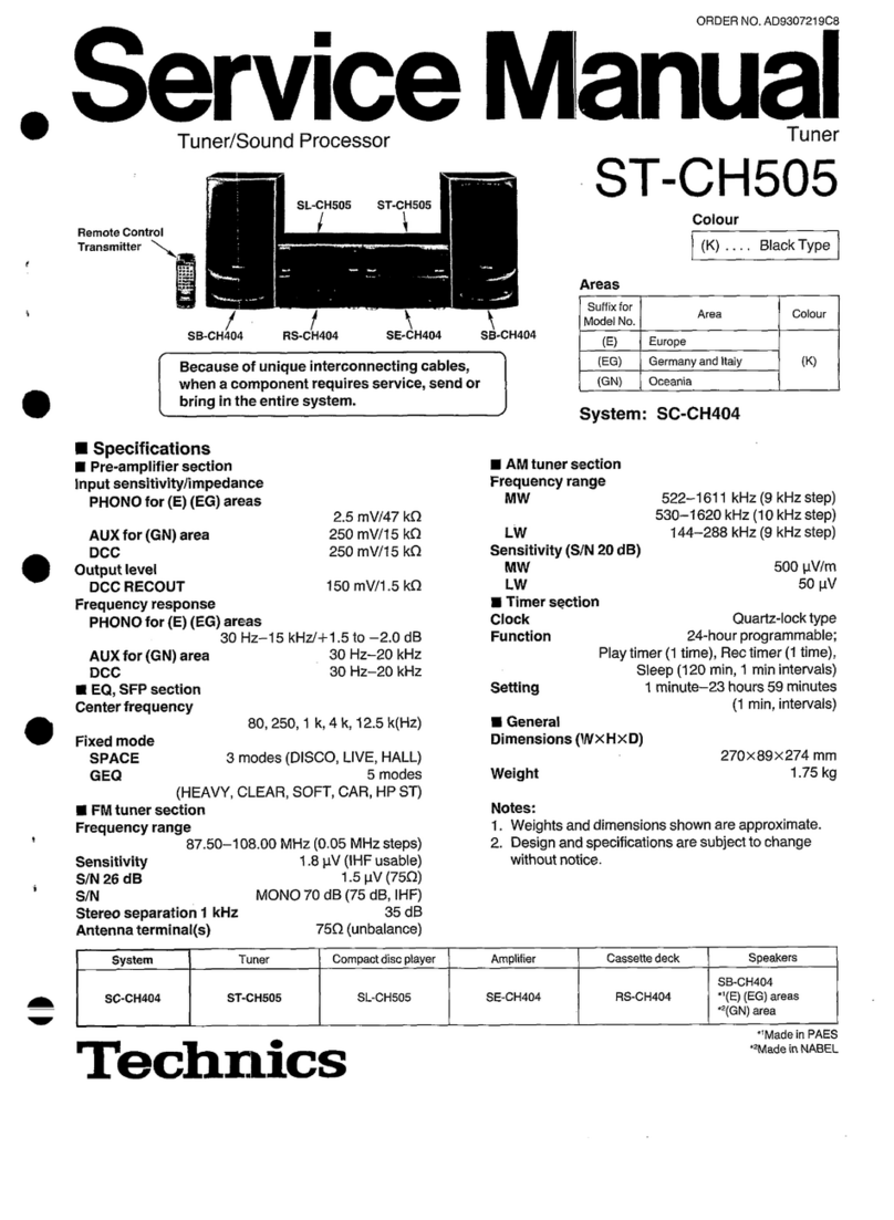
  9. Technics ST-CH505 User manual

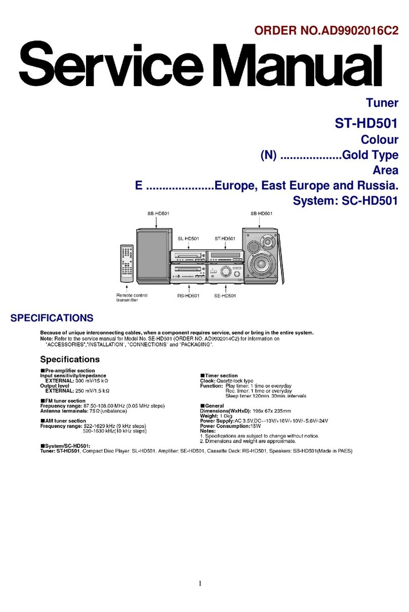
Technics ST-CH505 User manual

Service
Manu
~~
Tuner/Sound
Processor
SL-CH505
Remote
Control
Transmitter,
\
SB-CH404
RS-CH404
SE-CH404
Because
of
unique
interconnecting
cables,
when
a
component
requires
service,
send
or
bring
in
the
entire
system.
M
Specifications
@
Pre-amplifier
section
Input
sensitivity/impedance
PHONO
for
(E)
(EG)
areas
2.5
mV/47
kQ
AUX
for
(GN)
area
250
mV/15
kQ
DCC
250
mV/15
kQ
Output
level
DCC
RECOUT
150
mV/1.5
kQ
Frequency
response
PHONO
for
(E)
(EG)
areas
30
Hz—15
kHz/+1.5
to
-2.0
dB
AUX
for
(GN)
area
30
Hz—20
kHz
DCC
30
Hz—20
kHz
m@
EQ,
SFP
section
Center
frequency
80,
250,
1
k,
4k,
12.5
k(Hz)
Fixed
mode
SPACE
3
modes
(DISCO,
LIVE,
HALL)
GEQ
5
modes
(HEAVY,
CLEAR,
SOFT,
CAR,
HP
ST)
@
FMtuner
section
Frequency
range
87.50—108.00
MHz
(0.05
MHz
steps)
Sensitivity
1.8
pV
(IHF
usable)
S/N
26
dB
1.5
pV
(750)
S/N
MONO
70
dB
(75
dB,
IHF)
Stereo
separation
1
kHz
35
dB
Antenna
terminal(s)
75Q
(unbalance)
SC-CH404
ST-CH505
SL-CH505
‘Technics
ST-CH505
SB-CH404
Compact
disc
player
Amplifier
Cassette
deck
SE-CH404
RS-CH404
ORDER
NO.
AD9307219C8"
al
Tuner
ST-CH505
Colour
(K)
....
Black
Type
Areas
Suffix
for
Model
No.
(E)
(EG)
Germany
and
Italy
System:
SC-CH404
Colour
Europe
@
AM
tuner
section
Frequency
range
522—1611
kHz(9
KHz
step)
530-1620
kHz
(10
KHz
step)
LW
144-288
kHz
(9
KHz
step)
Sensitivity
(S/N
20
dB)
MW
500
pV/m
LW
50
pV
Hi
Timer
section
Clock
Quartz-lock
type
Function
24-hour
programmable;
Play
timer
(1
time),
Rec
tiner
(1
time),
Sleep
(120
min,
1
min
intervals)
Setting
1
minute—23
hours
59
minutes
:
(1
mn,
intervals)
@
General
Dimensions
(WxHxD)
270X8&9
x
274
mm
Weight
1.75
kg
Notes:
1.
Weights
and
dimensions
shown
are
approximate.
2.
Design
and
specifications
are
subject
tochange
without
notice.
SB-CH4i4
“(E)
(EG
areas
“(GN)
asa
*Macie
in
PAES
“Wade
in
NABEL
ST-CH505
m@
Contents
Page
Page
@LOCATION
OF
CONTROLS
.............
00
0eeeee
eee
anaes
2
eWIRING
CONNECTION
DIAGRAM
..............--..-05.
18
@SETTING
THE
TIME
0.000.000
ccc
cc
ccc
eee
e
eect
eee
anes
3
@BLOCK
DIAGRAM.........000
0000.
c
cece
cee
ee
eee
ees
19~21
@DISASSEMBLY
INSTRUCTIONS
.........
atthe
hdc
ohda’
4~6
_
FUNCTION
OF
IC
TERMINALS
.............0.00-.0000
00:
22
ePOWER
SUPPLY
WITH
TUNER
ST-CH505..................
6
@REPLACEMENT
PARTSLIST
............20000-0-00
23~27
@SCHEMATIC
DIAGRAM
2.0.0.0...
ccc
cece
cece
ees
7~14
@CABINET
PARTS
LOCATION
....0.........0000eeceeee
ees
28
@PRINTED
CIRCUIT
BOARD
DIAGRAM.
...............
15~18
NOTE:
Refer
to
the
service
manual
for
Model
No.
SE-CH404
(Order
No.
AD9307218C8)
for
information
on
“ACCESSORIES”,
“STACKING
THE
COMPONENTS”,
“CONNECTIONS”
and
“PACKAGING”.
H
Location
of
Controls
The
functions
indicated
by
the
numbers
with
black
background
(for
example
@)
can
also
be
activated
from
the
remote
control.
R
imer
button
(J
REC
Scord
ner
orven
(Ree
@
Clock/timer
button
(CLOCK/TIMER)
No.
Name
No.
Name
a
External
source
input
select
button
@)
Play
timer
button
(({]
PLAY)
(EXT)
V.bass
button
(V.BASS)
@)
Internal
source
input
select
button
(INT)
-
©)
Voice
mute
button
(KARAOKE)
©
Tuner
source/band
select
button
and
indicator
(TUNER/BAND)
®
EQ/SPACE
mode
ON/FLAT
button
(ON/FLAT)
(4)
Multi-control
buttons
MULTI
CONTROL
@
EQ/SPACE
mode
select
button
(
)
(MODE)
©
©
Remote
control
signal
sensor
(SENSOR)
@
Setting
the
Time
CLOCK/
zZ
ST-CH505
—
3~5
TIMER
O+@)
(Pe
*@)
These
instructions
explain
how
to
set
the
timer
for
16:25
(4:25
p.m.)
on
Wednesday.
Switch
on
the
power
on
the
amplifier.
@
Press
CLOCK/TIMER
to
se-
lect
“CLOCK”.
within
7
seconds:
@
Press
SET.
@
Press
<
or
P
to
select
“WED”.
“416”.
@
Press
SET.
ny
“95”,
MULTI
CONTROL
¢
“Le
setect
SET®
@
Press
SET
to
finish
setting
the
time.
The
display
will
retum
to
the
previous
display
after
about
2
seconds.
When
“E:”
appears
on
the
display:
It
appears
when
you
connect
the
power
supply
cord
for
the
first
time
or
if
there
has
been
a
power
failure.
If
this
happens,
reset
the
time.
If
the
minutes
setting
has
gone
wrong:
1.
Press
CLOCK/TIMER.
2.
Press
SET
3
times.
3.
Press
one
of
SELECT
to
set
the
minute,
and
then
press
SET.
For
your
reference:
To
display
the
clock
again:
Press
CLOCK/TIMER.
The
clock
display
will
appear
for
about
5
seconds.
ST
A
ig
i
st
a
cri
dan
hss
bass
ib
ide
ts
abitar
Diese
sales;
tabbed
ade
centainaess-
ST-CH505
mw
Disassembly
Instructions
“ATTENTION
SERVICER”
Some
chassis
components
may
have
sharp
edges.
Be
careful
when
disassembling
and
servicing.
ee
"Removal
of
the
Cabinet
ee
Removal
of
the
Front
Panel
Ass’y
Procedure
Procedure
152
Cabinet
Front
panel
ass'y
4
1.
Remove
the
5
screws
(Q@~@).
1.
Remove
the
2
screws
(@,
@).
2.
Remove
the
cabinet
in
the
direction
of
arrow.
2.
Remove
the
front
panel
ass’y
in
the
direction
of
arrow.
Procedure
12-3
14
Bottom
board
()
ass'y
Projection
1.
Remove
the
8
screws
(Q@~Q).
2.
Pull
the
rear
panel
in
both
directions
of
arrow
©
to
unlock
it
from
the
projection
of
the
bottom
board
ass’y.
3.
Remove
the
rear
panel
in
the
direction
of
arrow
@.
Ey
Removal
of
the
Connection
(1)
P.C.B.,
Connection
(2)
P.C.B.
and
Tuner
P.C.B.
Connection
(1)
P.C.B.
14-5
=
A
“ia
ZN
Connection
(2)
P.C.B.
e
Remove
the
7
screws
(@)~@).
1.
Release
the
1
claw.
2.
Lift
up
the
tuner
P.C.B.
in
the
direction
of
arrow
@,
and
3.
Remove
the
connection
(1)
P.C.B.
and
connection
(2)
then
remove
the
2
connectors
(CN201A/B,
CN202A/B).
P.C.B.
in
the
direction
of
arrow
@.
ST-CH505
Procedure
—
1-24-56
e
Remove
the
5
screws
(@~@).
nee:
How
to
check
the
Main
P.C.B.
Procedure
13247
Tuner
P.C.B.
Rear
panel
Main
P.C.B.
1.
Remove
the
5
screws
(Q@~@).
4.
Reinstall
the
rear
panel
to
the
main
P.C.B.
and
tuier
2.
Release
the
1
claw.
P.C.B.
and
then
tighten
6
screws
(@~@).
3.
Remove
the
main
P.C.B.
and
tuner
P.C.B.
:
Front
panel
ass'y
Main
PC.
B.
Main
P.C.B.
(Foil
side)
5.
Reinstall
the
front
panel
ass'y
to
the
main
P.C.B.
6.
Check
the
main
P.C.B.
(foil
side)
as
shown
above
ST-CH505
Replacement
of
the
Foot.
1.
Remove
the
4
heat
melted
posts
on
the
bottom
board
ass'y
witha
pair
of
nippers
or
similar
tool.
2.
To
replace
the
foot
(RKA001
1A-2)
on
the
bottom
board
ass'y,
melt
the
4
posts
with
a
soldering
iron.
Ete
5
es
Heat
meited
posts
Foot
Bottom
board
assy
Soldering
iron
Foot
(RKAO011A-2)
@
Power
Supply
with
Tuner
ST-CH505
Power
Supply
to
Main
PCB
1.
Apply
11
V
AC
power
between
C901
and
C902
using
the
service
tool
for
AC
power
supply
as
shown
below.
(The
unit
comes
to
STAND
BY
Mode.)
2.
Short
the
point
[P-sw]to
the
cathode
side
of
diode
D908
as
shown
below.
FL
display
tube
lights
and
the
unit
comes
to
power
ON
mode.
Power
Supply
to
Tuner
PCB
1.
Apply
15
V
DC
power
to
[J912Jand
using
the
service
tool
for
DC
power
supply
as
shown
below.
Note:
When
applying
DC
power,
connect
between
GND
and[CT]using
the
tool.
CNSO!IA
CN8O02A
CNSO3A
(J716)
SHORT
:
POWER
"ON"
(Main
P.C.B.)
DC
POWER
SUPPLY
a
7
ST-CH505
ST-CH505
H
H
7
.
:
AM
(LW/MW)
si
Ii
:
i
@
Schematic
Diagram
eTuner
circuit
(parts
tist
on
pages
23~27)
ee
AE
WW)
aloralline
——)
+
FM
atonal
ine
25>
:
AM
(LW/MW)
OSC
signal
line
ooo
:
FM
OSC
signal
line
Positive
voltage
line
AF
signal
line
1
2
3
4
5 6
7
8
9
10
@\Indicated
voltage
values
are
the
standard
values
for
the
unit
measured
by
the
DC
electronic
circuit
tester
(high-impedance)
with
the
chassis
taken
as
standard.
Therefore,
there
may
exist
some
errors
in
the
voltage
values,
depending
on
the
internal
impedance
of
the
DC
circuit
tester.
No
mark:
FM
mode
(
):
MW
mode
ce
>:
LWmode
EQ
tuner
circuit
For
(£G)
area.
For
(E,GNJareas.
2SC2787FLITA
racoe”--
SSCErSEKTA
A
ee
ace
yw
eoooe
eden
saws
eee
ee
4
Z120
FM
FRONT
END
(RALOOI9)
2SK544F-AC
2SC2786EMKTA
0.47yH
CF201_
|.
28K238
ch
eee
ee
ERY
MFO
Me
he
28C2620
Soar
ae
|
a
|
RF
AMP
rs
22p
FM
MIXER
eC
Of
a
lf
o
43
H
22
FM
MIXER
x
I
--—
i
5.6P
)
8
f
—I—
i
JKION
1
ae
:
mh
z
14
I
}
1
FM
ANT©
>(1)
iT
OSE
L-t-4
(759)
!
H
!
ry
5
z
itr]
.
|
8
(6)
2
a
=
5
5!
SIGN
@—
|
iwss
8
3
\a
83
8
3
|
ae
at
For
(GN)
ie
a
ee
ee
I
areas.
(5)
=
|
FM
ANT
H
|
JKIOI
1
1
r—@
{
|
1
750
1
|
|
|
|
|
|
t
|
|
|
4
28C2996
Qiol
BUFFER
AMP
2sce7a7LTA
ti
(tsi
YY:
LC
--
--
- -
--
—
--
-
-
-
-
-
FM
IF
AMP
es
—
=
Qio2
Pa
Ss
38
2SC2787LTA
AMILW/MW)0SC
38
osT
es
EME
AME,
signal
5
f
Be
feb
oe
191
|
d
a0!
re,
;
ONSHET
25¢
S3IAIRTA
4,
c
clo4
4iv
4
Toi
U
A
2
EXT
aAnT&Y
KioooF,
—_
AIOV
tov
1
ov)
\
POWER
SUPPLY
BUFFER
AMP
[
se
or
CS)
si
aio2
J
(FMOND
v
-
-
25
(ov)
2
For
(E,GN)
5600P---(E,6N)
AM
ANT
5
ow
areas.
(ov)
Q106
©1391
s200P---(€6)
Cc
uKIo1
bee
RIO3
FM
[$B]
LINE
:
14.6¥
lary
O
=
=
¢
|
sol
st
fy
ero
teen)
our
{ore
tea
=
LOOP
ANT
o
=]
RIO3
¢
RI47
RI43
6
o
33
----
(EG)
LAI830-H
AF
SIGNAL
470K
2.2K
D
{
FM/AM
IF
AMP,DET/AM
OSC,MIX/FM
MPX
(ich)
27v
16V10---
(E,GN)
A
x
14.7)
3
cis
{iévioo-teo)
8
§
Th)
3
°
R39
3
=
2.7K
c
od
oy
zo
QI9I-193
rias{
ik
(E,GN)
D
2SC33IIAIRTA
820-~
(EG)
é
LW/MW
SWITCHING
RI48
87
5MH1=——108MHr
470K
RI76
A
390
7
ar
Oz
S
‘9
1K---(E,
GN)
|
aI
ie
RIG6
1
50--
[£6)
|
O:FM
S600P--(E,G
N)
;
:
STEREO
€140
{Be
ooP.
ceo)
ao
al
RECEIVED
SIGNAL:
OV
3.9K-y(E,GN)
;
cNIOl
=
Rug
vie
oT
7
8.2K-~
(EG)
+8(2)
@103,
104
ne
is
ee
Da
a
C4
zecdreatsr™
Tre
FM/AM(LW/MW)
aa
B
(J
ST
EYE
To
BI
coNNECTICN
LOOP
FILTER
|
—}
15}
va
(2)
CIRCUITICNIOS)
Y
aw
c
Ly
sen)
|
(Pace
11)
et
b,
8
C1)
GND
a
14.7
F
1c102
Bug
Bus
Bug
x3
cise
We
Lc7218
a
Pesan)
ae
(ace
(ey
a
a
Mx
pioz
Seats
PLL
FREQUENCY
me
a*
a?
marests
Pot
NTHESIZER
(sj
00
(uw)
SYNTH
ae,
Si
>
aon
|
ae
Len
out
10
connectia,
(3)
ce
(HICIRCUITICNIO2))
[eS
ecnour
|
(Paee
1)
O)
F
H
S22KHr=1611K
Hz
:
ST-CH505
ST-CH505
m@
Schematic
Diagram
eOperation
circuit
(Parts
tist
on
pages
23~27)
1
2 3
4 5
6
7
8
B
OPERATION
CIRCUIT
z6ol
RCOHC~278—E
FL8O!I
(RSLOI60-F)
‘*
(REMOTE
SENSOR)
FL
DISPLAY
7
ODOM
NID
M
DOL
MOD
NEAL
SLDEEDOOUOEDOCECSOECS
PY
A
f
8
ReG7
22k
eereCTSRT
ABCOEFGHIJKLMNOPFGHIu,
297,
sal3
;
INT)
a
te
sol2
ny
i
EXT)
28
B
EDCBA
ABCOEFGHIJKLMNO
:
sail
Sx
(pray)
2y
:
Qa
:
©
UN41IITA
:
baked
Be
LED
DRIVE
d
as
l
HIJ
KLMNOABCDEFGHI
J
KL
MNOP
0807
Oy
28
Oe
For
(E,£G)
areas.
Re72
SPR-3O5MOTF
weass)
2e
a8t2,013
Ro
fg
\~
es
s
5
‘
é e
LED
DRIVE
od
Q8l4
seos
aX
EAEDEDE
NNEOISSISSIE
NG
163545
16216
60K
9\
08
H
i
=
(TUNER
fecae
(KARAOKE)
&
©
SI
GD
OSE
YES
DELP
IOS
3
$¥!
3
/BAND)
i
O)tt—<i—sts
ep
BBL
SRO
TOOESS
=
©
¢
5 O
©
o
o
ey
i
lz
|
a
nm
c
am
Ssev
TT
J
saev
|
ax
[|
a”
F*4.19MHz
ex
M38I73M6245F-
ee
ao
M38I73M6252F
---
GN)
amt
SYSTEM
CONTROL
/
FL
ORIVE
eee
EQ
SPACE)
—
$804
In
MODE)
a-
Nx
sso3_
oN
”
Loft2S1
gs
abe
=o
—.
vy
Sv
sy
©>
rh
ie
0804-806
hata
He
“8
D
seoz
Ox
MAI6STA
(CLOCK/TIMER)&
—
cN8038
5s
a
ee
ES
Moataz
seo1
8o
|_|
—___
Lt
924
MUTE
(TUNER/BAND)
&
©
ae
(3A
MUTE
ds
rt
$4
DATE
IN
|
1,
fy
main
as
O—-B—-O—-O
roa
TA
CIRCUIT
3x
\
5
a
-
4
oe
(CN8O3A)
ay
}
«-
|
{|
lina
nea
39K
.
iceo2
a
6
3
Ha}
ste
(Page
14)
ra
LASGO8M-TE-L
|
z
9)
STEREO
TaGms:
BUS
LINE
DRIVE/
Pano
LT)
so
RESET/HALT
ae
Teese
\Mz.2k
|
83
cNeoz8
,
(\\MiC
DET
ss
mo
VOL.A
E
mono
RECEIVED
(4)
PLOG
sn
:{
om
a
|
uBtaem
KS)
SURR
(CNBO2A)
(r)cuKk2
(Page
14)
(8)
B.0ATA
mameiaees
(9)
B.cLK
ane
Ko)
B.GND
Qsol-81i0
i
UN4INITA
FL
DRIVE
2002
7 F
:
cirbidilas
cNe01B
peo!
fi
SYNC
my
wx
ox
gx
ne
'SS291TA
Cis
rc]
a8
8
8
3
:
EOE
TofS
Main
“2
28
28
es
38
BE
oe
NET
cine
PS
Reae
Ee
2)
oti
ieee
3
(6)
FL2
(Page
14)
F
ee
ome
my
Vy)
Gayl
Go
Wl
Ga
te
ne
9.9V
318
1a802
yose
Q804
42805
Q806
Q807
9808
803
So
38
-24°6V
-246V
-28%6v
ieee)
oe!
8
c
ty)
E
F
G
H
am
ST-CH505
_
$T-CH505
|
—_——ms
:
Positive
voltage
line
:
REC.
OUT
sig
@
Schematic
Diagram
eMain,
Connection
(1)/(2)
circuit
(parts
list
on
pages
23~27)
|
ba
estat
Haat
ce
Sea
:
aia
1
2 3
4
5
6
7
8
9
10
MAIN
CIRCUIT
(PHONO
EQ
AMP/INPUT
SELECTOR/DIGITAL
SOUND
CONTROLLER/BUFFER
AMP/MUTING/REGULATOR
)
For
For
(E,EG)
areas,
CE,
EG)
areas.
R259
R261
180K
i2K
c255
C257
R255
c2si
Res
(e28f|
0.022
6800P
2
al
r
e
zs
O
c209
1aP
28C33I2RTA
<
-
Oo
nm
PHONO
FILTER
AMP
38
[
ay
38
a9|-
:
Qa
we
|
¥en
-0.3¥
Sg
Bo
3am
38%
fn
se
ne
e;
shee
<
lara
3
C379)
AN6558SFE2
FOr
_o.9v
oor
35
83
$8
a3
oo!
Reh
©
PHONO
EQ
AMP
SR
$3
Sg
oe
<3.5Vi3.5visavisavlssvl-3
syli3sy
35v1-3
5y1-35y1L3
if
O—-©—-@)—O
R351
SK
C373
0.22
-3.5V1-34V1-35V
20
Q
vez
B
Len@
S
O—-O-W
o—e
a
85
ay
R256 C252
(ree
(mak
z
3
FT
SF
330
1000P
>
>
Q
1
aux
C256
C258
R264
®y
4+
{9.022
6800P_
68
1c301
e=
R256
crea
R268
caee
M62408FP
RcehO
220
10V33
2.7K
16VIO
ba
a
sue
SOUND
CONTROLLER
R260 R262
(2K
For
(GN)
area,
180K
E
|
°
E
o-|
@x
ceo!
Reo!
55+
BRS
col
1evIO
22K
OST
&N¢
jooP
R393
C377
22K
S0V2.2
‘|
CANCEL
SURROUND
c301
Ic6ol
I6VIO
BA4556F
TI
BUFFER
AMP
c602
R602
16vIO)
22K
REC
OUT
SIGNAL
(L
ch)
a
ee ee
ov
—¢
ee
Lov
J
CO—C9-—
28
CONNECTION(
2
CIRCUIT
NJU7T3ISMT2
INPUT
SELECTOR
E
mG
ee
a
Tee
re
ot
eve
ttt
a
CCNION)
Pp
~—h—
(Pane
8)
30
ty
+02)
pt)
fay
CONNECTION
(1
CIRCUIT
Q601,603
2SJIG4QRTA
SWITCHING
F
to
EN
tuner
ciRcuIT
(CN102)
(Page
8)
ee
he
.
-12-
ST-CH505
ST-CH505
aaa
;
Positive
voltage
line
:
REC.
OUT
signal
line
=
=
mes
;
Negative
voltage
line
WLLL
;
MIC
signal
line
:
:
AF
signal
line
7
8
9
10
11
12 13 14 15
16
17
fan
ee
ee
,
SS
oT
-7.5v.
|
°
i
al
a
Q431,432,441,442
7
2SD2144STA
ac
MUTING
«
ofirEy
:
R447
a
:
Q352
ane
A
Q901
o
Sl2RTA
ot
7
2
28C33I2RTA
2SD2037DE
FTA
os01-
904
R
AMP
68
og
20
ao
c380
igs
ee
g
a
FILTER
AMP
REGULATOR
R901
RLIN4003NO2
YO
2§
m3
m2q
0.01
ae
3
$3
Ta
ARs0
v
08
86
38
og
se
3g
=o.
fr,
,
4wa7
R353
ot
-&
nn
By
Sor
~o
R354
o
a,
i
°
o
o
p
3
ro}
o
-0.9V
82k
88
338
92
ne
3
88
98
62k
;
oN
og
%6
Po
Bo
v8
ON
R437
Precert
3
i
ro
A
»
L
-3.5V1-3.5visavisavissvl3svlasy
3
5V1~3.5¥
-3.4V,
T.4V
as)
ae
-75V
~3.5¥1-34V1-35v
1-3
5v1-34V
1-3.4V
1-35
1-3.5V1~-3.4vL-3.5v)-35¥
SN
Sx
Awe
€
_
if
4
i
—)—-9—O—-0—-O—-9O—-O—0
O—O
(9—(I—)
O—L)—-—-DJ—)
—-D—I—
I)
—I—_D—
So7T
a2
b
23,
cE]
es] ate
Tal
|
al
eee]
[|
te
5
MAIGSTA
eee
BL]
slid)
eli]
Lgl
é
|
Hg
:
c907
0.01
M62408FP
Baio
j
caee
DIGITAL
SOUND
CONTROLLER
47K
6
iM
a
-_———
—
m7
t
Nu
|
7
TP902
of
8x
as
i
R325
a
ayes
3.3K
|
<4
4
|
|
ARo02
2SB1357DEFTA
pore
arene
UEe
|
REGULATOR
POINT
3
eb2l44sTa
393
«C377
C378
«R394
Q401,402
Q405,
433,443
espe
DRIVE
22K
«6
s0v2.2
Sov2.2
22k
2SC3327ABTP
UN4II5TA
<
thy
|
+H
asbeceees
MUTING
MUTING
CONT
§
6-+«
ov
22K
I6VI0
28
|
]
s
zt
Pt
ov
VOICE
CANCEL
SURROUND
bee.
2
©
«
307
Q605,606
Iw33
~35V
UN4IISTA
4
INTERFACE
Q903
-3.5¥
280203
7DEF
TA
63
606
REGULATOR
aT
-35v
S.8V
pom
IS
0907,908
0g
RLIN4O0OSNO2
L
C315
py,
q
1610
a8
a
H
dia
2
=
rey
a2
c3I7
oa
16V10
4a
‘
912
3K
C319
16VI0
HL
a408
2S8D2144STA
Be
j
MUTING
CONT
906
6)—6)—6)
—5)—S)
Q602,604
2SC3940AQSTA
Saat
ev
28J1G4QRTA
RESMEATSN
SHORT
:
POWER
"
O08:
SWITCHING
Q407
TSN
pen
14.7V
E
UN4IIITA
x
Z
|
MUTING
CONT.
an
3
:
=~
QRTA
Rals
os
NG
C387
47P
re
|
oer
Caea
are
MIC
SIGN,
Aosis
MAGOS2MTA
0.6V
Q406
2SD2144STA
MUTING
N47
|
3a
t
RS
ee
etal
e325
1OvI00
-12-
Age
\
R356
6.8K
392
OK
WY
R320
C376
0.012
+
ST-CH505
|
13
14 15 16
74
a
ee
ore
ae
ee
eal
TP903
aE
SY:
Q431,432,441,442
2SD2144STA
MUTING
[
|||
ge
R447
4.7K
R401
IK
A)
t
28D2037DEFTA
REGULATOR
Tay
15Vv
AReol
V/4wa7
4.7K
25V470
:
Acso3
peal=
804
RLINAOOSNO?
C704
18
R22
K
R223
1K
R222
IK
|
eee
Cae
7
wo}
~a
Kio}
sybase
[eey
ey
(7)
R221
1K
19
JK203
coeeereteeemnememe(i§)
LON
cof)
A.
GND
(3)
Reh
eo
(‘REC
Roch
To
SL-CH505
:JKBO1
R410
4.7K
oJ
!
o
=
“151
A
R902
40902
2SBIS57DEFTA
iM
REGULATOR
R302
C302
22K
16VIO
104
-
K
104
c3xoe
2
P
1O000P
+
R606
1.5K
Q401,402
2SC3327ABTP
MUTING
Q405,
433,443
UN4II5TA
MUTING
CONT
D910
MA4120MTA
Q605,606
UN4ILISTA
VAWAT
POWER
SUPPLY
Q904
2SD2144STA
RELAY
DRIVE
0.022
0.022
f
4
C901
c302
POINT
SQ
Ss
L702
iyH
TPI
e)
JK204
hd
Ac!
‘)
RLY/PO
Ls
cr
(4)
SURR/B.DATA
rN
INTERFACE
Q903
2SD2037DEF
TA
VK
REGULATOR
I
I5Vv
Co
.
Kary
cé606.
16VIO.
Ay
me
on
aA
jh
z
<
ly?
We
C921
fokens
—6,8V
OV
c
Avs
MA4O62HTA
DS}
Ansi2”
MAI85TA
7K
MAI85TA.
Apraor
AqQgo0s5
~32v
?
2SB62IAQRSTA
REGULATOR
Abgi7
R921
150
R922
q
°
0
MA4039MTA
4
5.8V-—
71
VOL.
A
(8)
D.GND
re
SE-CH404
:JK201
He
Len our
(5)
+8
a
Reh OUT
CNBOIA
(1)
SYNC
{es
PWwRSW
~5.8V
N
Q408
4
To
EJ
oPERATION
I
Q407
UN4TIITA
MUTING
CONT.
8
:
2SD02144STA
1s)
ff
=
MUTING
CONT
ov
ae
ABSCSO40
AOSTA
aie
CH
TiN
REGULATOR
47K
25V4
atv
x
<Q
25
8.2V
2
30
14.7V
R420
R923
LSK
R93!
Le
ines.
SHORT:
POWER
"ON"
CIRCUIT(CNBOIB)
(Page
10)
Sense
eee
ob
[4]
D.GNDICT)
ta
(s]
vP
Cr)
FL
|
Kay
+813)
9.9V~
It
CNBO2A
R415
R229
1K
IK
(1)
MIC
DET
eae
_2
ai
5
2
er
4l
1K
C402
O00P
c9l4
10V100
wy
wD
Ss
°
+
ADg18
MA4082MTA
MIC
SIGNAL
Q406
2SD2144STA
MUTING
14.7V
RE
{2]
VOL.A
(3]
VoL.8
eres
OS
(51
RLY
To
EROPERATION
CIRCUIT(CNBO2B)
(Page
10)
(10)
B.G
ND
E90!
CNBO3A
(1)
DATA2
(2)
MUTE
(3)
A
MUTE
(4)
DATA
IN
(5]
DATA
to
EJ
operation
CIRCUITICN803B)
Gremomer®
fate
i)
clK
cE
{al
STB
9)
STEREO
(0)
$b
-—13~
~14-
Notes:
@S801
©$802
©S803
@S804
©$808
S809
©S810
eS811
©S812
©S813
@S815
©S816
@S817
©S818
S819
20
ST-CH505
21
22
:
Tuner
source/band
select
switch
(TUNER/BAND)
:
Clock/timer
switch
(CLOCK/TIMER)
:
EQ/SPACE
mode
ON/FLAT
switch
(ON/FLAT)
:
EQ/SPACE
mode
select
switch
(MODE)
Voice
mute
switch
(KARAOKE)
:
V.
bass
switch
(V.BASS)
:
Record
timer
switch
(&!
REC)
:
Play
timer
switch
(@
PLAY)
:
External
source
input
select
switch
(EXT)
:
Internal
source
input
select
switch
(INT)
:
Multi-control
switch
(SET)
:
Multi-control
switch
(A)
:
Multi-control
switch
(¥)
:
Multi-control
switch
(B)
:
Multi-control
switch
(<4)
indicated
voltage
values
are
the
standard
values
for
the
unit
measured
by
the
DC
electronic
circuit
tester
(high-
impedance)
with
the
chassis
taken
as
standard.
Therefore,
there
may
exist
some
errors
in
the
voltage
values,
depending
on
the
internal
impedance
of
the
DC
circuit
tester.
No
mark.
FM
mode
(
mode
<
):
MW
>:
LW
mode
®|mportant
safety
notice:
Components
identified
by
A
mark
have
special
characteristics
important
for
safety.
Furthermore,
special
parts
which
have
purposes
of
fire-
retardant
(resistors),
high-quality
sound
(capacitors),
low-
noise
(resistors),
etc.
are
used.
When
replacing
any
of
components,
be
sure
to
use
only
manufacturer's
specified
parts
shown
in
the
parts
list.
Caution!
IC
and
LSI
are
sensitive
to
static
electricity.
Secondary
trouble
can
be
prevented
by
taking
care
during
repair.
Cover
the
parts
boxes
made
of
plastics
with
aluminum
foil.
Ground
the
soldering
iron.
Put
a
conductive
mat
on
the
work
table.
Do
not
touch
the
legs
of
IC
or
LSI
with
the
fingers
directly.
This
schematic
diagram
may
be
modified
at
time
with
the
development
of
new
technology.
©The
supply
part
number
is
described
alone
in
the
replacement
parts
list.
Ref.
No.
Production
Parts
No.
Supply
Parts
No.
1C6014
BA4558FT1
SVIBA4558F
2801
RCDHC-278-E
RCDHC-278
ST-CH505
ST-CH505
ST-CH505
|
Printed
Circuit
Board
Diagram
(Parts
list
on
pages
23~27)
3
|
4
I
5
2
-_
REP1452C-T---(EG)
»
TUNER
PC.B.|
REPI452D-T--
[E)
chen:
REP1I452E-T-::
(GN)
For(GN)
area.
For(£,EG)areas.
[
[rac awr]
|]
feo
an]
|
AM
ANT
GNDI-(75.2.
(EXT
ANT)
(LOOP
E
m
|
ANT
)
M
My
eM
|
Qe
REP1I663A~M---(E,EG)
@:
MAIN
POR
eee
yey
}
(PLAY
(IN))
DAT/OCC
(REC
(OUT))
For
(GN)area.
[
[exon]
sacl
For
(E,£6)
areas.
SL-CHS505
TP904
|
TP203
&
ay
uke
—
O
O920
re
2
SE-CH404
_—_———
-
4
SHORT:
POWER
"on"
$$
POWER
SUPPLY
POINT
245
=
ST-CH505
ST-CH505
5
6
7
8
9
10
11
12
13 14
FY
rence
ae
i
la
ae
a
Die
Eh
-C.B.{
REPI
-T
REP
1452E-T---
(GN)
(2)
PCB.
(1)
PCB.
For(GN)
areo.
For(E,€G)
areas.
REPIG63A-M--
E,EG)
ce
ty)
|
|
[em
ant]
|
fe
el
REP1I663B-M---(GN)
REP
1663B-M---(GN)
(GNDI=(75.20
(EXT
ANT)
(LOOP
I
a
ANT)
M
My
2)
fl
+
CN201B
ue
CN202B8
<-
CUTN
|
f
Hi
ge
lOBIAC
HOY
1089AB
EW
BO
>—O)
x4
Sp
AN
4
ie
tte
POOSaE
;
i
sta,
i
Terminal
guide
of
IC’s,
transistors
and
diodes
poner
ANGS58SFE2
|
BPin
6381
73M6245F
|
80Pin
.
LAS608M-TE-L
|
14Pin
NG62408FP
100Pin
Ss
wes
[NJU7313MT2
|
30Pin
SZ_
1
fos
——
E
Ze
4
No.l
J,
>
Se
>.
-
KES
<j
[sa8173M6252F
|
80
Pin
2SB621AQRSTA
28C3327ABTP
2SC3940AQSTA
28D2144STA
2SB1357DEFTA
2SD2037DEFTA
|
f
B
£194
A
7
ee
i
Zn
c
8
ce)
c B
c
B
Cc
E
Cc
E
—_{—
MA4039MTA
MA4100MTA
RL1N4003N02
St
ea
MA4051LTA
Ca
MA4120MTA
‘
‘
oy
<
Cathode
MA4051MTA
Cathode
MA4270MTA
a
ee
NS
MA4062HTA
a
a
Cathode
i
a
MA4082LTA
p
MA4082MTA
Anode
Anode
[
Anode
SHORT:
POWER
"ON"
Note:
This
printed
circuit
board
diagram
ma
be
snodified
at
any
time
S16
~
13
14
15 16
CONNECTION
(1)
PCB.
Bee
cesa
eee)
ST-CH505
ST-CH505
>
REPI664A—S-:-(E,EG)
REP1663B-M---(GN)
CN202B
lOBGAC
18
19
20
21
TEN
eu
SFLRS
IG
sistors
and
diodes
ABTP
ee
|
LA1830-H
2SC2785FETA
[ANesseSFe2
|
BPin
M38173M6245F
|
80Pin
meas
SSOaTaL
TA
LAS608M-TE-L_
|
14Pin
M62408FP
100Pin
I3
2SC331
1
AIRTA
28C
A
NJU7313MT2__
|
30Pin
UNGIIETA.
:
UN4111TA
fs
UN4115TA
noi
[M38173M6252F
|
80
Pin
|
2SC3940AQSTA
2SD2144STA
2SB1357DEFTA
2SJ164QRTA
MA165TA
MA185TA
2SD2037DEFTA
1SS291TA
So
se
Cathode
CO
Cathode
A
a
Oo
E
8
Cc
Cc
Ss
8
E
G
Anode
Anode
18)
ITA
TA
'TA
ITA
TA
ITA
SPR-305MDTF
MA4100MTA
RL1N4003N02
MA4120MTA
MA4270MTA
Ca
se
Oe
"
a
Cathode
A
eS
~
Anode
rhs
A
Anode
Ca
J
Note:
This
printed
circuit
board
diagram
may
be
modified
at
any
time
with
the
development
of
new
technology.
-17—-
i
Wiring
Connection
Diagram
(RECiOUT))
peels
z
aux
|--(GN)
[SL—CH505
|
[sE-cH404
|
CONNECTION
(2)
P.C.B.
PTSOI
(Power
transformer)
SOLDER
SIDE
CONNECTION
(1)
PC.B.
CN8028
CN8OIB
Perio
Sg
CNBO3A
er
ts
ee
|
ST-CH505
ST-CH505
@
Block
Diagram
FM
ANTENNA
LAIB30-H
Z120
(FM
FRONT
END)
CF201
CF202
Ic
11
NJUT3I3MT2
FM/AM
IF
AMP,
DET/AM
OSC,MIX/FM
MPX
INPUT
SELECTOR
Q101,102
ce
vamn
“
[Reh]
0107(Q108)
Buffer
omp
[
|
!
|
|
>
For
(GNJ
crea.
to
0605,601
Interface
For
CE,EGJareas.
[
ANG6558SFE2
=o
ee
'
BA4558FTI
J
I
ic601
|
BUFFER
AMP
cH)
ae
p
Peavany
DAT/DCC
L
REC(OUT)
|
SSS
ae
ee
rs
Q103,104
FM/LW/MW
loop
filter
0407,
408
0406
Muting
control
MUTING
ap
acces
a
eS
wees
[Lehiic201,23PIN)
|
I1C201,23PIN)
{an
\9
3
|
|
Be
ees
a
a
O
z
=
3
ie
:
[coir
ereut]
|
re
Six
amp]
2p
y
Ist_]cx
Joata
y
y
|
|
14
16
om
Z
|
g
|
|
=
Yi
|
t
4
=
iy
|
-
°
fe}
7)
MONOY
uy
|
Q
n
we
aw
0
2
4
L
x
x<
>
>
eooavad
J
y
|
ee
OS
a
ee
oh
oe
pee
as
;
1
24
-
‘a
2
F344
75
l
Lc72ie_
Perera
|
:
VOICE
CANCEL
ue
¢8)
SURROUND
:
|
PLL
FREQUENCY
:
I
I
I
SYNTHESIZER
&
|
Ui
eee
ee
ee
ee
i
a
ee
|
eee
(OF
Sl
eS)
ee
|
9
control
3m
circult
L
|
a
a
a
a
a
a
a
oe
ee
IE
[ia
fia
$33
:
/
‘
et
ae
es
as
a
Sa
as
Ba
es
es
eS
;
Q
DATA
IN
a
id
3
2:26
a
LAS608M-TE-L
:
Bek
XS
4
g
Ye
8
|
z
a
a
cP
ae
:
QOATA
Ms
o
=
BUS
LINE
DRIVE
/RESET/HALT
ce
Mss
eueeR
TON
2
184
5
CLK
OUT
M38173M6245F
---.
(E,
EG)
=
16h
JK
2031/2)
96.
CLK
IN
-
48.
DATA
ouT
SYSTEM
CONTROL
/FL
DRIVE
mute
ee
ee
pe.
oara
Joe
44
B.CLK
2)
‘acta
s
wos
ad
'
-
|
M
CHECK
@
suRR
4
—-<4
g
dum ad)
a
a
a
a
he
ee
ey
—
5
Lr
bs
|
a
z
a
ad
o
°
|
|
w
5
2
2
z
2
Fe
a
2
«©
T-LEO
4
|
C4
rs)
°
a
a
=
°
°
re)
awe
|
ss
A
|
casts
nee
ae
te
tee
aie
th
7
°
22
Geis
0807
=
So
> =
So
oe
an
Hy
sl
0
es
P
_——
ee
cee
ee
eee
come
een
eee
exe
ann()
(TUNER/BAND)
e
3
i
|
0C.GNO
.
iS
ort
|
€)
C8
x80oi
>
|
La
|
Oo
Z801
:
oh
(REMOTE
.
|
se
|
er
F
I
a
SENSOR)
o8ol~
B10
DI
may:
FL
drive
$801-804,
808-813,
$815-819
®
Tis
eral
nine
|
j
Ley
oa
tad
ES
|
|
|
Li
a
eh
ee
Sl
9
7
6
I
OISPLAY
~19-
05
ST-CH505
|
.
ST-CH505
Lc72is
NJUT3ISMT2
MIX
/FM
MPX
INPUT
SELECTOR
Notes:
1)
(
)indicates
Pin
No.
of
——
xd)
-
[Ren]
910710108)
ales
7,
[|
DER
-—_
9)
$
right
channel.
1x01
(zy
x2
x
ar
@)
ae
ee
on
1
i
amp
.
ie
For
(GNJ
area.
|
---1-4
bog
ruin
Hh
ee
|
Eee
:
oo
:
AF
SIGNAL
|
vr
dis
_
iis
14
_iis
|
|
|
—>
+
FM
SIGNAL
PLETED
gerne?
U
EREeS
Ue
im
.
“7
|
fy
0605,606
ii
nea
|
mm
AM
(LW/MW)SIGNAL
|
»
EE pg
For
(E,EG}orecs.
_
|
|
|
inertce
|
|
used
tM
OSC
SIGNAL
|
{
ANG6SS8SFE2
|
|
j
>
AM
(LW/MW)
SIGNAL
Me
siier
ave
Tee
Fic251
|
A4SS6FTI
PT
trig
|
\
|
|
|
.
Piccor
|
«
[==>
©
REC
OUT
SIGNAL
|
[re
H
re
HF]
Y
i]
bees
ee
"@®
y
|
amp
:
MIC
SIGNAL
|
Ht:
|
a@
22
ee
1
|
v0
(5)
ppeavun
|
|
Q601
(0602)
DAT/DCC
|
—4+
SWITCHING
I
bo
O]
L
reciour»
O-<
|
I!
!
nie
|
MIC
SW
1
|
(JK
204,10PIN)
9X4
\
MIC
|
0407,
408
—_
(3K204,I2PIN)
ar
a
j
2
Le
sil
a
!
M62408FP
REC
Lch
‘eed
||
(25)
Let
DIGITAL
SOUND
CONTROLLER
anges
ert
7
il
(24)
xs
tl
|
ee
ce ce
ee
ee
ee ee
ee
ee
IN
g—O-
TO
?
-
14
[Ren]
;
apo
Xs
|
cA
cn
|
les
v
é
f
band
Ladd
rf
dd
|
phe
HO
mca
mix
AMP]
SwitcHING
d
(a
STAT
Resistor
iedder
ae
————
>|
12,9,6,3,100,97
(19,22,25,28,34),
11,8,5,2,99,96
(20,23
126,29,32)h
10,7,4,1,98
24,27,3
VOICE
CANCEL
SURROUND
|
(Lk:
VR/VF,EQ
control
circult
uk
204
Ne
eas
a
es
eS
a
Sta
I
cs
el
a
SS
es
ee
as
te
Oe
en
7
(39]
uch
out
3
N
a
-
7
E
Ea
|
0443
0433
|
e408
2
°
Eo
pros
$2!
Muting
fo]
044110442)
[muting
d].0431(0432)
|
muting
d]
040110402)
=
control
'
MUTING
control
|
MUTING
contro!
L
|
MUTING
M38
173M6252F
----
(GN)
td
|
M36173M6245F---
(E,
EG)
0
amuTe
6
A
9}
vor.
SYSTEM
CONTROL
/FL
DRIVE
sia
OR
sf
RO
vee
JOG
8
8S
A
c
2)
SURR/B.
DATA
yoga
bs—————___________________________
ig
D
ie
PWR
SW
CHECK
&
SUS
c
0906,
0918
E
2)
RLY
/PO
-
D
[
Reguiator
|
(15)
+8
E
0904
48)
5)
PT
901
ee
x
OUT
QBit-813
9807
814
(TUNE
M/BAND)
9905,
0916
o91s
Regulator
0903,0991
Regulotor
><]
8]
zsol
(REMOTE
SENSOR)
$801-
8604,
808-813,
$815-6819
Fu
OISPLAY
0901,0905
0901-904
|
Reguiotor
|
Regulator
Q902,0906
FLBO!
@
@
-20-
-21-
ST-CH505
@
Functions
of IC
Terminals
©1C801
(M38173M6245F)
for
(E)
(EG)
areas/(M38173M6252F)
for
(GN)
area
Terminal
Terminal
1
GR
re)
Condensor/resistance
oscillation
terminal
for
fs
|
oro
|
|
Input
for
remote
control
TIMER
an
electronic
failure
detection
ACIN
AC
power
source
input
terminal
for
an
KEY2
i
Operation
(MULT|
CONTROL)
key
signal
electricity
failure/clock
input
/RESET
|
Reset
input
terminal
KEY1
|
Operation
key
signal
input
Power
source
for
pull
up
ISD
i
|
SD
signal
input
for
tuner
Oy.
1
|
(stow
/STEREO
|
STEREO
signal
input
for
tuner
fa]
|
_
—
STB&LATCH|
O
Latch
penal
ootpunte
Mace
IE!)
ane
|
20
|
an
Connected
to
a
seramic
oscillator
jor
system
strobe
signal
output
to
NJU7313
(IC201)
clock
X801
(4.194304
MHz)
31
XOUT
ie)
:
CE
fe)
Chip
enable
signal
output
to
LC7218
(1C
102)
32
Vss
_
Connected
to
GND
CLK
0
Clock
signal
output
to
M62408
(1C301)/
NJU7313
(1C201)/LC7218
(IC
102)
Input
for
MIC
detection
33
MIC
DET
|
,
ay
(Connection:
“L”)
DATA
oO
Data
signal
output
to
M62408
(IC301)/
NJU7313(1IC201)/LC7218
(iC
102)
34
CSi
|
Input
for
chip
selection
DATAIN
{
Data
signal
input
from
LC7218
(IC
102)
|
as
|
CSO
Audio
muting
signal
output
36
/G6
AMUTE
9°
(Volume
of
—10
dB
and
less:
“H”)
t
i
e)
Grid
output
for
FL
display
tube
40
/G10
MUTE
ie)
Main
muting
signal
output
(Normally
“L”)
41
$31
,
13
CLK2
O
|
Serial
clock
output
for
M62408
(IC301)
; ;
Gp
||
Spament
OutpUrter
EE
cisplay
up
56
S16
(Tuner/Amplifier)
DATA2
ie)
Serial
data
output
for
M62408
(IC301)
57
$15
'
B.DATAIN
|
1
|
Data
input
from
bus
;
’
>
|
agent
cutput
for
FE
display
subs
(GEQ)
71
$1
B.CLK
IN
Clock
input
from
bus
72
/G1
e)
Grid
output
for
FL
display
tube
47
|BoATAOUT|
oO
Data
putpet
to
bus
(Normally
“H")
73
Voo
'
5
Vimpression
BUCK-UP
+5
V
impressiot
Clock
output
to
bus
ppg
|
(Normally
“L")
vP
su
—VP
impression
for
FL
dispiay
tubs
POWER
ON
mode:
Output
for
SUR
ON/
D-GNO
—
Connected
to
GND
CHECK
&
OFF
(During
POWER
ON:
“H")
SURR
POWER
OFF
mode:
Demultipter
output
for
76
VREF
=
Standard
voltage
for
A/D
convertor
clock
control
(Connected
to
Vcc)
Power
control
outfut
7
(During
POWER
ON:
“H")
t
Grid
output
for
FL
display
tube
ete
RO
erate
Heat
detection
input
80
(Unusual
situation:
“H")
Audio
muting
2
signal
output
PLOG
fo
|
(Volume
of
—70
dB
and
less:
“H")
Selector
TUNER
output
eee
po
(Output
in
level
“H”)
JOG
B
Rotary
encoder
input
for
main
volume
'
8
t
ST-CH505
™@
Replacement
Parts
List
Notes:
“tmportant
safety
notice:
Components
identified
by
A
mark
have
special
characteristics
important
for
safety.
Furthermore,
special
parts
which
have
purposes
of
fire-retardant
(resistors),
high-quality
sound
(capacitors),
low-noise
(resistors),
etc.
are
used.
When
replacing
any
of
components,
be
sure
to
use
only
manufacturer's
specified
parts
shown
in
the
parts
list.
“The
parenthesized
indications
in
the
Remarks
columns
specify
the
areas.
(Refer
to
the
cover
page
for
area.)
~
Parts
without
these
indications
can
be
used
for
all
areas.
“The
"(SF)"
mark
denotes
the
standard
part.
Ref.
No.
Part
No.
Part
Name
&
Description
|
Remarks
aie
|
[INTEGRATED
CIRCUITS)
|
t
Part
Name
&
Description
|
Remarks
DIODE
~|DIODE
SPR-30SMDTF
[DIODE
{DIODE
[DIODE
DIODE
RLIN4OO3NO2
{DIODE
MA4082LTA
DIODE
|RLIN4OO3NO2
DIODE
MA4120
(DIODE
MAL85TA
‘DIODE
MA4OSI-L
{DIODE
MA4OOMTA
(DIODE
RLIN4003NO2
{DIODE
‘A
D917
MA4039MTA
|
DIODE
‘A
MA4062-H
:DIODE
A
1.
C,
EA/AM
IF
AMP.
/AM
OSC
1.C,
PLL
FREQ.
SYNTHESIZER
NJU7313MT2
|.
C,
INPUT
SELECTOR
;
ANGSSBSFE2
|.
C,
PHONO
£Q
AMP
|(E)
(EG)
1¢30i[Mé24ogrP
|.
C,
DIGITAL
SOUND
CONT.
col
_‘(SVIBA4S58F
(I.
¢,
BUFFER
ANP.
M38173M6245F
|I.
C,
SYSTEM
CONT.
/FL
DRIVE
W381
73M6252F
|T.
C,
SYSTEM
CONT.
/FL
DRIVE
LASGO8M-TE-L
|1.
C,
BUS
LINE/HALT/RESET
C7218
i
(E)
(EG)
((GN)
1
j
{
$y
TRANSISTOR
(S)
2802787L
28C2785FE
UN411FTA
2SC331
IAIRTA
2SC331
LAIRTA
TRANSISTOR
TRANSISTOR
TRANSISTOR
TRANSISTOR
TRANSISTOR
28C3312RTA
|
TRANSISTOR
‘COIL
(S)
UN4115
TRANSISTOR
:
L101
ELESN1ROMA
=
COIL
:
ELEXTR47MAS
COIL
ELEXTIOOKA9
COIL
28D2144S
UN4111
28021448
TRANSISTOR
TRANSISTOR
TRANSISTOR
28021445
TRANSISTOR
UN4115
TRANSISTOR
Q441,
442
=
|28D21445
[TRANSISTOR
UN4115
TRANSISTOR
2SJ164QRTA
|
TRANSISTOR
RLQZB822KT-D
{COIL
"|ELEXTIROKAS
COIL
SLMIBIOM-IM
{COIL
ELESNIROMA
:COIL
ELEXTIROKAS
{COIL
Q605,
606
|
UN4115
_{TRANSISTOR
|FILTER(S)
i
Q801-811
—
|UN4111
TRANSISTOR
RLFFETWNDOIM
[CERAMIC
FILTER
:(E)
(Gi
RLFFETNGDOLL
|CERAMIC
FILTER
i
(EG)
|
{
DISPLAY
'
t
UNALIFTA
28021445
2D2037DEFTA
”128B1357DEFTA
2SD2037DEFTA
TRANSISTOR
TRANSISTOR
TRANSISTOR
TRANSISTOR
TRANSISTOR
Q904
25021448
TRANSISTOR
:FL
DISPLAY
Q905
25B621A-R
|
TRANSISTOR
A
2SC3940AQSTA
|
TRANSISTOR
A
{SWI
TCH(ES)
|
EVQ21405R
_|SR,
TUNER/BAND
EVQ21405R
—
{SW,
CLOCK/TIMER
EVQ21405R
(SW,
ON/FLAT
EVQ21405R
|SW,
MODE
|
|
-23-
DIODE{S)
DIODE
DIODE
D101
MA40S1MTA
D102
MAL65
ST-CH505.
SW,
KARAOKE
SW,
V.
BASS
Part
No.
Part
Name
&
Description
Remarks
$808
SW,
TIMER
REC
i
Ref.
No.
Part
No.
|
Part
Name
&
Description
{
2120
RALOOOG
ITENER
PACK
(FM
FRONT
END)
2120
RALO019
{TUNER
PACK
(FM
FRONT
END)
RLAGZOOSM-T
{COMPONENT
COMBINATION
EVQ21405R
EVQ21405R
SW,
TIMER
PLAY
RCDHC-278-E
REMOTE
SENSOR
SW,
SELECTOR
(EXT)
SW,
SELECTOR
(INT)
—-—_—___—
4
\OSCILLATOR
(S)
SW,
MULTI
CONTROL
(SET)
|
Remarks
(E)
(GN)
EVQ21405R
SW,
MULTI
CONTROL
(UP)
EVQ21405R
EVQ21405R
EVQ21405R
SW,
MULTI
CONTROL
(DOWN)
SW,
MULTI
CONTROL
(RIGHT)
SW,
MULTI
CONTROL
(LEFT)
|RSXZ456KMO7M
|CSCILLATOR
(456KHZ)
RLFDFTDO3M1
(OSCILLATOR
(10.
7MHZ)
[OSCILLATOR
(7.
2MHZ)
RSXA4M1
9503
CONNECTOR
(S)
RIUOGSWO7T
RITOGIWO7T
RJTO63WO7T
RJTOS7WOO7~1
SOCKET
(7P)
CONNECTOR
(7P)
CONNECTOR
(7P)
CONNECTOR
(7P)
RJTOS7WOO7-1
CONNECTOR
(7P)
RJUOOSKOO8M1
RJUOOSKOLOM1
CN201B
RJUOS7¥007
CN202B
RJUOS7#007
CN801B
RJTOO3KOO8-1
RJTOO3KO10-1
E901
SNELO04-1
TRANSFORMER
SOCKET
(8P)
SOCKET
(10P)
SOCKET
(7P)
SOCKET
(7P)
CONNECTOR
(8P)
CONNECTOR
(10P)
EARTH
TERMINAL
4
GND
PLATE
RTP1
146004
RSYOO17M-0
RELAY
POWER
TRANSFORMER
RELAY
JACK
(S)
JK101
RJH4202M
—_‘
[ANTENNA
TERMAINAL
Ti
(0)
JK101
RJH4405-1M
[ANTENNA
TERMAINAL
(GY)
JK201
SJF3068N
[PHONO
(E)
(EG)
/AUX
(GN)
JK202
SJF3069-5N
|DAT/DCC
JK203
RJTOSSKIS
CONNECTOR
(15P)
(BLACK
TYPE)
an
Tne
JK204
RJTOBSWIS
—_[CONNECTOR(15P)
(WHITE.
TYPE)
=
4
COMPONENT
COMBINATION
(S)
RL122006M-T
COMPONENT
COMBINATION
oa

Other manuals for ST-CH505

1

Other Technics Tuner manuals

Technics ST-9038 User manual

Technics

Technics ST-9038 User manual

Technics ST-HD505 User manual

Technics

Technics ST-HD505 User manual

Technics ST-HD50 User manual

Technics

Technics ST-HD50 User manual

Technics ST-GT350 User manual

Technics

Technics ST-GT350 User manual

Technics ST-CO1 User manual

Technics

Technics ST-CO1 User manual

Technics ST-HD55 User manual

Technics

Technics ST-HD55 User manual

Technics ST-G570 User manual

Technics

Technics ST-G570 User manual

Technics ST-8044 User manual

Technics

Technics ST-8044 User manual

Technics ST-9600 User manual

Technics

Technics ST-9600 User manual

Technics ST-HD505 User manual

Technics

Technics ST-HD505 User manual

Technics SA-DV290EE User manual

Technics

Technics SA-DV290EE User manual

Technics ST-X302L User manual

Technics

Technics ST-X302L User manual

Technics ST-X301L User manual

Technics

Technics ST-X301L User manual

Technics ST-610L Building instructions

Technics

Technics ST-610L Building instructions

Technics ST-S2L User manual

Technics

Technics ST-S2L User manual
Technics ST-8055 User manual

Technics

Technics ST-8055 User manual

Technics ST-G90 User manual

Technics

Technics ST-G90 User manual

Technics ST-CH570 User manual

Technics

Technics ST-CH570 User manual

Technics SA-EH50 User manual

Technics

Technics SA-EH50 User manual

Technics SA-EH750 User manual

Technics

Technics SA-EH750 User manual

Technics ST-7300 User manual

Technics

Technics ST-7300 User manual

Technics Quartz ST-G7 User manual

Technics

Technics Quartz ST-G7 User manual

Technics ST-GT550 User manual

Technics

Technics ST-GT550 User manual

Technics Quartz ST-G7 User manual

Technics

Technics Quartz ST-G7 User manual

Popular Tuner manuals by other brands

NAD C 426 owner's manual

NAD

NAD C 426 owner's manual

HDHomeRun 20121008 installation instructions

HDHomeRun

HDHomeRun 20121008 installation instructions

Harley Benton MT-100 manual

Harley Benton

Harley Benton MT-100 manual

Philips 22AV1150 manual

Philips

Philips 22AV1150 manual

Fzone Music Technology Co., Ltd FT-002C user manual

Fzone Music Technology Co., Ltd

Fzone Music Technology Co., Ltd FT-002C user manual

ADS Technologies USBAV-709-EF Hardware and software manual

ADS Technologies

ADS Technologies USBAV-709-EF Hardware and software manual

AUDAC TMP40 user manual

AUDAC

AUDAC TMP40 user manual

Grace Digital TUNER PRO GDI-IRTP800 user guide

Grace Digital

Grace Digital TUNER PRO GDI-IRTP800 user guide

Ortega SEA DEVIL user manual

Ortega

Ortega SEA DEVIL user manual

ADS Technologies USBAV-701 user guide

ADS Technologies

ADS Technologies USBAV-701 user guide

Crestron ATC-AMFMXM Operations & installation guide

Crestron

Crestron ATC-AMFMXM Operations & installation guide

Toa IR-802T operating instructions

Toa

Toa IR-802T operating instructions

SEA 1612C Instruction and maintenance manual

SEA

SEA 1612C Instruction and maintenance manual

Sony ST-S770ES operating instructions

Sony

Sony ST-S770ES operating instructions

One Remote iRadio 2 user manual

One Remote

One Remote iRadio 2 user manual

Ten-Tec 238c Installation

Ten-Tec

Ten-Tec 238c Installation

McIntosh MR85 owner's manual

McIntosh

McIntosh MR85 owner's manual

Sony ST-EX880 Service manual

Sony

Sony ST-EX880 Service manual

manuals.online logo
manuals.online logoBrands
  • About & Mission
  • Contact us
  • Privacy Policy
  • Terms and Conditions

Copyright 2025 Manuals.Online. All Rights Reserved.