manuals.online logo
Brands
  1. Home
  2. •
  3. Brands
  4. •
  5. Technics
  6. •
  7. Tuner
  8. •
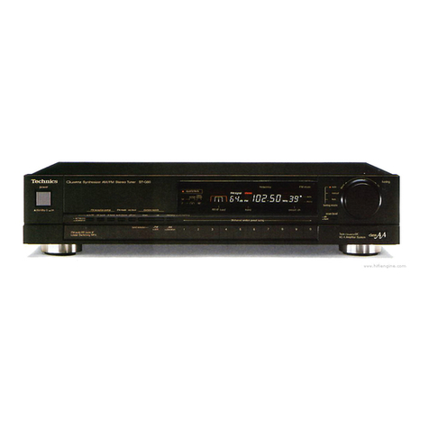
  9. Technics ST-G560L User manual

Technics ST-G560L User manual

Other Technics Tuner manuals

Technics ST-G90 User manual

Technics

Technics ST-G90 User manual

Technics ST-GT550 User manual

Technics

Technics ST-GT550 User manual

Technics SA-EH50 User manual

Technics

Technics SA-EH50 User manual

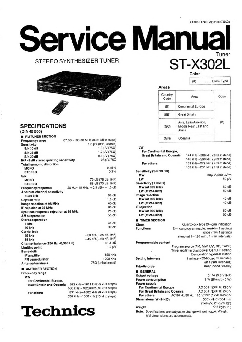
Technics ST-X302L User manual

Technics

Technics ST-X302L User manual

Technics ST-300 User manual

Technics

Technics ST-300 User manual

Technics ST-GT630 User manual

Technics

Technics ST-GT630 User manual

Technics QUARTZ ST-X999L User manual

Technics

Technics QUARTZ ST-X999L User manual

Technics ST-7300 User manual

Technics

Technics ST-7300 User manual

Technics QUARTZ ST-Z400L User manual

Technics

Technics QUARTZ ST-Z400L User manual

Technics ST-9038 User manual

Technics

Technics ST-9038 User manual

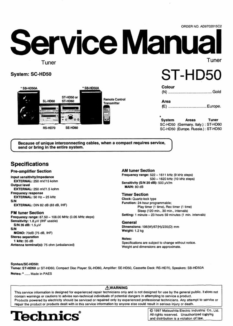
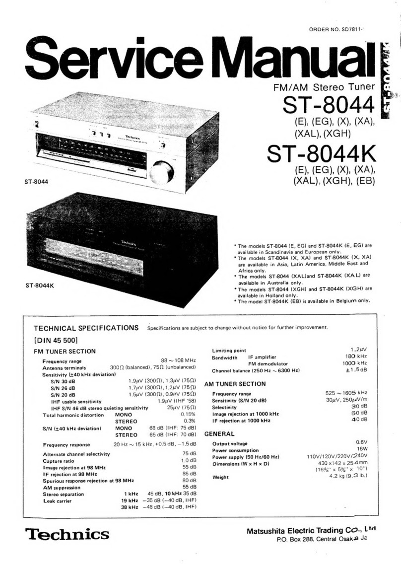
Technics ST-8044 User manual

Technics

Technics ST-8044 User manual

Technics ST-500 User manual

Technics

Technics ST-500 User manual

Technics ST-CH505 User manual

Technics

Technics ST-CH505 User manual

Technics ST-S2L User manual

Technics

Technics ST-S2L User manual

Technics Quartz ST-G45AL User manual

Technics

Technics Quartz ST-G45AL User manual

Technics QUARTZ ST-G460L User manual

Technics

Technics QUARTZ ST-G460L User manual

Technics ST-610L Building instructions

Technics

Technics ST-610L Building instructions

Technics Quartz ST-G45A User manual

Technics

Technics Quartz ST-G45A User manual

Technics ST-HD515 User manual

Technics

Technics ST-HD515 User manual

Technics ST-9600 User manual

Technics

Technics ST-9600 User manual

Technics QUARTZ ST-X999 User manual

Technics

Technics QUARTZ ST-X999 User manual

Technics ST-CA01 User manual

Technics

Technics ST-CA01 User manual

Technics Quartz ST-G7 User manual

Technics

Technics Quartz ST-G7 User manual

Technics ST-7600 User manual

Technics

Technics ST-7600 User manual

Popular Tuner manuals by other brands

Arcam DT91 Handbook

Arcam

Arcam DT91 Handbook

HDHomeRun 20121008 installation instructions

HDHomeRun

HDHomeRun 20121008 installation instructions

Eico HFT-92 instruction manual

Eico

Eico HFT-92 instruction manual

MFJ MFJ-928 instruction manual

MFJ

MFJ MFJ-928 instruction manual

Teac T-1D Service manual

Teac

Teac T-1D Service manual

NAD C 445 owner's manual

NAD

NAD C 445 owner's manual

Sony ST-SA5ES operating instructions

Sony

Sony ST-SA5ES operating instructions

Pioneer GEX-P700DAB Operation manual

Pioneer

Pioneer GEX-P700DAB Operation manual

Sirius Satellite Radio SC-FM1 user guide

Sirius Satellite Radio

Sirius Satellite Radio SC-FM1 user guide

Antique Automobile Radio 283501B Installation and operating instructions

Antique Automobile Radio

Antique Automobile Radio 283501B Installation and operating instructions

Sanyo FMT M15L Service manual

Sanyo

Sanyo FMT M15L Service manual

Monacor PA-1200R instruction manual

Monacor

Monacor PA-1200R instruction manual

Manhattan 176156 user manual

Manhattan

Manhattan 176156 user manual

Marantz ST-15S1 user guide

Marantz

Marantz ST-15S1 user guide

Korg HA-40 owner's manual

Korg

Korg HA-40 owner's manual

Pioneer XC-IS21T Service manual

Pioneer

Pioneer XC-IS21T Service manual

Harman Kardon TU915 Technical manual

Harman Kardon

Harman Kardon TU915 Technical manual

Tunersys WS16 1 quick start guide

Tunersys

Tunersys WS16 1 quick start guide

manuals.online logo
manuals.online logoBrands
  • About & Mission
  • Contact us
  • Privacy Policy
  • Terms and Conditions

Copyright 2025 Manuals.Online. All Rights Reserved.

ORDER
NO.
AD8905130C8
Service
Manual
CYUARTZ
Synthesizer
LW/MW/FM
Stereo
Tuner
SPECIFICATIONS
(DIN
45
500)
Mi
FM
TUNER
SECTION
Frequency
range
87.50
~
108.00
MHz
87.525~
108.00
MHz
(+25
kHz
shift)
Sensitivity
1.5
uV
(IHF,
usable)
SIN
30
dB
1.3
pV
(75
O)
SIN
26
dB
1.2
uV
(75
Q)
SIN
20
dB
0.9
pV
(75
Q)
IHF
46
dB
stereo
quieting
sensitivity
28
wV/75
QD
Total
harmonic
distortion
MONO
(normal)
0.015
%
STEREO
(normal)
0.02
%
S/N
MONO
72
dB
(80
dB,
IHF)
STEREO
66
dB
(73
dB,
IHF)
Frequency
response
4Hz~15
kHz,
+0.5
dB~
—1.0
dB
Alternate
channel
selectivity
normal
+
400
kHz
50
dB
super
narrow
+200
kHz
25
dB
Capture
ratio
1.0
dB
Image
rejection
at
98
MHz
100
dB
IF
rejection
at
98
MHz
100
dB
Spurious
response
rejection
at
98
MHz
110
dB
AM
suppression
55
dB
Stereo
separation
1
kHz
60
dB
10
kHz
45
dB
Carrier
leak
19
kHz
~55
dB
(—60
dB,
IHF)
38
kHz
—40
dB
(—45
GB,
IHF)
Channel
balance
(250
Hz~
6,300
Hz)
+1.0
dB
Limiting
point
0.85
pV
Bandwidth
IF
amplifier
180
kHz
FM
demodulator
1000
kHz
Antenna
terminals
75
Q
(unbalanced)
Technics
Tuner
Color
(K)...Black
Type
(S)...Silver
Type
Area
Country
Code
|
Area
Color
(E),
(E5)
|
Continental
Europe
{K)
(S)
(EB)
Great
Britain
(K)
(S)
(EF)
France
(K)
WAM
TUNER
SECTION
Frequency
range
MW
522
kHz~
1611
kHz
(9-kHz
steps)
530
kHz
~
1620
kHz
(10-kHz
steps)
LW
155
kHz
~
353
kHz
(9-kHz
steps)
153
kHz~
351
kHz
{—2-kHz
shift)
Sensitivity
(S/N
20
dB)
MW
20
pV,
300
uVv/m
LW
50
uv
Selectivity
(+9
kHz)
MW
(at
999
kHz)
50
dB
LW
(at
254
kHz)
50
dB
Image
rejection
MW
(at
999
kHz)
40
dB
LW
(at
254
kHz)
40
dB
IF
rejection
MW
(at
999
kHz)
60
dB
LW
(at
254
kHz)
35
dB
@
GENERAL
Output
voltage
0.3
V
(0.6V
IHF)
Power
consumption
9W
Power
supply
AC
50
Hz/60
Hz,
240V
Dimensions
(W
x
H
x
D)
430
x
69
x
298
mm
(16-15/16"
x
2-23/32”
x
11-23/32”)
Weight
2.7
kg
(6
Ib.)
Note:
Specifications
are
subject
to
change
without
notice.
Weight
and
dimensions
are
approximate.
Matsushita
Electric
Industrial
Co.,
Ltd.
Central
P.O.
Box
288,
Osaka
530-91,
Japan
m@
CONTENTS
Page
Page
ACCESSORIES
co
es
hth
wad
oOo
cys
Rhee
deans
2
CIRCUIT
BOARDS
AND
WIRING
CONNECTION
CONNECTIONS
.........
0c
ccc
ee
teen
cence
net
eee
e
eee
2
DIAGRAM
3.536
esi
seas
Lette.
haGued
Seda
eens
15,16
LOCATION
OF
CONTROLS
.............-.
0c
e
eens
3
FUNCTIONS
OF
IC
TERMINALS..................05.
17
DISASSEMBLY
INSTRUCTIONS.
..............004.
4,5
DESCRIPTION
OF
FLPANEL
..................005-
18
MEASUREMENTS
AND
ADJUSTMENTS
............
6~8
TERMINAL
GUIDE
OF
IC’S,
TRANSISTORS
AND
BLOCK
DIAGRAM
.........
0.
cece
eee
eee
tee
eee
9,10
DIODES
|
Acse-3403
ead
oS
A
ERS
et
os
18
SCHEMATIC
DIAGRAM
...........-.
cece
ee
eee
11~14
RESISTORS
AND
CAPACITORS
..............
19~21
REPLACEMENT
PARTS
LIST
.............
00008
19~23
EXPLODED
VIEW
.......
ccc
ccc
ccc
eects
24
m@
ACCESSORIES
Stereo
connection
cable
(SUP2276)
...............0-5
1
e@Screws
(XTB3+10AFZ)
.......
cece
cece
eee
ee
eens
2
@FM
indoor
antenna
(SSA270M)
.................
ee
eee
1
eAttachment
plug
(SUP9009
for
[EB]
area
only)..........
1
@AM
loop
antenna
(SPB1162T)
...........
0. ee
eee
eee
1
@AC
power
supply
Cord
........
0...
cece
ce
eee
ees
1
e@AM
antenna
holders
(SMA233-1M)
.............00005
1
For
[EB]
area
only
(SJA193)
(SMA231M)
.........0--
eee
eee
1
For
others
areas
(SFDACO5E03)
m@
CONNECTIONS
This
unit
WO
bee
(R)
()
Household
AC
outlet
Stereo
connection
AC
power
supply
cord
Fit
a
suitable
plug
to
an
AC
power
cable
(included)
(included)
supply
cord.
(ARYL)
Amplifier
(not
included)
Please
file
and
use
this
supplement
manual
together
with
the
Service
Manual
for
Model
No.
ST-G560,
Order
No.
AD8906196C2
(EG,
Ei
areas),
or
ST-G560L,
Order
No.
AD8905130C8
(E,
E5,
EB,
EF
areas).
ORDER
NO.
AD8911350S2
Service
Manual
Tuner
©
T-G560
ST-G560L
Area
Country
Code
Color
(K)...Black
Type
(S)...Silver
Type
Area
Color
F.R.
Germany
Note:
;
(Ei)
Italy
(K) (S)
®The
purpose
of
this
supplement
is
to
correct
errors
in
the
“Replacement
Parts
List”.
——
a
:
(E),
(E5);
Continental
Europe
(K)
(S)
Please
correct
your
service
manual
as
follows.
ABI:
AEme
|
Omen
ten
GUrOpe
i}
SISK
2
(EB)
Great
Britain
(K) (S)
(EF)
France
(K)
ST-G560
(Page
21
of
service
manual.)
Ref.
No.
|
aa,
ehenge
ol
Panhe.
Part
Name
&
Description
Remarks
Original
New
CABINET
AND
CHASSIS
RFKNTGS560E-K
RGKO090A-K
GRILL
(Black
Type)
RGKO0090A-S
RFKNTGS560E-S
GRILL
(Silver
Type)
RFKGTG560EGK
RFKGTG560EGS
RYP0123-K
RYP0124-S
23
23
ST-G560L
(Page
23
of
service
manual.)
Ch
f
Part
No.
Ref.
No.
ee
ange
Part
Name
&
Description
Original
New
FRONT
GRILL
(Black
Type)
FRONT
GRILL
(Silver
Type)
CABINET
AND
CHASSIS
16
RGKOO90A-K
RFKNTGS60E-K
RGKOO90A-S
RFKNTGS5S60E-S
FRONT
PANEL
(Black
Type)
FRONT
PANEL
(Silver
Type)
|
Remarks
|
16
23
RYP0097-K
RFKGTG560LEK
23
RYP0098-S
RFKGTGS560LES
Technics
FRONT
PANEL
(Black
Type)
FRONT
PANEL
(Silver
Type)
Matsushita
Electric
Industrial
Co.,
Ltd.
Central
P.O.
Box
288,
Osaka
530-91,
Japan
Printed
in
Japan
F891107900TW
ORDER
NO.
AD8905130C8-A
vim
ST-G560L
Mi
MESSUNGEN
UND
EINSTELL
METHODEN
@
LW/MW/FM
Einstellungen
der
Bedienelemente
und
zu
verwendende
Gerate.
¢
MW
und
UKW
MeBsender
(MW
und
UKW
Nebsender)
¢
Keramischer
Kondensator
(200
pF)
¢
Stereo-Modulator
*
Oszilloskop
©
Verzerrungs-Analystator
¢
Frequenzzahler
©
Elektronische
Wechselstrom-und
¢
Drosselspule
(100yH)
Gleichstrom-Voltmeter
(EVM)
e
Widerstand
(100
KQ)
Anmerkung:
Fur
Z202,
L303
und
L304,
werdeven
justiert
Ersatzteil
geliefert.
Dien Kern
dieses
Teils
daher
nicht
drehen.
MW-HF-JUSTIERUNG
.
Der
Testaufbau
ist
in
der
Abbildung
gezeigt.
Anmerkung:
Stellen
Sie
die
Einheit
auf
“MW”
Betrieb.
Der
Antenneneingang-Signalpegel
muB
so
niedrig
wie
.
Radio
und
Signalgenerator
auf
612kHz
einstellen.
méglich
und
frei
von
automatischer
.
Radio
und
Signalgenerator
auf
1503kHz
einstellen.
werstarkungsregelung
(AGC)
sein.
.
2201
(MW-Antennenspule)
auf
maximale
Ausgangsleistung
abgleichen.
.
Die
Schritte
3~5
wiederholen.
LW-HF-JUSTIERUNG
.
Der
Testaufbau
ist
in
der
Abbildung
gezeigt.
6.
Die
Schritte
3~5
wiederholen.
.
Stellen
Sie
die
Einheit
auf
“LW”
Betrieb.
.
Die
Radiofrequenzanzeige
und den
Messender
auf
155kHz
einstellen.
.
Die
Radiofrequenzanzeige
und den
Messender
auf
353
kHz
einstellen.
.
2201
(LW-Antennenspule)
auf
maximale
Ausgangsleistung
abgleichen.
Anmerkung:
Der
Antenneneingang-Signalpegel
muB
so
niedrig
wie
mdglich
und
frei
von
automatischer
werstarkungsregelung
(AGC)
sein.
UKW-MONO-VERZERRUNGS-JUSTIERUNG
.
Der
Testaufbau
ist
in
der
Abbildung
gezeigt.
.
Schritte
4
und
5
einige
Male
wiederholen.
.
Stellen
Sie
die
Einheit
auf
‘‘FM
(UKW)”
Betrieb.
.
Versichern
Sie
sich,
daB
die
Verzerrungsfaktoren
von
.
Die
Radiofrequenzanzeige
und den
Messender
auf
Kanal
L
und
Kanal
R
ann&hernd
gleich
sind
und
auf
ein
100.10
MHz
einstellen.
Minimum
gehalten
sind.
.
Den
Kern
von
T101
so
justieren,
daB
die
im
Signalzustand
gemessene
Spannung
OmV
(0+
20
mV)
im
300
mV-Bereich
betragt.
-
7102
so
justieren,
daB
der
Verzerrungsfaktor
des
linken
Kanals
minimal
wird.
TRENNUNGS-JUSTIERUNG
1.
Der
Testaufbau
ist
in
der
Abbildung
gezeigt.
.
VR301
so
justieren,
daB
der
R-Ausgang
minimal
ist,
wenn
2.
Stellen
Sie die
Einheit
auf
“FM
und
IF
normal”
Betrieb.
der
Stereomodulator
im
L-Betriebszustand
(Linker
Kanal
3.
Die
Radiofrequenzanzeige
und den
Messender
auf
moduliert)
ist.
100.10
MHz
einstellen.
Anmerkung:
Fir
die
Justierung
ist
ein
Schraubendreher
aus
Kunststoff
zu
verwenden.
UKW-SIGNALSTARKEPEGELS-JUSTIERUNG
.
Durch
Dricken
der
UKW-Signaltaste
das
1.
FOr
den
AnschluB
des
Priifgerates
siehe
die
Abbildung.
Flissigkristalldisplay
von
“frequency”
auf
“dB”
2.
Das
Gerat
auf
“FM
und
IF
normal”
stellen.
umschalten.
3.
Das
Hochfrequenz-Anzeigegerat
und
den
.
VR101
so
einstellen,
da®
54dB
angezeigt
wird.
Signalgenerator
auf
100.10
MHz
stellen.
“54dB”
wird
auf
dem
Fldssigkristalldisplay
angezeigt.
.
Die
Schritte
4,5
wiederholen:
FRANCAIS
Mi
MEAURAGES
ET
REGLAGES
mm
LW/MWIM-F.
Positionnements
des
commandes
et
équipement
utilisé
¢
Générateur
de
signaux
AM
et
FM
(AM
et
FM-
SG)
¢
Modulateur
stéréophonique
e
Analyseur
de
distorsion
¢
Oscilloscope
¢
Compteur
de
fréquence
¢
Bobine
d’amortissement
d’arrét
(100H)
e
Résistance
(100
kQ)
¢
Condensateur
céramique
(200
pF)
¢
Voltmétre
électronique
a
C.A.
et
C.C.
(EVM).
Nota:
Pour
Z202,
L303
et
L304,
des
éléments
réglés
sont
fournis.
Aussi,
ne
pas
tourner
les
noyaux
de
ces
piéces.
REGLAGE
DE
A.M.-H.F.
.
Le
raccordement
de
l’équipement
d’essai
est
montré
sur
Villustration.
.
Régler
l'appareil
sur
le
mode
“MW”.
.
Régler
le
cadran
radio
et
le
générateur
de
signaux
sur
612kHz.
.
Régler
le
cadran
radio
et
le
générateur
de
signaux
sur.
1503
kHz.
.
Régler
2201
(bobine
ANT
A.M.)
pour
une
sortie
maximale.
REGLAGE
DE
RE-LW
1.
Le
raccordement
de
l’équipement
d’essai
est
montré
sur
Villustration.
.
Régler
l'appareil
sur
le
mode
“LW”.
.
Régler
le
réglage
de
|’affichage
de
radiofréquence
et
du
générateur
de
signaux
sur
612kHz.
.
Ajuster
le
réglage
de
l’affichage
de
radiofréquence
et
du
générateur
de
signaux
sur
353kHz.
.
Régler
Z201
(bobine
ANT
LW)
pour
une
sortie
maximale.
REGLAGE
DE
DISTORSION
MONOPHONIQUE
M.F.
1.
Le
raccordement
de
l’équipement
d’essai
est
montré
sur
illustration.
2.
Régler
l'appareil
sur
le
mode
“FM”.
3.
Régler
le
réglage
de
l’affichage
de
radiofréquence
et
du
générateur
de
signaux
sur
100.10
MHz.
.
Ajuster
le
noyau
de
T101
de
telle
sorte
que
la
tension
mesurée
sur
le
mode
de
signaux
soit
de
OmV
(0+
20
mV)
dans
une
plage
de
300mvV.
REGLAGE
DE
SEPARATION
.
Le
raccordement
de
I'équipement
d’essai
est
montré
sur
Villustration.
.
Régler
l’appareil
sur
le
mode
“FM
et
IF
normal”.
.
Ajuster
le
réglage
de
l’affichage
de
radioféquence
et
du
générateur
de
signaux
sur
100.10
MHz.
REGLAGE
DU
NIVEAU
DU
SIGNAL
FM
1.
Le
raccordement
des
appareils
de
mesure
est
indiqué
sur
la
figure.
2.
Placer
l'appareil
en
mode
“FM
et
IF
normal’.
3.
Régler
le
générateur
et
le
compteur
sur
100.10
MHz.
4.
Changer
l’indication
de
l’affichage
a
cristaux
liquides
de
“fréquence”
a
“dB”
en
appuyant
sur
le
bouton
FM.
6.
Répéter
les
étapes
3~5.
Nota:
Le
niveau
d’entrée
d’antenne
doit
étre
aussi
bas
que
possible
étant
libéré
de
commande
automatique
de
gain.
6.
Répéter
les
étapes
3~5.
Nota:
Le
niveau
d
entrée
d’antenne
doit
étre
aussi
bas
que
possible
étant
libéré
de
la
commande
automatique
de
gain.
.
Ajuster
T102
de
telle
que
le
facteur
de
sistorsion
du
canal
de
gauche
soit
minimisé.
.
Répéter
les
étapes
4
et
5
quelques
fois.
.
S’assurer
que
les
facteurs
de
distorsion
du
canal
de
gauche
et
du
canal
droite
soient
sensiblement
les
mémes
et
au
minimum.
Nota:
Le
tournevis
de
réglage
utilisé
devra
étre
fait
en
résines.
.
Ajuster
VR301
de
telle
sorte
que
la
sortie
de
droite
soite
minimisée
lorsque
le
modulateur
stéréo
est
sur
le
mode
“@’’.
(modulation
de
canal
de
gauche.)
.
Régler
VR101
de
maniére
que
I’indication
‘‘54dB”
soit
indiquée
sur
!’affichage.
.
Répéter
les
opérations
4,
5.
ao)
=
Printed
in
Japan
F890501950FF/TW/YY
m@
LOCATION
OF
CONTROLS
Control
section
4
|
10}
=
[9][sii7)
[6]
[5]
[1]
Power
“standby
(/on”
switch
(power
“standby
(/)/on”)
[2]
Tuning-mode
selector/indicator
(tuning
mode)
[3]
Tuning
control
(tuning)
[4]
Preset-tuning
buttons
(1—0)
(39
channel
random
preset
tuning)
[5]
Memory
button
(memory)
BY
E-Ye)
E:T
-\ea
dC)
[6]
Preset
channel
buttons
(preset
channel)
[7]FM
signal-strength
indication
button
(FM-signal)
FM
mode
selector
(FM-mode)
[9]
FM
IF
band
selector
(FM-IF
band)
(10
Band
selectors
(band
selector)
[A]
FM
IF
band
indicator
(FM
auto
IF)
[B]
Quartz-lock
indicator
(
|
)
[C]
FM
stereo
indicator
(stereo)
[0]
Band
indicator
(band)
[E]
Digital
frequency
display
[F]
Memory
indicator
(M)
[G]
Channel
display
(channel)
[H]
FM
mode
indicator
(FM
mode)
The
operating
procedures
and
features
are
similar
to
those
for
and
of
the
ST-G550L.
ST-G560L
m@
DISASSEMBLY
INSTRUCTIONS
eae
Removal
of
the
cabinet
Removal
of
the
front
panel
Procedure
1
2)
A.
d
1.
Remove
the
3
screws
(@~®).
e@Remove
the
5
screws
(@~@).
2.
Remove
the
front
panel
in
the
direction
of
the
arrow.
Removal
of
the
power
switch
P.C.B.
Ref.
No.
:
Bae
and
LED/Tuning
P.C.B.
Removal
of
the
operation
P.C.B.
Procedure Procedure
1-2-3
1253-4
Operation
PC.B.
Remove
the
5
screws
(@~@).
ee
Removal
of
the
sub
panel
Procedure
15253—4-—5
Removal
of
the
power
switch
P.C.B.
Remove
the
2
screws
(@,
@).
Removal
of
the
LED/Tuning
P.C.B.
1.
Remove
the
tuning
knob
and
nut.
2.
Remove
the
1
screw
(@).
ST-G560L
Removal
of
the
power
supply
P.C.B.
F
Ref.
No.
RefNo.
|
Removal
of
the
FL
Drive
P.C.B.
Procedure
Procedure
1-6
1-7
FL/Drive
PCB
Power
Supply
PC.B>
.
ae
Remove
the
2
claws.
:
.
Remove
the
7
screws
(@~@).
2.
Remove
the
2
connectors
(CN106,
CN107).
3.
Remove
the
power
supply
P.C.B.
in
the
direction
of
the
arrow.
1.
Remove
the
4
screws
(@~@Q).
2.
Remove
the
2
connectors
(CN106,
CN107).
3.
Remove
the
FL
drive
P.C.B.
in
the
direction
of
the
arrow.
e@When
checking
the
soldered
surfaces
of
main
P.C.B.
and
replacing
the
parts,
do
as
show.
1.
Remove
the
11
screws
(Q@~@®).
2.
Pull
out
the
front
panel
in
the
direction
of
the
arrow
@.
3.
Remove
the
bottom
chassis
in
the
direction
of
the
arrow
©.
4.
Reinstall
the
front
panel
to
the
FL
drive
P.C.B.
Power
Supply
PC.B.
Bottom
Chassis
ST-G560L
e
Replacement
of
the
Foot.
Heat
Melted
Posts
1.
Remove
the
4
heat
melted
posts
on
the
chassis
with
a
pair
of
/
S
nippers
or
similar
tool.
2.
To
replace
the
foot
(RKA0009)
on
the
chassis,
melt
the
4
posts
1e fo
Foot
with
a
soldering
iron.
Soldering
Iron
(Chassis
(RKAO009)
m@
MEASUREMENTS
AND
ADJUSTMENTS
Bi
LW/MW/FM
Control
positions
and
equipment
used
@
AM
and
FM
signal
generator(AM
and
FM-SG)
@
Choke
coil
(100yH)
@
Stereo
modulator
@
Resistor(100kQ)
@
Distortion
analyser
@
Ceramic
capacitor(200pF)
@
Oscilloscope
@
AC
and
DC
electronic
voltmeter(EVM)
@
Frequency
counter
Note:
For
Z202,
L303
and
L304,
they
are
supplied
as
adjusted
parts.
So,
do
not
turn
the
cores
of
the
parts.
MW-RF
ADJUSTMENT
AM
SIGNAL
GENERATOR
CONDITION
Modulation
1.
Test
equipment
connection
is
shown
in
figure.
Modulation
frequency
2.
Set
the
unit
to
“MW”
mode.
3.
Set
the
radio
frequency
display
and
signal
generator
to
612kHz.
4.Set
the
radio
frequency
display
and
signal
generator
to
1503kHz.
5.Adjust
2201
(MW
ANT
coil)
for
maximum
output.
6.Repeat
steps
3~5.
AC
EVM
Oscilloscope
Note:
Antenna
input
level
must
be
as
low
as
possible
being
free
from
AGC.
ee
Capacitor
Output
200pF
terminal
LW-RF
ADJUSTMENT
Modulation
1.Test
equipment
connection
is
shown
in
figure.
Modulation
frequency
2.Set
the
unit
to
“LW”
mode.
3.Set
the
radio
frequency
display
and
signal
generator
to
155kHz.
4.Set
the
radio
frequency
display
and
signal
generator
to
353kHz.
5.Adjust
Z201
(LW
ANT
coil)
for
maximum
output.
6:Repeat
steps
3~5.
Note:
Antenna
input
level
must
be
as
low
as
possible
being
free
from
AGC.
FM
MONO
DISTORTION
ADJUSTMENT
1.Test
equipment
connection
is
shown
in
figure.
2.Set
the
unit
to
“FM”
mode.
3.Set
the
radio
frequency
display
and
signal!
generator
to
100.10MHz.
4.Adjust
the
core
of
T101
so
that
the
voltage
measured
in
signal
mode
is
OmV(0+20mY)
in
300mvV
range.
§.Adjust
T102
so
that
the
distortion
factor
of
L-CH
is
minimized.
6.Repeat
steps
4
and
5.
7.Make
sure
that
the
distortion
factors
of
L-CH
and
R-CH
are
nearly
the
same
and
minimum.
Note:
The
adjusting
screwdriver
used
should
be
made
of
resin.
SEPARATION
ADJUSTMENT
1.Test
equipment
connection
is
shown
in
figure.
2.Set
the
unit
to
“FM
and
IF
normal”
mode.
3.Set
the
radio
frequency
display
and
signal
generator
to
100.10MHz.
4.Adjust
VR301
so
that
the
R-CH
output
is
minimized
when
stereo
modulator
is
in
“L”(L-CH
modulation)
mode.
FM
SIGNAL
STRENGTH
LEVEL
ADJUSTMENT
1.
Test
equipment
connection
is
shown
in
figure.
2.
Set
the
unit
to
“FM
and
IF
normal”
mode.
3.
Set
the
radio
frequency
display
and
signal
generator
to
100.10
MHz.
4.
Change
FL
display
from
“frequency”
to
“dB”
by
pressing
the
FM
signal
button.
5.
Adjust
VR101
so that
54dB
is
indicated.
‘54dB”
is
indicated
on
the
FL
display.
6.
Repeat
steps
4,
5.
FM
SIGNAL
GENERATOR
CONDITION
Modulation
Modulation
frequency
Output
level
FM
SIGNAL
GENERATOR
CONDITION
Modulation
Stereo
“L’’
mode
or
‘“‘R”.
mode
45%,
Pilot
10%
Modulation
frequency
Output
level
Modulation
Modulation
frequency.
Output
level
Guense
000
ST-G560L
e
Adjustment
points.
FM
STEREO
FM
DET
FM
DET
SEPARATION
Coil
Coil
ADJ.
(100.IMHz)
(100.IMHz)
FM
FRONT
Z20!|
END
PACK
FM
STRENGTH
LEVEL
ADJ.