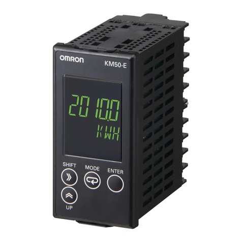
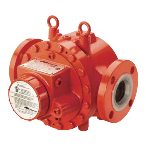
TechnipFMC 4728 User manual

Water Cut Monitor
Bulletin MNIN003 Issue/Rev 0.0 (5/19)
Installation / Operation Manual
4528 Detector, CX-645 Probe,
CSA Approved 4728 Monitor
MANUAL

Technical Support
Contact Information:
Field Service Response Center
24/7 Technical Support/Schedule a Technician: 1-844-798-3819
System Installation Supervision, Start-Up, and Commissioning Services Available
Customer Support
Contact Information:
Customer Service
TechnipFMC
FMC Technologies Measurement Solutions Inc.
1602 Wagner Avenue
Erie, Pennsylvania 16510 USA
P: +1 814 898-5000
F: +1 814 899-8927
measurement.solutions@TechnipFMC.com
TechnipFMC.com
Literature Library:
http://info.smithmeter.com/literature/online_index.html

Installation / Operation Manual
Table of Contents
Introduction................................................................................................................................................................................... 5
Specifications ............................................................................................................................................................................... 5
Percent Water Set Point ............................................................................................................................................................... 6
Time Delay ................................................................................................................................................................................... 6
Analog Output............................................................................................................................................................................... 6
4728.............................................................................................................................................................................................. 7
Model 4528 Detector – Types A, B, and C ................................................................................................................................... 8
Wiring Diagram............................................................................................................................................................................. 9
4-20 mA Loop ............................................................................................................................................................................. 10
Internal Powered................................................................................................................................................................. 10
External Powered................................................................................................................................................................ 10
Typical Applications .................................................................................................................................................................... 12
Typical Tank Flow Diagram......................................................................................................................................................... 13
Detector Calibration – 4528 0-5 VDE Output ............................................................................................................................. 14
Detector Calibration – 4528-X A with 4-20mA Module Mounted "Piggy Back" on Detector Card............................................... 15
Detector Information – Type B and C ......................................................................................................................................... 17
Installation Hints ......................................................................................................................................................................... 17
Troubleshooting.......................................................................................................................................................................... 18
Recommended Spare Parts ....................................................................................................................................................... 18
4728 with Explosion-proof Enclosure – Dimensional Drawing ................................................................................................... 19
4728 with Weather-proof Enclosure – Dimensional Drawing ..................................................................................................... 20
CX-645 Probe – Dimensional Drawing....................................................................................................................................... 21

Page intentionally left blank.

Installation / Operation Manual
Introduction
The 4728 S & W Monitor used in conjunction with a Model 4528 Detector Card and Model
CX-645 Probe, provides continuous on-line monitoring of percent water in crude oil.
The monitoring system measures changes in the product stream capacitance. The di-
electric constant (Dk) (a key factor in capacitance measurement) of the product stream
changes dramatically as water content varies. The change in capacitance is accurately
measured and correlated to percent water by calibration against “shake out” data.
The Model 4728 displays the percent water on a digital indicator and indicator status
lights continuously display the conditions measured by the system. Alarm relays and
a 4-20 mA output can be used to connect the system to other supervisory or control
elements.
Specifications
Input Power
115 VAC +/- 15%, 50/60 Hz, 2 watts
220 VAC (Optional)
14-28 Volts DC @ 130 mA
S&W Range
0-5%, 0-10%, or 0-20%
S&W Alarm Setpoint
0-100% of S&W Range
Input Signal
0-5V DC from 4528 Detector
Indicators
S&W / Setpoint LCD
Merchantable Oil LED, -Green
Excess S&W LED, -Red
Bypassing Oil LED, -Yellow
Outputs
4-20 mA analog
Relays
SPDT Relay, 10 Amp 250 VAC
1/2 Hp 250 VAC, 13A 120 VAC resistive
1/3 Hp 120 VAC, 10 A 30V DC resistive
Time Delay
0-90 seconds adjustable in 10 second steps.
Off delay approximately 10% of on delay time.
Temperature Range
-20°F to 160°F (-29°C to 71°C)
Enclosure
NEMA 4X, Fiberglass, water resistant
NEMA 7, Explosion Proof
Description Part Number
81001114
81001115
81001164

Percent Water Set Point
The Digital Indicator on the Model 4728 displays percent BS&W. The setpoint (BS&W
Limit) can be observed by moving the percent BS&W/Setpoint switch to the lower or
setpoint position. If it is desired to change the setpoint, rotate the setpoint adjust knob
until the new limit value is displayed. The switch must be held in the lower position while
performing this adjustment. When the switch is released the indicator will display the
percent water.
Time Delay
The delay that occurs between excess BS&W indication and bypassing, relay
transfer, is determined by the position of the time delay switch. The time is adjustable from
0-90 seconds in 10 second steps. The off delay, excess BS&W to merchantable oil, is
approximately 10 % of the on delay (30 sec. on, 3 sec. off).
Analog Output
The analog output is 4-20 milliamperes corresponding to 0-5%, 0-10%, 0-20% depending
on unit range. The 4-20 mA output function is accomplished by the use of a precision
integrated circuit. The 4 mA point may be adjusted slightly with the zero control on the
Model 4728. The 20 mA point is factory preset.
The Model 4728 utilizes a loop switch to determine whether the 4-20 mA loop will be
self powered or powered by a remote supply. In the internal mode the unit will drive
4-20 mA through a maximum loop resistance of 600 ohms. Loop resistance values of
>600 ohms are possible with an external power source.
In the external mode the current loop may be powered from an external power supply
(40 volts max.) through a 3 wire circuit. Maximum loop resistance will be
R loop = Vp - 13.5
.02
where Vp is the power supply voltage.
Note: Under no condition should power be applied to the “+” or “-” 4-20 mA terminals.
Circuit damage will occur. See page 7 for hookup.
Installation / Operation Manual

Installation / Operation Manual
4728
The functions and locations of these three blocks on the P.C. card are as follows:
(a) Left side - 110 V AC power input
(b) Bottom - Relay contacts
(c) Right side - Detector card connections, 4-20 mA hook-ups and 24 V DC power input
for DC operation of the 4728.
Note: Switch S1 which is located at the lower right of the P.C. card. The position of this
switch determines whether the 4-20 mA output is to be internally powered from the
4728, or externally powered from an outside source. Care must be taken to be sure
this switch is in its proper position BEFORE an external 4-20 mA loop power source
is connected. Failure to have the switch in the proper position may cause component
The function and operation of all other controls on the 4728 are as described in the
manual.

Installation / Operation Manual
Model 4528 Detector – Types A, B, and C
The Model 4528 Detector mounts in the explosion proof conduit on the capacitance
probe. It converts water changes in the oil flowing through the probe to an output volt-
age that varies with the water.
The output will be 0-5 volts regardless of the range of the detector (i.e. 0-5%, 0-10%,
0-20%). To mount the detector in the condulet the top aluminum plate must be removed.
This can be accomplished by removing the three screws marked “A” in the above draw-
ing and gently lifting the top plate off of the printed circuit board. Find the short white
or red wire with the clip on it and gently pull the wire straight up. Remove the nut from
screw “B”. Insert the printed circuit board into the condulet. Position the board so the
rod sticking up from the probe goes into the round hole on the printed circuit board,
just below the “Probe” - “Ref” Switch. Center the P.C. Card over the mounting holes
and insert screw “B”. Push the clip on the end of the white or red wire down firmly on
the rod coming up from the probe. Rotate the clip if necessary. Replace aluminum top

plate by using the three screws marked “A” on the drawing.
Wiring Diagram
Note: Spade Lugs are not used on CSA Approved Model 4728.
Note: Typical Interconnecting cable between Detector and Readout.
Maximum recommended length is 300 feet.
Installation / Operation Manual

Installation / Operation Manual
4-20 mA Loop
Warning: Loop Switch MUST be up in external position BEFORE connecting external
power on 4728 with bottom terminal strip. Loop Switch MUST be up before connecting
external power on CSA Approved Model 4728 with the two sides and bottom terminal
strips.

Installation / Operation Manual
The probe is constructed of two concentric tubes. Wetted and internal surfaces are
coated with a fused epoxy powder. The inner tube is insulated from the outer tube by
PTFE (polytetrafluoroethylene) spacers and is electrically connected to a terminal within
the sensor housing. The internal element spacers can be fitted with trimmer rods should
it be necessary to adjust the base capacitance.
Nominal
Pipe Size
Catalog Model
Number
Stock
Number
2"
3"
4"
6"
CX-645-200-BGP
CX-645-300-BGP
CX-645-400-BGP
CX-645-600-BGP
81001190
81001195
81001200
81001205
2"
3"
4"
6"
CX-645-200-BFP
CX-645-300-BFP
CX-645-400-BFP
CX-645-600-BFP
81001191
81001196
81001201
81001206
2"
3"
4"
6"
CX-645-230-BGP
CX-645-330-BGP
CX-645-430-BGP
CX-645-630-BGP
81001192
81001197
81001202
81001207
2"
3"
4"
6"
CX-645-260-BGP
CX-645-360-BGP
CX-645-460-BGP
CX-645-660-BGP
81001193
81001198
81001203
81001208
Note: Field Conversion kit to modify Model CX-201 Probes to CX-645 configuration
available. Stock No. 49020402
Pipe Sizes Available
Pipe Size Dim. "A"
2" 17"
3", 4", 6", 8" 32"

Installation / Operation Manual
Typical Applications
Percent Water Indication
In this application the Indicating Unit provides percent
water reading on the front panel. The Indicating Unit
maybe located near the Measuring Unit or at a remote-
central control room.
Percent Water Indication and Pneumatic Control
In this application an analog to air converter may be
mounted adjacent to or remote from the Indicating Unit
housing. A 3-15 psi pneumatic output signal is provided
directly proportional to the percent water in the process.
Percent Water Recording
In this application the Indicating Unit provides
local reading on an indicating meter and provides an
analog output signal to a standard recorder. In place of
the recorder this output could be connected to a meter,
computer input, or any other DC input device.
Percent Water Indication and Set-Point Control
In this application the adjustable alarm may be used to
operate a diverter valve should the water content exceed
a preset percentage. Local indication is provided and an
analog output for other indication and control functions
is available.
Percent Water Indication
In this application the Model 4528-5A Detector only is
used to provide an analog output proportion to water
cut. The 4728 Indicating Unit is not required.

Installation / Operation Manual
Typical Tank Flow Diagram

Installation / Operation Manual
Detector Calibration – 4528 0-5 VDC Output
In July 1993 the 4528 Detector was changed to no longer have a negative output. An empty probe or low Dk will
cause the unit to read zero. A shortened probe or a probe full of water will read bad oil. The coarse and fine adjust-
ments were changed from variable capacitors to 25 turn pots. The single four point terminal strip on the bottom of
the P.C. Card was changed to two colored two point connectors.
Calibration 4528 Detector 0-5%
1. Connect power and probe detector chassis/indicator unit as shown on the interconnecting wiring diagram.
2. Turn on power/system to cause oil to flow through probe. Allow flow to stabilize.
3. Take grindout of water in oil. For calibration purposes the oil should preferably have less than 1% water in it.
4. Apply power to Model 4728 indicator unit. Ignore lights until calibration is complete.
5. A. 4528 Detector
1. Set probe/ref. switch at top of chassis to probe position.
2. Set DC volt meter on 0-10 volt scale. Insert leads into test jacks on detector face or watch digital
readout on face of Model 4728 indicator unit.
3. Turn the fine zero (marked ZERO F) clockwise (CW) 25 turns until the pot is fully CW. Full clockwise
is indicated by a “clicking” feel and sound when the pot is turned.
4. Turn the fine zero back counter clockwise (CCW) approximately 10 turns.
5. Turn the coarse zero pot (marked ZERO C) 25 turns full counter clockwise. Listen for clicks.
6. Turn the coarse zero CW until the reading is at or near the grindout value. Do not tune through zero.
Always approach the grindout value from the CW direction.
7. Next, turn the fine zero to get complete agreement of the displayed reading to the grindout value.
For example if the grindout was 0.3, then the volt meter/indicator should read 0.3.
Note: Due to calibration differences, the volt meter and indicator readings may not read exactly the same.
8. Move Probe/Ref. switch to Ref. position.
9. Adjust span control to make reading show 5.00 higher than the grindout. (i.e. if grindout was .3 span
control is adjusted to show reading of 5.30.)
10. On a 10% Detector turn COARSE/FINE tuning adjustments as required to make voltmeter read 1/2 the
water cut.
11. On a 20% Detector turn COARSE/FINE tuning adjustments as required to make voltmeter read 1/4 the
water cut.
Remove volt meter. Move Probe/Ref. switch to probe position.
6. A. 4728 Readout Unit
1. Pull and hold the S&W/Set Point Switch down. Turn set point adjust knob to obtain reading at which
monitor is to divert. Release switch.
2. Turn the time delay switch in lower right with a small screwdriver to set time delay for output relay to
actuate after excess S&W light comes on. Multiply number in window above screwdriver slot by 10 to
get time delay in seconds.
7. Calibration is complete.

Installation / Operation Manual
Detector Calibration – 4528-X A with 4-20mA Module Mounted "Piggy Back" on
Detector Card
1. A. Calibration 4528-X A With 4-20 mA Module Mounted “Piggy Back” on Detector Card
1. Remove Detector aluminum face plate by removing the three 6-32 mounting screws and the bottom screw
on P.C. Card.
2. Mount the P.C. Card in the condulet by using the short screws removed from the Detector assembly. Be sure
screws for future use.
3. Connect 24 V.D.C. to the left terminal block of the detector. Observe polarity. Press clip (on probe wire) onto
the stud coming into condulet from probe.
4. Turn on power/system to cause oil to flow through the probe. Allow flow to stabilize. For calibration
purposes the oil should preferably have less than 1% water in it.
5. Set Probe/Ref. switch at top of chassis to probe position.
6. Set a DC volt meter to 0-10 volt scale. Insert leads into test jacks on detector face.
7. Turn the Fine Zero (marked ZERO F) clockwise (CW) 25 turns until the pot is fully CW. Full clockwise
is indicated by a “clicking feel and sound when the pot is turned.
8. Turn the fine zero back counter clockwise (CCW) approximately 10 turns.
9. Turn the coarse zero pot (marked ZERO C) 25 turns full counter clockwise. Listen for clicks.
10. Turn the coarse zero CW until the volt meter reads 0.00 to 0.05. Do not turn pot past point where
numbers stop getting smaller.
11. Next, turn the fine zero to get as small a reading possible on volt meter.
12. Move Probe/Ref. switch to Ref. position.
13. Adjust output span control to make volt meter show 5.00 volts.
14. Move Probe/Ref. switch to Probe position.
15. Remove volt meter leads from test sockets. Turn volt meter to milliampere setting and connect leads
to “signal” terminals.
16. Adjust the single, small blue pot (R1) on piggy-back module to get reading of 4 mA on meter.
the short screws at the middle and bottom.
18. Remove volt meter leads from signal terminals. Turn volt meter back to voltage setting and insert
leads into red and black sockets.
19. Run a “shake-out” of oil going through probe to determine amount of water in it.
20. On a 5% Detector turn COARSE/FINE tuning adjustments as required to make voltmeter read the
water cut.
21. On a 10% Detector turn COARSE/FINE tuning adjustments as required to make voltmeter read 1/2 the
water cut.
22. On a 20% Detector turn COARSE/FINE tuning adjustments as required to make voltmeter read 1/4 the
water cut.
23. Remove volt meter.
24. Connect field wiring as required to the signal terminals for 4-20 mA output.

Installation / Operation Manual
Notes:
1. This procedure initially sets the detector with 0-5 volts to which you adjust the 4-20 mA output, then the
reading is offset to match the amount of water in the oil in the probe.
2. The 4-20 mA loop is internally powered from the 4528-A. DO NOT USE an external loop power source.
The 4528-5A Detector Card is designed to supply a 4-20 mA signal direct to an external readout device. It
is not designed to be used with a Model 4728 Readout Unit.
3. Maximum Loop Resistance is 250 ohms.
4. Shielded, twisted pair wire is recommended for the 4-20 mA output. Ground the shield at one end of the
5. Starting in mid-year 2000, the 4 mA pot adjusting screw will be accessible through a hole, just to the
right of the “test” wording, for adjustment without removing the aluminum detector face plate. Be aware
that this adjusts the 4 mA only, the 20 mA is automatically adjusted electronically.

Installation / Operation Manual
Detector Information – Type B and C
Type “C” Detector with Fail-safe Switch - This switch allows the output from the Detector
Chassis to be tailored to the requirements of the customer.
The Fail-safe Switch is located on the upper right side of the printed circuit board under
the cover plate. The normal position of the switch is in the Low Fail-safe position and
is so shipped from the factory. Due to the functionality of the detector output when in
the High Fail-safe position, care should be observed when using it to prevent possible
undesired readings.
Below is a chart showing the detector output under certain conditions with the switch
in either the low or high Fail-safe position:
Conditions Low Fail-Safe High Fail-Safe
Overrange
Underrange
Open Probe
Shorted Probe
Note: All voltage readings are DC volts taken on the SIG+ and SIG- Terminals of the
4528 Chassis.
Overrange - Approximately two times S&W range of the chassis.
Underrange - Approximately 2% below zero.
Open Probe - Chassis Pickup wire is not connected to the probe.
Shorted Probe - Occurs when electrical short exists in the probe.
Installation Hints
• Always install probe up stream of dump valve anytime probe is mounted on oil line
coming off treater, separator, etc... Never install downstream as gas will break out
to some degree as oil goes from vessel pressure to lower line pressure after dump
valve. These gas bubbles will be irregular in size and volume as oil flows through
probe. Erratic monitor readings will result.
• Vertical flow through probe is recommended. Either up or down, but not horizontal.
Water often will drop out of oil unless the flow velocity is very high, and if the probe
is mounted horizontally in a slightly low spot, water will build up in probe with result-
ing erroneous readings.
• Always locate the oil sample removal point as close as possible to the probe. Pref-
erably downstream of and below probe in elevation. Failure to have sample point
and measuring point (probe) in close proximity can result in water measurement
inaccuracies which often are flow rate sensitive.
• L.A.C.T. Systems should always have back pressure valves on both the “good” and
“bad” oil lines leading from the L.A.C.T. Constant pressure on the oil in the probe
is essential for close measurement.

Installation / Operation Manual
Troubleshooting
Problem Possible Cause
probe, but are steady during
a steady amount of water.
2. Restricted suction to charge pump on L.A.C.T.
over a period of time (some-
consistent.
-
-
the probe stud to ground for resistance and capaci-
tance readings after removing the detector chasis.
-
-
4728.
No output from 4528 detec-
1. No power or probe wire not attached to probe
stud.
Note:
position and the probe wire is not attached to the
probe.
Recommended Spare Parts
1. 1/2 amp slo-blo fuses p/n 68108327
2. Relay p/n 36017183
3. Detector
0-5% p/n 81001164
0-10% p/n 81001160
0-20% p/n 81001161
0-5% (4-20mA) p/n 81001295
0-20% p/n 81001296

Installation / Operation Manual
4728 with Explosion-proof Enclosure – Dimensional Drawing

Installation / Operation Manual
4728 with Weather-proof Enclosure - Dimensional Drawing
This manual suits for next models
4
Table of contents
Other TechnipFMC Measuring Instrument manuals
TechnipFMC
TechnipFMC Smith Meter C2 User manual

TechnipFMC
TechnipFMC Smith Meter Genesis Series User manual
TechnipFMC
TechnipFMC Smith Meter Ultra C Series Operating and safety instructions
TechnipFMC
TechnipFMC Smith Meter PRIME 4 User manual

TechnipFMC
TechnipFMC Smith Meter User manual

TechnipFMC
TechnipFMC Proline Promass E 500 Instruction Manual

TechnipFMC
TechnipFMC Smith Meter MMRT User manual

TechnipFMC
TechnipFMC Smith Meter Instruction manual

TechnipFMC
TechnipFMC Smith Meter AccuLoad IV Series Manual

TechnipFMC
TechnipFMC Smith Meter JB10 S1 User manual