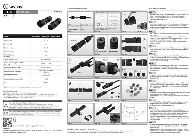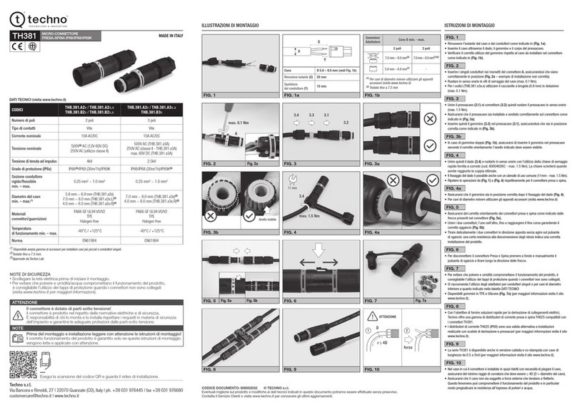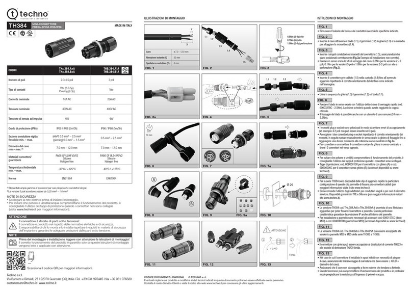
Strip the cable a length of 0.788 inches
(20 mm) (Fig. 2.1)
In case of screw connection
(PN: THB.385.xxx) strip the wires a
length of 0.315 inches (8 mm) and twist
them together (Fig. 2.1)
In case of piercing screw connection (PN:
THP.385.xxx) do not strip the wires (Fig.
2.2)
Connect the wires to the male connector
insert (or female connector insert) with a
screw driver.
Screws must be closed using a torque of
0.8 Nm for pressure wire
Insert the male connector insert in the
housing until it stop. Make sure the
connector insert’s protrusion match
with the housing’s cavity until you hear
a “click”
The female connector insert and the
male connector insert can be inserted in
both connector housings (male or
female) depending on the application
needs.
Firstly create a hole in the mounting
surface with Ø25 for the linear (Fig. 7.1)
and Ø20 for 90° version (Fig. 7.2)
Secondly, tighten the lock nut using the
appropriate tool to a torque of 2.5 Nm
and 4 Nm
Set-up of the female connector: (a)
Pressure nut, (b) locking nut,
(c) cable seal, (d) connector housing, €
connector insert (male or female)
Unscrew the pressure nut till it comes
out from the connector housing (Fig.
9.1).
Pull out the locking nut from the
connector housing (Fig. 9.2).
Choose the cable seal and the cable
adapter according to the cable diameter
(Fig. 10.1).
Push the pressure nut and the cable seal
over the cable (Fig. 10.2).
Insert the cable in the female connector
housing (Fig. 10.2). Do not insert the
cable nut and seal in the connector
housing.
Strip the cable a length of 0.788 inches
(20 mm) (Fig. 11.1)
In case of screw connection
(PN: THB.384.xxx) strip the wires a
length of 0.315 inches (8 mm) and twist
them together (Fig. 11.1)
In case of piercing screw connection
(PN: THP.384.xxx) do not strip the wires
(Fig. 11.2)
