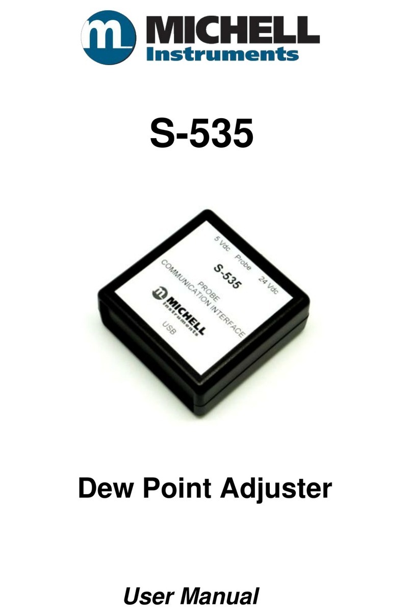
Technoton MasterCAN CC User manual

Content
MasterCAN Vehicle Data Interfaces. Operation manual. Version 4.0
© Technoton, 2017 2
Content
Revision history......................................................................................................... 4
Terms and Definitions ................................................................................................ 5
Introduction.............................................................................................................. 6
1 General information and technical specifications ......................................................... 8
1.1 Purpose of use and application area .................................................................... 8
1.2 Delivery set.................................................................................................... 10
1.3 Exterior view and design .................................................................................. 11
1.3.1 Exterior view and design MasterCAN CC ....................................................... 11
1.3.2 Exterior view and design MasterCAN C 232/485 ............................................ 12
1.3.3 Exterior view and design MasterCAN V-GATE ................................................ 13
1.4 Operation principle.......................................................................................... 14
1.5 Technical specifications.................................................................................... 15
1.5.1 Main Performance Specifications ................................................................. 15
1.5.2 MasterCAN CC input and output interfaces ................................................... 16
1.5.3 MasterCAN C 232/485 input and output interfaces ........................................ 18
1.5.4 MasterCAN V-GATE input and output interfaces............................................. 19
1.6 Dimensions .................................................................................................... 20
2 MasterCAN connection ........................................................................................... 21
2.1 Exterior inspection prior to starting works .......................................................... 21
2.2 Operational restrictions.................................................................................... 22
2.3 Electrical connection........................................................................................ 23
2.3.1 Using Crocodile contactless reader devices to connect MasterCAN input ........... 24
2.3.2 MasterCAN CC connection .......................................................................... 25
2.3.3 MasterCAN C 232/485 connection ............................................................... 27
2.3.4 MasterCAN V-GATE connection ................................................................... 28
2.4 Serviceability check......................................................................................... 30
2.5 Using MasterCAN as a summator of DUT-E CAN fuel level sensors........................ 31
3 MasterCAN configuration with the service kit ............................................................ 32
3.1 SK MasterCAN application ................................................................................ 32
3.2 Hardware requirements ................................................................................... 33
3.3 Service kit delivery set .................................................................................... 34
3.3.1 Exterior view and delivery set ..................................................................... 34
3.3.2 Universal service adapter ........................................................................... 35

Content
MasterCAN Vehicle Data Interfaces. Operation manual. Version 4.0
© Technoton, 2017 3
3.3.3 USB A-B Cable .......................................................................................... 36
3.3.4 MasterCAN CC, MasterCAN C 232/485, MasterCAN V-GATE service cable ......... 37
3.3.5 MasterCAN Diagnostic service cable............................................................. 38
3.4 Service kit connection...................................................................................... 39
3.4.1 Exterior inspection prior to connection ......................................................... 39
3.4.2 Operation restrictions ................................................................................ 40
3.4.3 Connecting MasterCAN to PC ...................................................................... 41
3.5 Operation check.............................................................................................. 43
3.6 Service MasterCAN software operation............................................................... 44
3.6.1 User authorization..................................................................................... 44
3.6.2 Working with MasterCAN profile .................................................................. 45
3.6.3 MasterCAN settings ................................................................................... 47
3.6.4 MasterCAN firmware upgrade ..................................................................... 49
4 Storage ............................................................................................................... 51
5 Transportation...................................................................................................... 52
6 Utilization/re-cycling ............................................................................................. 53
Contacts................................................................................................................. 54
Annex A Register map of Modbus output messages of MasterCAN.................................. 55
Annex B MasterCAN C 232/485 and MasterCAN V-GATE text message protocol ............... 59
Annex C MasterCAN connection scheme to summarize several DUT-E CAN readings......... 62

Revision history
MasterCAN Vehicle Data Interfaces. Operation manual. Version 4.0
© Technoton, 2017 4
Revision history
Version
Date
Editor
Description of changes
1.0
01.2013
OD
Basic version.
4.0
01.2017
OD
New design of output connectors for all models of MasterCAN.
MasterCAN scheme of connection to terminal changed.
Delivery set of MasterCAN and SK MasterCAN changed.
S6 SK service kit can now be used for MasterCAN configuration.
MasterCAN connection to PC is changed and amended.
MasterCAN V-gate connection parameters are clarified.
MasterCAN data transfer protocol is amended.
Terms and definitions are updated.

Terms and Definitions
MasterCAN Vehicle Data Interfaces. Operation manual. Version 4.0
© Technoton, 2017 5
Terms and Definitions
S6 —is the vehicle onboard data bus developed by JV Technoton to enable
integrating the GPS/GLONASS-based vehicle monitoring system into the
vehicle electrical equipment. It comprises a set of cables, interfaces and
protocols. Physically, it is based on CAN 2.0B (ISO 11898-1:2003) and K-Line
(ISO 9141). S6 bus data exchange protocol complies with SAE J1939 International
Standard.
To get more details on S6 telematics bus visit http://s6.jv-technoton.com/en/
Telematics interface S6 operation manual contains guidelines and rules which refer to S6
cabling system, S6 SK service kit and service software for S6 Telematics Interface
PGN (Parameter Group Number) —is a combined group of S6 parameters, which has
common name and number. Functional Modules (FM) of the Unit can have input/output
PGNs and setup PGNs.
SPN (Suspect Parameter Number) —informational unit of S6. Each SPN has determined
name, number, extension, data type and numerical value. The following types of SPN exist:
Parameters, Counters, Events. SPN can have a qualifier which allows qualification of
parameter’s value (e.g. – Onboard power supply limit/Minimum).
J1708 is a digital bus-type interface. Bus J1708 is used in some modern vehicles to
transmit and exchange data between the engine controller and other electronic devices. The
level of data presentation complies with SAE J1587 International Standard.
FMS are data packets of vehicles’digital onboard interfaces (further
on
vehicles) that comply with the document FMS-Standard Interface
Description (further on —FMS-Standard).
FMS-Standard is an open FMS
Interface Standard developed by world leading
truck manufacturers.
More detailed description of FMS messages is described in FMS-Standard Interface
description document. Actual version of the document can be downloaded from the web site
of developer http://www.fms-standard.com.
Telematics —special set of telematics messages developed by Technoton. Meets
requirements of SAE J1939/71 standards. Telematics messages contain important operation
parameters of vehicle.
Onboard equipment (OE) —Telematics System Elements, directly installed in vehicle.
Telematics terminal (Tracking device) is a unit of Telematics System used for reading the
signals of Vehicle standard and additional sensors, getting location data and transmitting
the data to the Server.
Telematics system —complex solution for real-time and after trip vehicle monitoring and
control. Main vehicle parameters monitored: route, fuel consumption, operation time,
technical condition of vehicle, safety. Consists of OE, Communication channels, Telematics
service ORF 4.
Vehicle —an object controlled within Telematic system. Usually Vehicle means a truck,
tractor or bus, sometimes a locomotive or river boat. From Telematic system point of view,
stationary objects are also considered to be vehicles: diesel gensets, stationary tanks,
boilers/burners.
Unit —an element of Onboard Equipment of Vehicle, which is connected to Telematics
Interface S6.

Introduction
MasterCAN Vehicle Data Interfaces. Operation manual. Version 4.0
© Technoton, 2017 6
Introduction
Recommendations and guidelines contained in this Operation Manual are related to
MasterCAN Vehicle Data Interfaces (hereinafter MasterCAN) and SK MasterCAN service kit
developed by TECHNOTON JV, Minsk, BELARUS.
This document contains information on MasterCAN design, principle of operation,
specifications as well as recommendations on its installation and operation. The document
also defines SK MasterCAN connection and operation as well as manual on the included
Service MasterCAN software (version 3.2 and newer).
—is a tool for Telematics systems designed for safe and
uninterruptible data gathering from onboard information buses of global leading Vehicle
manufacturers.
SK MasterCAN provides communication between PC and MasterCAN units for their
configuration.
MasterCAN features:
comply with national and European automobile standards;
easy integration with vehicle Telematics systems;
safe data integration from one or several onboard information buses to S6
Telematics interface *;
simplifies setting-up of Telematics terminal by sifting unnecessary data
simple input connection using Crocodile contactless readers
and ;
automatic trip fuel consumption counter, incremented by hourly fuel consumption
rate from onboard CANbus **
power supply from the vehicle onboard power supply system without any additional
power supply units.
*MasterCAN CC and MasterCAN V-GATE.
** For MasterCAN CC firmware v.8 and higher and for MasterCAN C 232/485 and
MasterCAN V-gate firmware v.7 and higher

Introduction
MasterCAN Vehicle Data Interfaces. Operation manual. Version 4.0
© Technoton, 2016 7
MasterCAN modifications:
MasterCAN CC for receiving data from onboard CAN interface, converting received
data and sending created FMS and Telematics messages to CAN/S6 interface;
MasterCAN C 232/485 for receiving data from onboard CAN interface, converting
received data and sending created messages to RS-232 and
RS-485 interfaces;
MasterCAN V-GATE for receiving data from onboard CAN and J1708 interfaces
simultaneously, converting received data and sending created FMS and Telematics
messages to CAN/S6 interface and messages to RS-232 interface.
MasterCAN modifications are designated in accordance with table 1.
Table 1 —MasterCAN modifications
Vehicle Data Interface
Xsymbol
standing for
MasterCAN
modifications
Input interface
(Protocol)
Output Interface
(Protocol)
CC
CAN (SAE J1939)
CAN/S6 (SAE J1939)
C 232/485
CAN (SAE J1939)
RS-232 and RS-485
(ASCII/Modbus/DUT-E COM)
V-GATE
CAN (SAE J1939)
and J1708 (SAE J1587)
CAN/S6 (SAE J1939) and RS-232
(ASCII/Modbus/DUT-E COM)
To ensure proper operation, MasterCAN should be connected and configured by
certified professionals who have successfully finished manufacturer’s technical training.
For MasterCAN configuration service kits SK MasterCAN and S6 SK can be used (purchased
separately).
ATTENTION: The Manufacturer guarantees MasterCAN compliance with the
requirements of technical regulations subject to the conditions of storage,
transportation and operation set out in this Manual.
Manufacturer reserves the right to modify MasterCAN specifications that do not lead
to a deterioration of the consumer qualities without prior customer notice.

General information and technical specifications / Purpose of use and application area
MasterCAN Vehicle Data Interfaces. Operation manual. Version 4.0
© Technoton, 2017 8
1 General information and technical specifications
1.1 Purpose of use and application area
are designed for information Vehicle buses data
processing and generation of information ready for use by Telematics systems.
Application area of MasterCAN - is used within Telematics systems.
MasterCAN in combination with contactless readers CANCrocodile and 1708Crocodile can be
used as convenient solution for data integration form onboard CANbuses and 1708buses to
Telematics system (see figure 1).
MasterCAN analyzes information from automotive information buses, filters out excess data
and generates output messages containing tens of most important operation parameters of
Vehicle (e.g. instant and trip fuel consumption, total fuel consumption, RPMs, fuel level,
engine operation time, engine temperature, oil pressure and level).
MasterCAN output messages are received by Telematics terminal which collects, records,
stores and transmits data to Server. Software on the Server processes, analyzes received
data and generates reports containing data on fuel consumption and parameters of Vehicle
operation.
MasterCAN in combination with Crocodile is also a convenient solution for data gathering
from sensors and peripheral devices of one or several onboard CAN (J1708) buses and data
transfer to S6 Telematics interface. This allows to monitor various Vehicle operation
parameters via just one CAN-port of Telematics terminal (see figure 2).
Figure 1 –On-board CAN and J1708 buses data integration in Telematics interface

General information and technical specifications / Technical specifications / MasterCAN CC input and output interfaces
MasterCAN Vehicle Data Interfaces. Operation manual. Version 4.0
© Technoton, 2017 9
Figure 2 –On-board automotive CANbus data transmission to S6 Telematics interface
Reports based on MasterCAN data allow monitoring of instant Vehicle fuel consumption rate
as well as fuel volume consumed during trip (see figure 3)
Figure 3 –Automotive CANbus data monitoring through MasterCAN
Data based on CANbus
Graph of instant fuel consumption
based on CANbus data

General information and technical specifications / Delivery set
MasterCAN Vehicle Data Interfaces. Operation manual. Version 4.0
© Technoton, 2017 10
1.2 Delivery set
1MasterCAN vehicle data interface –1 pc.;
2Specification with factory settings sheet –1 pc.;
3MasterCAN MK VDI mounting kit (1 pc.) including:
a) molex connector, 4 pins - 2 pcs.;
b) molex connector, 6 pins - 2 pcs.;
c) contact pin - 5 pcs.;
d) fuse with holder (2 A) - 1 pc.;
e) wire - 17 pcs.;
f) S6 CW plug *- 2 pcs.;
g)cable tie - 20 pcs.
Figure 4 —MasterCAN delivery set
*Includes embedded termination resistor 120 Ohm.
1
3e
2
3f
3d
3c
3b
3a
3g

General information and technical specifications / Exterior view and design / Exterior view and design MasterCAN CC
MasterCAN Vehicle Data Interfaces. Operation manual. Version 4.0
© Technoton, 2017 11
1.3 Exterior view and design
1.3.1 Exterior view and design MasterCAN CC
1- casing;
2- input CAN connector to connect to onboard CANbus;
3- red CAN1 LED indicating data reception;
4- red CAN2 LED indicating data transmission;
5- green Power LED indicating power supply is turned on;
6- output S6 connector for connection to S6 Telematics interface;
7- RS232/485 connector *;
Figure 5 —MasterCAN CC exterior view and design
*Not used for MasterCAN CC.
1
3
2
4
6
7
5

General information and technical specifications / Exterior view and design / Exterior view and design MasterCAN C 232/485
MasterCAN Vehicle Data Interfaces. Operation manual. Version 4.0
© Technoton, 2017 12
1.3.2 Exterior view and design MasterCAN C 232/485
1- casing;
2- input CAN connector to connect to the onboard CANbus;
3–red CAN1 LED indicating data reception;
4- red RS232 LED indicating data transmission;
5- red RS485 LED indicating data transmission;
6- green Power LED indicating power supply is turned on;
7- output S6 connector for connection to S6 Telematics interface;
8- output RS232/485 connector for connection to
RS-232/RS-485
-ports
of Telematics terminal.
Figure 6 —MasterCAN C 232/485 exterior view and design
*For power supplying and configuring MasterCAN C 232/485.
1
3
2
4
5
7
8
6

General information and technical specifications / Exterior view and design / Exterior view and design MasterCAN V-GATE
MasterCAN Vehicle Data Interfaces. Operation manual. Version 4.0
© Technoton, 2017 13
1.3.3 Exterior view and design MasterCAN V-GATE
1- casing;
2- input CAN connector to connect to the onboard CANbus;
3- input J1708 connector to connect to the onboard J1708 bus;
4- red CAN1 LED indicating data reception;
5- red CAN2 LED indicating data transmission;
6- red RS232 LED indicating data transmission;
7- red J1708 LED indicating data reception;
8- green Power LED indicating power supply is turned on;
9- output S6 connector for connection to S6 Telematics interface;
10 - output RS232/485 connector for connection to
RS-232
-port
of Telematics terminal.
Figure 7 —MasterCAN V-GATE exterior view and design
1
2
3
4
5
9
10
6
7
8

General information and technical specifications / Operation principle
MasterCAN Vehicle Data Interfaces. Operation manual. Version 4.0
© Technoton, 2017 14
1.4 Operation principle
MasterCAN automatically and continuously receives data from CAN onboard bus via
J1939 protocol (MasterCAN CC, MasterCAN C 232/485 and MasterCAN V-GATE
modifications), or from J1708 onboard bus via J1587 protocol (MasterCAN V-GATE
modification). Additionally, MasterCAN V-GATE can receive data from CANbus and J1708
bus simultaneously.
MasterCAN analyzes received data and sorts out the most needed data on vehicle
operation parameters, generates messages (PGN) and sends them to CAN/S6 output
interface in accordance with 1.5.2-1.5.4.
Messages contained in signals of MasterCAN LED indicators during its operation are
identified in accordance with their description in table 2.
Table 2 - Messages contained in signals of MasterCAN LED indicators
LED indicator
Description
Designation
Indicator status
and light color
CAN1
Data reception from CANbus is on
No signal
No data reception from CANbus
CAN2
Outgoing messages transmission to
CAN/S6 interface is on
No signal
No outgoing messages are
transmitted
to CAN/S6 interface
RS232
Transmission of messages to
RS-232
interface is on
No signal
No messages are transmitted to
RS-
232 interface
RS485
Transmission of messages to
RS-485
interface is on
No signal
No messages are transmitted to
RS-
485 interface
1708
Transmission of data of J1708 bus
is
on
No signal
No transmission of data of J1708 bus
Power
Power is on
No signal
Power is off (or the supplied
voltage
value is less than
minimally allowed)

General information and technical specifications / Technical specifications / Main Performance Specifications
MasterCAN Vehicle Data Interfaces. Operation manual. Version 4.0
© Technoton, 2017 15
1.5 Technical specifications
1.5.1 Main Performance Specifications
Table 3 —Basic performance specifications of MasterCAN
Specification, Unit of Measurement
Value
Supply voltage range, V
from 10 to 45
Current consumption at nominal voltage 12 V, mA, not more
than
100
Current consumption at nominal voltage 24 V, mA, not more
than
50
Ambient air temperature, °C
from -40 to +85
Level of casing protection
IP40
Dimensions, mm, not more than
see figure 8
Weight, kg, not more than
0.15

General information and technical specifications / Technical specifications / MasterCAN CC input and output interfaces
MasterCAN Vehicle Data Interfaces. Operation manual. Version 4.0
© Technoton, 2017 16
1.5.2 MasterCAN CC input and output interfaces
MasterCAN CC input interface is used to receive data from the onboard CANbus.
It’s physically based on CAN 2.0B interface. Data reception is carried out automatically
(default mode) or on request.
MasterCAN CC input interface signals comply with SAE J1939 international standard.
CAN/S6 output interface is used for transmission of useful information to Telematics
terminal. Data transmission protocol is based on SAE J1939 and correspond to S6 Database
(see details at http://s6.jv-technoton.com).
MasterCAN CC sends Telematics and FMS messages to CAN/S6 interface (see table 4).
Output messages can be selected through Service MasterCAN software.
Detailed description of FMS messages is contained in the document ―FMS-Standard
Interface Description‖. The current version of this document can be downloaded at the
developing company website at: http://www.fms-standard.com.
MasterCAN CC has unique not editable network address 122 which is used for device
identification through input and output interfaces.
Table 4 —Output messages of MasterCAN to CAN/S6 interface
PGN
Short message description
Telematics
63233
Message 1
63234
Message 2
63235
Message 3
63236
Message 4
FMS
61440
Electronic retarder controller 1
61443
Electronic engine controller 2
61444
Electronic engine controller 1
61445
Electronic transmission controller 2
64777
High resolution fuel consumption (liquid)
64932
PTO drive engagement
64933
Door control 2
64977
FMS-standard interface identity/Capabilities
65102
Door control 1
65110
Aftertreatment 1 diesel exhaust fluid tank 1 information
65112
Air suspension control 4
65131
Driver's identification

General information and technical specifications / Technical specifications / MasterCAN CC input and output interfaces
MasterCAN Vehicle Data Interfaces. Operation manual. Version 4.0
© Technoton, 2017 17
Table 4 continued
PGN
Short message description
65132
Tachograph
65136
Combination vehicle weight
65198
Air supply pressure
65216
Service information
65217
High resolution vehicle distance
65237
Alternator information
65253
Engine hours, revolutions
65254
Time/Date
65257
Fuel consumption (liquid)
65258
Vehicle weight
65260
Vehicle identification
65262
Engine temperature 1
65265
Cruise control/Vehicle speed 1
65266
Fuel economy (liquid)
65269
Ambient conditions
65276
Dash display
Notes
1 The content of MasterCAN output messages depends on the data gathered from CANbus
(J1708 bus). This data may differ depending on make, model and year of the Vehicle equipped.
2 MasterCAN automatically increments trip fuel consumption counter, calculating it from ―Hourly
fuel consumption‖ (SPN 183) and stores calculated values inside internal memory until powering
off. Step of trip fuel consumption counter incrementation is 0.5 l. If standard
PGN 65257, which contains ―Volume of fuel consumed in a trip‖ (SPN 182) and/or ―Fuel
consumption by engine‖ (SPN 250), is transmitted over a CANbus, this standard PGN will have
higher priority and will be transmitted to the output of MasterCAN without any changes.

General information and technical specifications / Technical specifications / MasterCAN C 232/485 input and output interfaces
MasterCAN Vehicle Data Interfaces. Operation manual. Version 4.0
© Technoton, 2017 18
1.5.3 MasterCAN C 232/485 input and output interfaces
MasterCAN C 232/485 input interface is used to receive data from the onboard CANbus.
It’s physically based on CAN 2.0B interface. Data reception is carried out automatically
(default mode) or on request.
MasterCAN C 232/485 input interface signals comply with SAE J1939 international standard.
MasterCAN 232/485 has unique not editable network address 124 which is used for device
identification through input interface.
MasterCAN C 232/485 output interface is used for transmission of useful information to
Telematics terminal. It’s physically based on RS-232 and
RS-485 interfaces.
By default, MasterCAN C 232/485 transmits text messages per ASCII standard through RS-
232 and RS-485 interfaces. Description of text messages transmission protocol can be
found in annex B.
Service MasterCAN software allows selecting ―request-response‖ mode (operating on
Modbus protocol, see 3.6.3) for output text messages transmission. Modbus protocol allows
transmission of wider set of Vehicle parameters (see annex A).

General information and technical specifications / Technical specifications / MasterCAN V-GATE input and output interfaces
MasterCAN Vehicle Data Interfaces. Operation manual. Version 4.0
© Technoton, 2017 19
1.5.4 MasterCAN V-GATE input and output interfaces
Input interfaces of MasterCAN V-GATE:
CAN –for data reception from automotive CANbus. Physically based on CAN 2.0B
interface. Data reception is carried out automatically (default mode) or on request.
Input signals characteristics corresponds to SAE J1939 standard.
J1708 —for data reception from automotive J1708bus. Data reception is carried out
automatically. Input signals characteristics corresponds to SAE J1587 standard.
Output interfaces of MasterCAN V-GATE:
CAN/S6 —for transmission of useful information to Telematics terminal. Data
transmission protocol is based on SAE J1939 and correspond to S6 Database
(see details at http://s6.jv-technoton.com).
MasterCAN V-GATE transmits Telematics and FMS messages to CAN/S6 interface
similarly to MasterCAN CC (see 1.5.2). Output messages can be selected through
Service MasterCAN software.
RS-232 —for transmission of useful information to Telematics terminal.
MasterCAN V-GATE transmits messages to RS-232 interface similarly to
MasterCAN C 232/485 (see 1.5.3).
MasterCAN V-GATE has unique not editable network address 125 which is used for device
identification through input (CAN) and output (CAN/S6) interfaces.

General information and technical specifications / Dimensions
MasterCAN Vehicle Data Interfaces. Operation manual. Version 4.0
© Technoton, 2017 20
1.6 Dimensions
Figure 8 - MasterCAN overall dimensions
This manual suits for next models
3
Table of contents

