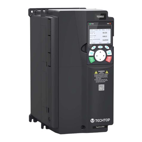
TECHTOP Topdrive350 Series Troubleshooting guide

Topdrive350 Series
Quick Startup Guide
SAFETY PRECAUTIONS
NAMEPLATE IDENTIFICATION
POWER CONNECTIONS
KEYPAD OPERATION
AUTO-TUNING YOUR DRIVE
RESETTING YOUR DRIVE
PARAMETER COPY WITH KEYPAD
CONTROL CONNECTIONS
FREQUENTLY USED PARAMETERS
...............................................01
.................................01
.............................................02
...................................................03
...................................03
...........................................04
.......................04
........................................05
......................07
202006 (V1.0)

Topdrive350 Series
Quick Startup Guide
TECHTOP HIGH-PERFORMANCE VECTOR DRIVES, TD350 QUICK STARTUP GUIDE 1
• Do not refit the inverter unauthorizedly; otherwise fire, electric shock or other injury may occur.
• Please install the inverter on fire-retardant material and keep the inverter away from combustible
materials.
• Connect the braking optional parts according to the wiring diagram.
• Do not operate the inverter if there is any damage or components loss to the inverter.
• Do not touch the inverter with wet items or body, otherwise electric shock may occur.
• Only qualified electricians are allowed to operate/install the inverter.
• Do not carry out any wiring and inspection or changing components when the power supply is
applied. Ensure all input power supply is disconnected before wiring and checking and always wait for
at least the time designated on the inverter or until the DC bus voltage is less than 36V. Below is the
table of the waiting time:
Inverter Module Minimum Waiting Time
3PH 220V 1HP - 75HP 5 Minutes
3PH 460V 2HP - 100HP 5 Minutes
3PH 575V 25HP - 100HP 5 Minutes
This document is intended as a quick start guide to get familiarity with keypad navigation, changing parameters, and setting
the TD350 drive up for external start/stop and external potentiometer signal. Please note this document is not a substitute for
the TD350 User Manual and it is important that you reference the TD350 user manual before proceeding.
SAFETY PRECAUTIONS
NAMEPLATE IDENTIFICATION
45kW/60HP HD 55kW/75HP ND
TD350-045G-4
AC 3PH 380V-480V 94A/128A HD/ND 47Hz-63Hz
AC 3PH 0V-Uinput 92A/115A HD/ND 0Hz-400Hz
Made in China
Techtopcanada.comTechtop Canada Inc.
•
The type designation contains information on the VFD. The
user can find the type designation on the type designation
label attached to the VFD or the simple nameplate.
• Check the inverter nameplate to insure that the information
agrees with your order. Also insure that the power available
is rated appropriately for the drive being used.
Function No. Description Detailed Content
Abbreviation 1Product Abbreviation TD350: Topdrive350 series
Power Range 2Power Range 045G: 45kW, G: Constant torque (HD)
Voltage Degree 3Voltage Degree
2: AC 3PH 200~240V Rated Voltage: 220V
4: AC 3PH 380~480V Rated Voltage: 460V
6: AC 3PH 520~600V Rated Voltage: 575V
TD350-045G-4
1 2 3
NAMEPLATE IDENTIFICATION

Topdrive350 Series
Quick Startup Guide
2
• Always disconnect the main power supply
before touching any electrical component
associated to the inverter. Several
components can remain charged with high
voltages or remain in movement (fans)
even after the AC power is disconnected
or switched off.
• Wait at least five minutes after turning off
the input power for the complete discharge
of the power capacitors.
• Always connect the grounding point of the
inverter to the protection earth (PE).
POWER CONNECTIONS
BEFORE YOU START
Verify the following wiring setup before you turn on the VFD
for the first time:
• Make sure the line voltage (L1/L2/L3) is NOT connected
to the output terminals (U/V/W) of the VFD.
• Ensure the motor is connected to the drive before apply-
ing power to the VFD.
The fuse, braking resistor, input reactor, input filter, out-
put reactor, output filter are optional parts. Please refer to
Peripheral Optional Parts of TD350 user manual for detailed
information.
Remove the yellow warning labels of PB, (+) and (-) on the
terminals before connecting the braking resistor; otherwise,
poor connection may occur.
Terminal 220V ≤20HP
460V ≤40HP
220V≥25HP
460V ≥50HP
575V≥25HP
Function
R, S, T
(L1, L2, L3) Power input of the main circuit
Three phase AC input
terminals which are generally
connected with the power
supply.
U, V, W Power output of the VFD
Three phase AC output
terminals which are generally
connected to the motor.
P1 N/A DC Reactor
Terminal 1
• P1 and (+) are connected
with the terminals of DC
reactor.
• (+) and (–) are connected
with the terminals of brake
unit.
• PB and (+) are connected
with the terminals of brake
resistor.
(+) Brake Resistor
Terminal 1
DC reactor terminal 2,
Brake unit terminal 1
(–) N/A Brake unit
terminal 2
PB Brake Resistor
Terminal 2 N/A
PE
Protective grounding terminals, every machine
is provided 2 PE terminals as the standard
configuration. These terminals should be
grounded with proper techniques.
Protective grounding terminal
Three-phase
Supply
50/60Hz
Input
reactor
Input
filter
Fuse
(+)
(-)
Braking Unit
(optional)
L1
L2
L3
Output
reactor
Output
filter
T3 T2 T1 PE
DC-
DC+
(+)(P1)
DC Reactor
(Optional)
Three-phase
Supply
50/60Hz
Input
reactor
Input
filter
Fuse
(+)
(-)
Braking Unit
(optional)
L1
L2
L3
Output
reactor
Output
filter
T3 T2 T1 PE
DC-
DC+
(+)(P1)
DC Reactor
(Optional)
Three-phase
Supply
50/60Hz
Input
reactor
Input
filter
Fuse
(+)
(-)
Braking Unit
(optional)
L1
L2
L3
Output
reactor
Output
filter
T3 T2 T1 PE
DC-
DC+
(+)(P1)
DC Reactor
(Optional)
Note terminal location will vary depending on VFD rating. This power
connection diagram is based on 220V 18.5–30kW, 460V 37–55kW
and 575V 18.5–37kW TD350 VFDs. For further diagram instructions,
please refer to the TD350 User Manual pages 24-28.
TECHTOP HIGH-PERFORMANCE VECTOR DRIVES, TD350 QUICK STARTUP GUIDE

Topdrive350 Series
Quick Startup Guide
3
Button Button Name Button Description
Confirmation Key
• Function of this key varies with
menus
• Confirm parameter setting/selection
• Entering the next menu, etc.
Function Keys
• Function of these keys varies with
menus
• Function of the these keys will be
displayed in LCD screen footer
Up/Down Left/Right
Keys
• Shifting up/down the display, shifting
digits, switch over monitoring
interface, exit current menu, etc.
• Increase/decrease parameter
settings/values
Quick/Jog Key
• The function of this key is confirmed
by function code P07.02
• P07.02=1, jogging (default)
Run Key • Run the VFD when in local mode,
P00.01=0 (default)
Stop/Reset Key
• Stop the VFD in local mode. Limited
by function code P07.04
• Reset all control modes in the fault
alarm state
*
KEYPAD OPERATION
INITIALIZING YOUR DRIVE
To initialize your drive after power-on, please follow the steps
below.
STEP 1: Select Drive Language
• Select language by using the up/down arrow keys. To
make a selection press any of the following keys:
P02.01 P02.02 P02.03 P02.04 P02.05
Motor kW
1HP=0.746kW
Motor
Frequency Motor RPM Motor Voltage Motor Amps
0.1 to 3000kW 0.01Hz to
P00.03
1 to 36000
r/min 0 to 1200V 0.8 to
6000.0A
TECHTOP HIGH-PERFORMANCE VECTOR DRIVES, TD350 QUICK STARTUP GUIDE
01: TD350
16:02:35 Forward Local Ready
Set frequency
P17.00 Hz
DC bus voltage
P17.11 V
AboutMonitoring Menu
Digital input terminal state
P17.12
A B C
DE
F
60.00
648.0
0x0000
LCD Display Name Display Contents
AReal-time display • Display real time of VFD
BVFD running state • Display current state of VFD
CVFD station number • Display the VFD station from 01-99
DParameter name • Display Parameter name and code
EParameter value • Parameter value monitored by VFD
FFunction key menu • Display of function key menu
• After language selection, you can choose to re-select the
language during each power-on or just once.
STEP 2: Enter the Init (initialize) Setting
• Press any of the following keys to enter init setting:
STEP 3: Basic Parameter Settings
• The initialize will guide you through 14 basic parameter set-
tings. For details on each parameter see the User Manual.
Parameter Name Selections Default
P00.06 A freq cmd 0-15 0: keypad
P00.01 Run cmd channel 0-2 0: keypad
P00.02 Comm cmd channel 0-5 0: MODBUS
P08.37 DynBraking Enable 0-1 1: enabled
P00.00 Speed Ctrl 0-3 2: SVPWM
P01.08 Stop Mode 0-1 1: Dec to stop
P00.11 Acc time1 0.0 to 3600.0s Depends on model
P00.12 Dec time1 0.0 to 3600.0s Depends on model
P02.00 Motor1 Type 0-1 0: Asynchronous
• Enter the motor nameplate data in the next set of
parameters:

• Perform the motor auto-tune by pressing the key.
• Once auto-tune is complete, select confirm.
• Speed control mode can be set using function code P00.00
(see step 3).
RESETTING YOUR DRIVE
To reset your drive to factory default settings, follow the instructions
below.
• From the Homepage select Menu by pressing function button
• Using the Up/Down keys, scroll down to find Parameter copy/
restore to default. Follow the screens below:
INITIALIZING YOUR DRIVE CONTINUED
STEP 5 Continued
• Select one of the three Auto-Tuning options:
**Type Description
Complete Rotary Auto-Tuning*
(P 0 0.15=1)
Comprehensive motor parameter auto-tuning. It is
recommended to use this setting when high control
accuracy is needed
Complete Static Auto-Tuning 1
(P 0 0.15=2)
Suitable in cases where the motor cannot be decoupled
from the load
Partial Static Auto-Tuning 2
(P 0 0.15= 3)
Suitable in cases where the motor cannot be decoupled
from the load. Only auto-tunes for P02.06, P02.07
and P02.08
*Recommended setting for auto-tuning. Must be preformed with motor decouple and discon-
nected from load.
Topdrive350 Series
Quick Startup Guide
4
PARAMETER COPY WITH KEYPAD
Drive parameters can be copied and stored using the TD350 LCD keypad.
• From the Homepage select Menu by pressing function button
• Using the Up/Down keys, scroll down to find Parameter copy/re-
store to default. Follow the screens below:
TECHTOP HIGH-PERFORMANCE VECTOR DRIVES, TD350 QUICK STARTUP GUIDE
STEP 5: Conduct Self Learning (Auto-Tuning)
• Perform motor parameter auto-tuning by selecting
Yes when prompted. Make sure that the motor name-
plate information has been entered correctly in Step
3. Note, Autotuning is only necessary when P00.00 =
0, 1 or 3. When P00.00 = 2 (SVPWM) this step is not
required.
STEP 4: Confirm Rotational Direction
• Test the motor rotating direction by selecting Yes
• Press the key and confirm if the direction is
consistent with expectations. If No is selected the
drive will change the direction by auto setting param-
eter P00.13=1 and the LCD header will display Rev.
01: TD350
16:02:35 Forward Local Ready
Return Homepage Select
Parameter setup
User defined parameter setting
State parameter/fault record
Motor parameter autotuning
Parameter copy/Restore default
System setting
01: TD350
16:02:35 Forward Local Ready
Return Homepage Select
memory area 1: BACKUP01
memory area 2: BACKUP02
memory area 3: BACKUP03
Restore func prm to default
01: TD350
16:02:35 Forward Local Ready
Return Homepage Confirm
Confirm restore function prm
to default value?
1 2 3
01: TD350
16:02:35 Forward Local Ready
Return Homepage Select
Parameter setup
User defined parameter setting
State parameter/fault record
Motor parameter autotuning
Parameter copy/Restore default
System setting
01: TD350
16:02:35 Forward Local Ready
Return Homepage Select
memory area 1: BACKUP01
memory area 2: BACKUP02
memory area 3: BACKUP03
Restore func prm to default
01: TD350
16:02:35 Forward Local Ready
Return Homepage Select
UL local func prm to keypad
DL complete func prm of keypad
DL non-motor group func prm of keypad
DL motor group func prm of keypad
1 2 3
1.
2.
3.
4.
1. Upload the drive parameters to the keypad memory area
2. Download ALL keypad stored parameters to the drive
3. Download ALL keypad parameters excluding group P02
4. Download keypad stored parameters for ONLY group P02
3
**To quickly access the Auto-Tune function from the homepage, select: Menu > Motor
parameter autotuning

Topdrive350 Series
Quick Startup Guide
5
CONTROL CONNECTIONS
Multi-function input terminal 1
S4
S3
S2
S1
Multi-function input terminal 2
Multi-function input terminal 3
Multi-function input terminal 4
HDIA
High-speed pulse input or
Open collector input
HDIB
High-speed pulse input or
Open collector input
COM
PW
+24V
PE
+10V Power used for
frequency setting
AI1 Multi-function
analog input
AI2
GND
PE
Safety
Input
Safety
swith
-10V
(external)
H1
H2
S1
S2
Open circuit
Safety
controller
+24V
Safety state
feedback
SW2 AO1
GNDV I
Analog output
0-10V/0-20mA
Optional between high-
speed pulse output and
open collector output
Y1
CME
Y1
Output
HDO
COM
RS485
communication
SW3
ON OFF
485+
485-
485G
Relay 1
output
Relay 2
output
RO1A
RO1B
RO1C
RO2A
RO2B
RO2C
REMOTE 2-WIRE START/STOP SETUP, WITH
SPEED POTENTIOMETER
Default Setting: The TD350 by default uses the keypad com-
mand to run and stop, follow instructions below to change to a
remote 2-wire start/stop with 0-10V speed reference.
Instructions to change to remote run/stop:
• Power down the drive, wait 5 min.
• Remove the protective covers (See TD350 User Manual) and
make the connections as shown below (see step 2).
• Verify that all connections are secure, replace covers
and power-up the drive.
• Follow the parameter settings in right hand table (see steps
3-5).
S1 S2 S3 S4 HDIA AI1 AI2 +10V
COM Y1 AO1 GND
HDIB
H2 +24V COM 485+PE 485-
H1 +24V +24V PW HDO
CME 485G
COM
Potentiometer
SPEED CONTROL
Switch
START/STOP
Jumper Jumper
*Parameter Default Change To
P00.01 0: Keypad (local) running
command channel
1: Terminal running
command channel
P00.06 0: Keypad, A frequency
command
1: AI1, A frequency
command
P05.01 1: S1 set to forward
rotation operation --
01: TD350
16:02:35 Forward Trml Ready
Set frequency
P17.00 Hz
DC bus voltage
P17.11 V
AboutMonitoring Menu
Digital input terminal state
P17.12
60.00
648.0
0x0000
When P00.01=1
Local indicator will
change to Trml for
remote operation.
3
4
5
3
*To quickly access the function codes from the homepage, select:
Menu > Parameter setting > Func code quick setting
1
2
Terminals Quantity Description
Digital input 4 (S1-S4) 1kHz, NPN and PNP
(default NPN)
High speed
pulse input 2 (HDIA-HDIB) 50kHz, NPN and PNP
(default NPN)
Analog input 2 (AI1-AI2) 0~10V, 0~20mA,
-10V~+10V
ON-OFF output 1 (Y1) Maximum output
frequency: 1kHz
High speed
pulse output 1 (HDO) Maximum output
frequency: 50kHz
Analog output 1 (AO1) 0~10V, 0~20mA
Relay output 2 (RO1-RO2) 3A/250VAC,
1A/30VDC, NO+NC
Safe Torque Off
(STO) 2 (H1-H2) Integrates safety
function-STO, SIL2
TECHTOP HIGH-PERFORMANCE VECTOR DRIVES, TD350 QUICK STARTUP GUIDE

REMOTE 3-WIRE START/STOP SETUP, WITH
4-20mA REFERENCE
Default Setting: The TD350 by default uses the keypad com-
mand to run and stop, follow instructions below to change to a
remote 3-wire start/stop with 4-20mA speed reference.
Instructions to change to remote run/stop:
• Power down the drive, wait 5 min.
• Remove the protective covers (See TD350 User Manual) and
make the connections as shown below (see step 2).
• Verify that all connections are secure, replace covers
and power-up the drive.
• Follow the parameter settings in right hand table (see steps
3-9).
When P00.01=1
Local indicator will
change to Trml for
remote operation.
3
*Parameter Default Change To
P00.01 0: Keypad running
command channel
1: Terminal running command
channel
P00.06 0: Keypad, A frequency
command 1: AI1, A frequency command
P05.50 0: Voltage type 1: Current type
P05.01 1: S1 set to forward
rotation operation --
P05.02 4: S2 set to forward
Jogging
3: S2 set to 3-wire control
operation
P05.03 7: S3 set to fault reset 2: S3 set to reverse rotation
operation
P05.11 0: 2-wire contol 1 2: 3-wire contol 1
3
4
5
6
7
8
9
CONNECTING A 24VDC PILOT LIGHT TO OUTPUT
RELAYS
Default Setting: The TD350 by default switches RO1 relay
contact when drive is in the run operation command. A terminal
is normally open, B is normally closed and C is common.
Instructions to change to remote run/stop:
• Power down the drive, wait 5 min.
• Remove the protective covers (See TD350 User Manual) and
make the connections as shown (see step 2).
• Verify that all connections are secure, replace covers
and power-up the drive.
• Follow the parameter settings in right hand table (see step
3).
RO1A RO1B RO1C
RO2A RO2B RO2C
24VDC Pilot Light
START/STOP INDICATOR
S1 S2 S3 S4 HDIA AI1 AI2 +10V
COM Y1 AO1 GND
HDIB
H2 +24V COM 485+PE 485-
H1 +24V +24V PW HDO
CME 485G
COM
Jumper Jumper
*Parameter Default Change To
P06.03 1: In operation --
3
1
2
1
2
Topdrive350 Series
Quick Startup Guide
6
S1 S2 S3 S4 HDIA AI1 AI2 +10V
COM Y1 AO1 GND
HDIB
H2 +24V COM 485+PE 485-
H1 +24V +24V PW HDO
CME 485G
COM
Jumper Jumper
N.O. SB1
START
N.C. SB2
STOP
Switch
REVERSE
4 to 20 mA
Reference
+
_
TECHTOP HIGH-PERFORMANCE VECTOR DRIVES, TD350 QUICK STARTUP GUIDE
01: TD350
16:02:35 Forward Trml Ready
Set frequency
P17.00 Hz
DC bus voltage
P17.11 V
AboutMonitoring Menu
Digital input terminal state
P17.12
60.00
648.0
0x0000
*To quickly access the function codes from the homepage, select:
Menu > Parameter setting > Func code quick setting
*To quickly access the function codes from the homepage, select:
Menu > Parameter setting > Func code quick setting

Topdrive350 Series
Quick Startup Guide
7
FREQUENTLY USED PARAMETERS
Function Code Name Description Default Value
P00.00 Speed Control Mode
0: SVC 0 - Sensorless Vector Control mode 0. Suitable for
applications which need low power.
1: SVC 1 - Sensorless Vector Control mode 1. Suitable in high
performance cases with the advantage of high accuracy of rotating
speed and torque.
2: SVPWM Control - V/Hz control. Suitable in applications that
do not require high control accuracy, such as the load of a fan or
pump. One inverter can drive multiple motors.
Note: Carry out motor parameter auto-tuning before selecting SVC
0, SVC 1 or VC
3: VC - Vector Control mode.
2
P00.01 Run Command Channel
0: Keypad running command channel (LOCAL)
1: Terminal running command channel (REMOTE)
2: Communication running command channel
0
P00.03 Max Output Frequency Setting range: P00.04 to 400.00Hz 60.00Hz
P00.04 Upper Limit of The Running
Frequency Setting range: P00.05 to P00.03 60.00Hz
P00.05 Lower Limit of The Running
Frequency Setting range: 0.00Hz to P00.04 0.00Hz
P00.11 ACC Time 1 (Acceleration) Setting range: 0.0 to 3600.0s Depends on model
P00.12 DEC Time 1 (Deceleration) Setting range: 0.0 to 3600.0s Depends on model
P00.13 Running Direction Selection
0: Runs at default direction, the inverter runs in the forward
direction. FWD/REV indicator is off.
1: Runs in the opposite direction, the inverter runs in the reverse
direction. FWD/REV indicator is on.
2: Forbid to run in reverse direction: it can be used in some special
cases if the reverse running is disabled.
0
P00.14 Carrier Freqency Setting Setting range: 1.0 to 15.0kHz Depends on model
P00.15 Motor Parameter Auto-Tuning
0: No operation
1: Rotating Auto-Tuning (dynamic). Motor must be de-coupled from
load.
2: Static Auto-Tuning 1
3: Static Auto-Tuning 2. Auto-tune for P02.06, P02.07, P02.08
0
P00.18 Function Restore Parameter
0: No operation
1: Restore to default value
2: Clear fault history
0
P01.05 ACC/DEC Selection
0: Linear type. The output frequency increase/decreases linearly.
1: S curve. The output frequency will increase or decrease according
to the S curve.
0
P01.06 ACC time of the starting step of
S curve Setting range: 0.0 to 50.0s 0.1s
P01.07 DEC time of the starting step of
S curve Setting range: 0.0 to 50.0s 0.1s
P 0 7.0 0 User Password
0 to 65535: the password protection will be valid when setting any
non-zero number
00000: Clear the previous user’s password and make password
invalid
0
P 0 7.0 2 QUICK/JOG Key Function
Selection
0: Null
1: Jogging
2: Reserved
3: Switch between FWD/REV rotation
4:Clear UP/DOWN setting
5: Coast to stop
6: Swith over to the running command reference in sequence
1
TECHTOP HIGH-PERFORMANCE VECTOR DRIVES, TD350 QUICK STARTUP GUIDE

Techtop Canada Inc. Copyright.
Information may be subject to change without notice during product improvements.
Other manuals for Topdrive350 Series
1
This manual suits for next models
1
Table of contents
Other TECHTOP DC Drive manuals

