US Cutter Copam User manual


- 1 -
Contents
Welcome ........................................................................................................................................................................... 3
Cutter Parts ...................................................................................................................................................................... 4
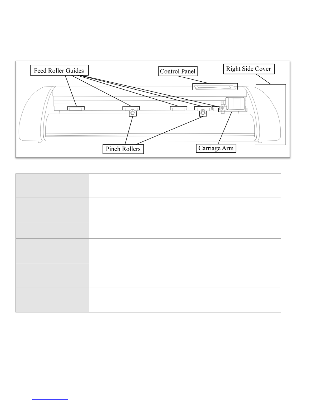
Front View ...................................................................................................................................................................... 4
Detail of Carriage Arm ................................................................................................................................................. 5
Right Side View .............................................................................................................................................................. 5
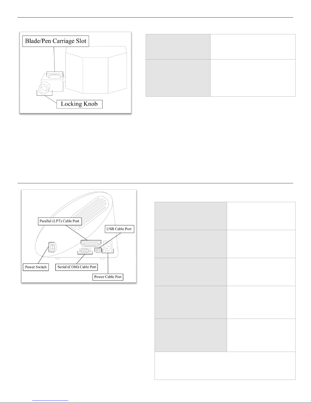
Back View ........................................................................................................................................................................ 6
Detail of Pinch Roller ................................................................................................................................................... 6
Control Panel .................................................................................................................................................................. 7
Measure Screen .............................................................................................................................................................. 7
Paper Size Screen ............................................................................................................................................................ 7
Function Select Screen .................................................................................................................................................. 8
Setup Screen .................................................................................................................................................................... 9
Jog Screen ...................................................................................................................................................................... 10
Pause Screen .................................................................................................................................................................. 11
Setting up ....................................................................................................................................................................... 12
Selecting a Location for the Cutter .......................................................................................................................... 12
Connecting the Cutter to a Computer .................................................................................................................... 12
Installing SignBlazer Software ................................................................................................................................... 14
Installing SignCut Software ........................................................................................................................................ 15
Installing a New Blade ................................................................................................................................................. 16
Replacing a Worn Blade ............................................................................................................................................. 17
Installing a Pen Carriage ............................................................................................................................................. 18
Preparing for Cutting .................................................................................................................................................. 20
Step By Step Instructions ....................................................................................................................................... 25
Starting SignBlazer for the First Time ...................................................................................................................... 25
Making a Simple Cut in SignBlazer .......................................................................................................................... 27
Importing in SignBlazer .............................................................................................................................................. 29
Converting a Raster Image to Vector Image in SignBlazer.................................................................................. 32
Starting SignCut and Inkscape for the First Time ................................................................................................. 35
Creating a Simple Design in Inkscape....................................................................................................................... 37

- 2 -
Cutting a Simple Design in SignCut ......................................................................................................................... 41
Converting a Raster Image to Vector Image in Inkscape .................................................................................... 43
Specifications ............................................................................................................................................................... 47
Troubleshooting ......................................................................................................................................................... 48

- 3 -
Welcome
Thank you for choosing a Copam cutter from US Cutter. The Copam cutters provide a
professional level, high quality cutting experience for a fraction of the cost of most cutters of this
quality. This manual is here to help provide a starting point in the learning process of the Copam
cutters or to vinyl cutting in general. Please read it thoroughly and follow the steps carefully to help
insure a trouble free experience with your new machine. If you have any questions along the way,
we have provided a few locations to go to get those questions answered. You can post on the US
Cutter forums at forum.uscutter.com, submit a request for support on the support website at
support.uscutter.com, or call customer service at 425-481-3555. We hope you enjoy your experience
with your new cutter and the US Cutter family.

- 4 -
Cutter Parts
Before you start cutting, you should familiarize yourself with the cutter and its basic parts and functions:
Front View
Control Panel
Used to provide input directly to the cutter. Covered in detail in the
“Control Panel” (page 7) section of this manual.
Carriage Arm
Holds the Blade (or Pen) Carriage. Shown in detail on page 5.
Pinch Rollers
Holds the media tightly to the feed roller below. Shown in detail on page
6.
Feed Roller Guides
Shows the location of each feed roller so that the pinch rollers can be
properly positioned to make contact with the feed rollers.
Feed Rollers
(Not Pictured. Located below
each Feed Roller Guide.)
Positions the cutting material during operation.
Right Side Cover
Contains the Power Switch and the Parallel, Serial, USB and Power
cable ports for the cutter. Shown in detail on page 5.

- 5 -
Detail of Carriage Arm
Right Side View
Blade/Pen Carriage
Slot
Holds the Blade or Pen
Carriage in place.
Locking Knob
Allows access to the
Blade/Pen Carriage Slots for
exchanging/replacing
Carriages.
Parallel Cable Port*
Used to connect a
parallel cable from the
cutter to a computer.
Serial (COM) Cable
Port*
Used to connect a serial
cable from the cutter to
a computer.
USB Cable Port*
Used to connect a USB
cable from the cutter to
a computer.
Power Cable Port
Used to connect a
power cable from the
cutter to a wall outlet
or surge protector.
Power Switch
Main power switch for
turning the power of
the cutter on(1) or
off(0).
*Only one of the connection cables should be used to
connect the cutter to a computer.

- 6 -
Back View
Pinch Rollers
Holds the media tightly to the feed roller below. Back view shown in detail below.
Detail of Pinch Roller (Back View)
Tension Screw
Adjusts the tension of how tightly
the pinch roller is held to the feed
roller below.
Release Lever
Allows you to release Pinch Rollers
(either so they can be moved from side
to side or to allow media to be easily fed
below them) by pulling up on the
Release Levers.

- 7 -
Control Panel
Measure Screen
The Measure Screen is the first screen that you will see when starting up the cutter. Select your media
type from the menu and then confirm your selection. The cutter will then measure your material and
report the cuttable area (in millimeters) on the Paper Size Screen (Next). If „Scroll‟is selected, only the width is
measured. If „Sheet‟is selected than both the width and length of the material will be measured.
Paper Size Screen
The Paper Size Screen will display after a measurement has been made from the Measure Screen. This will
display the cuttable area that the machine has detected for your media (in millimeters). You can record the
dimensions and use them as a reference on your cutting software to ensure that you are creating designs
that will fit within the cuttable area of your material.
Left/Right
Buttons
Selects between the „Scroll‟ and „Sheet‟ media types. If you are cutting from a single sheet
of media, select „Sheet‟. If you are cutting from a roll of media, select „Scroll‟.
Enter Button
Confirms the selection between „Scroll‟ and „Sheet‟.
All other buttons have no function on this screen.
Enter Button
Exits the Paper Size screen and continues to the Function Select Screen (Next).
All other buttons have no function on this screen.

- 8 -
Function Select Screen
The Function Select Screen is the main screen for the cutter. From this screen you can access the Measure
and Setup Screens, make test cuts, make a repeat cut of the last cut made by the cutter, or adjust the origin
of the of the next cut to be made.
Measure
Button
Accesses the Measure Screen (page 7) where the material loaded in the cutter can be
measured and the size of the cuttable area can be displayed.
Test Button
Cuts a small test pattern to demonstrate the current settings of the cutter and allow you
to see if they are appropriate for your current material. After the test cut has been
made, the cutter will display the Setup Screen (page 9) to allow the option of changing
any settings.
Setup Button
Accesses the Setup Screen (page 9)where the main settings of the cutter can be
viewed/changed.
Pause Button
Has no function on this screen.
Enter Button
Has no function on this screen when used alone. Can be used with the right and left arrow
keys to perform advanced functions (below).
Enter Button
+
Left Arrow
Button
When the Enter Button is pressed simultaneously with the Left Arrow Button a detailed
test cut is made. This detailed test cut can be used to test the current settings of the
cutter when the small test pattern is not sufficient for testing and also for more advanced
troubleshooting.
Enter Button
+
Right Arrow
Button
When the Enter Button is pressed simultaneously with the Right Arrow Button a repeat
cut is made of the last cut that was sent to the cutter. This is a simple way to make
duplicate cuts of the same design. The repeat cut function will only retain the last cut
information until the cutter is powered off. When the cutter is powered off, the last cut information
is removed from the cutter memory and the repeat cut function will not be available until a new cut
has been made.
Up/Down/
Left/Right
Arrow
Buttons
Pressing any of the arrow buttons will access the Jog screen of the cutter (Page 10)
where a new starting position can be entered for the next cut.

- 9 -
Setup Screen
The Setup screen allows you to view/adjust the main settings for the cutter. You can adjust the speed at
which the cutter moves while cutting, the amount of force used to make cuts, and the blade offset which
compensates for slight variations in blade sizes. You can also make a test cut to see if any of the settings
need to be changed, or to check if the changes you are making are improving cutter performance.
Speed Setting: The Speed Setting will adjust the rate at which the cutter operates while cutting. On
smaller or more detailed designs, the speed should lowered to increase the precision of the machine. On
larger or less detailed designs, the speed can be raised to decrease cut time.
Force Setting: The Force Setting will adjust the amount of pressure that the blade uses when cuts are
being made by the machine. This setting should be used in conjunction with proper blade depth (page 16)
to allow the blade to fully cut the material, but not cut through the protective backing material of your
selected media. Your blade depth should be adjusted to approximately;
The height of your cuttable material + ½ of the height of the backing material.
This will allow the blade to fully cut the material without fully penetrating the backing. Once you have
blade depth properly adjusted, change the pressure setting until you are getting smooth cuts.
Offset: The Offset Setting allows the cutter to adjust for slight variations in different blade sizes. If your
cuts are not fully closing, or are overlapping, you can adjust the Offset Setting to correct it. Standards for
blade offsets are often found on the packaging of, or in the instructions that come with, the blade.
Left/Right
Arrow Buttons
Selects the setting to be changed.
Up/Down
Arrow Buttons
Adjusts the parameters of the selected setting.
Enter Button
Accepts the changes made and returns to the Function Select Screen. If you accessed the
Setup screen from the Pause Screen, the Enter button will return to the Pause Screen.
Test Button
Cuts a small test pattern to demonstrate the current settings of the cutter and allows
you to see if they are appropriate for your current material. After the test cut has been
made, the cutter will return to the Setup Screen and further changes can be made. If
you cut a test shape after entering the Setup Screen from the Pause Screen, the current cut will be
canceled before the test cut is made.
All other buttons have no function on this screen.

- 10 -
Jog Screen
The Jog Screen is where the cutter, and the material loaded in the cutter, can be moved to create a new
starting location for the next cut to take place from. The X and Y values on this screen will show the
amount of movement that has taken place in relation to the initial origin of the cutter. You will only be able
to move the cutter within the cuttable area that has been determined when the material was measured by the cutter.
Left/Right
Arrow Buttons
Moves the Carriage Arm from side to side.
Up/Down
Arrow Buttons
Moves the material forwards and backwards.
Enter Button
(pressed)
Pressing the Enter Button will return to the Function Select Screen but will not reset
the origin of the cutter or material. To reset the origin you must hold the Enter Button for 2
seconds (below).
Enter Button
(held down)
Holding the Enter Button for 2 seconds will reset the origin of the cutter. The next
cut that takes place will be made from this new origin location.
All other buttons have no function on this screen.

- 11 -
Pause Screen
The Pause Screen is accessed by pressing the pause button while to cutter is cutting. From the Pause
Screen you can enter the Setup Screen to change the main settings of the cutter, cancel the current cut, or
exit the pause screen and continue cutting. You can also move the loaded material forwards or backwards, though
doing so after a cut has begun is not recommended.
Setup: Enters the Setup Screen (page 9). Allows to you to change the cutters main settings. If a test cut is
made from the Setup Screen the current cut will be canceled.
Abort: Cancels the current cut and returns to the Function Select Screen (Page 8). When you cancel a cut
from the cutter, you should also be sure to cancel the cut from the cutting software on your computer.
Pause Button
Exits the Pause Screen and resumes the current cut.
Left/Right
Arrow Buttons
Selects between the „Setup‟ and „Abort‟ options.
Enter Button
Confirms the selection between „Setup‟ and „Abort‟
Up/Down
Arrow Buttons
Moves the loaded media forwards and backwards similar to the Up/Down arrow buttons
on the Jog Screen (page 10). Moving the material after a cut has started is not recommended.

- 12 -
Setting up
If you are setting up for the first time please take a moment to refer to the Packaging Guide to take account off all the
included components and accessories.
For help with Stand Assembly, please refer to the included instructions.
Selecting a Location for the Cutter
The first step to setting up your cutter is finding a good location for the machine. Consider these factors
when you are selecting a suitable place:
You will need to have access to both the front and rear of the machine for operations as well as for
loading and unloading new vinyl rolls. Try to find a space with adequate access to both the front
and back of the machine.
Since your cutter is a precision cutting device, you will want to find a location that will be stable to
insure cutting accuracy. Whether placing the unit on the stand, a floor or a table top, the accuracy
of the machine will be directly related to the stability of the platform it is placed on. Find a sturdy
floor space or table top for the machine and consider a location that will be out of the way of
people and other machines with moving parts while the cutter will be operating. Excessive moving
of the machine can not only disrupt accuracy of cutting but may also cause electrical components
inside the machine to dislodge and require otherwise unnecessary repairs and maintenance.
Fans located inside of the cutter can draw in outside dust from the area surrounding the cutter.
Excessive buildup of dust can cause either mechanical or electronic malfunctions. Keeping the
cutter as dust free as possible will help ensure trouble free operation. Try to find an area for the
cutter that will be free of any excessive dust and use the supplied cover when not in use.
All cutters will produce a small amount of noise while operating. Please take this into consideration
when selecting a location for your cutting purposes.
Do not remove the grounding plug from the power cord or attempt to use the cutter when it has
not been properly grounded.
Use all available wheel brakes on the cutter stand to reduce movement during cutting.
Keep the cutter away from liquids, heat sources and strong magnets.
Connecting the Cutter to a Computer
Attach the power cord to the cutter and then plug in the unit and turn on the power.
If Using the a Serial or Parallel Cable to connect your cutter to a Computer:

- 13 -
If you are using a Serial or Parallel Cable to connect your cutter to a computer then no further setup is
necessary. Simply connect one end of the cable to the cutter and the other end to a computer and setup is
complete. If you have more than one serial/parallel connection on your computer or you are experiencing
communication issues between your cutter and computer then you may wish to verify that the correct port is being used
in your software setup (see Finding Your COM/LPT Port on the next page), but for most users the port will be 1(i.e.
COM1/LPT1).
If Using the USB Cable to connect your cutter to a Computer:
You will need to install drivers for the USB connection to work properly. These drivers can either be
obtained from the supplied drivers disc or downloaded from the support website (in the downloads section of
support.uscutter.com).Mac Users will need to download drivers from the support website as the drivers included on the
disc are Windows only.
Windows XP Users:
1. Insert the driver disc or download (and unzip if necessary) drivers to your system.
2. Connect the USB Cable to your computer and your cutter. The Found New Hardware wizard will
appear.
3. When asked, “Can Windows connect to Windows Update to search for software?” select “No, not
this time” and click next.
4. When asked, “What do you want the wizard to do?” select “Install from a list or specific location
(Advanced)” and click next.
5. Choose the “Search for the best driver in these locations” radio button and check the “Include this
location in the search” checkbox. Now type (or browse to find) the location of the downloaded
drivers/inserted drivers disc and click next.
6. When the wizard is complete, click the Finish button.
7. The Found New Hardware wizard should appear again. When it does, follow steps 3-6 again for
the second driver.
Windows Vista Users:
If you want to use downloaded drivers, download them before starting the install process.
1. Connect the USB Cable to your computer and your cutter. The Found New Hardware wizard will
appear.
2. When told that “Windows needs to install driver software…” select “Locate and install driver
software (recommended)”.
3. If Windows finds and downloads your needed drivers then the process is complete. Repeat the
previous steps again for the second needed driver. If Windows does not find and download the
needed drivers proceed to the next step.
4. If you are going to install the drivers from the disc insert it when advised by Windows. If you are
going to use downloaded drivers, select “I don‟t have the disc. Show me other options.”
5. Browse to the folder where the drivers are stored and click next.
6. When the wizard is complete, click the close button.
7. The Found New Hardware wizard should appear again. When it does, follow steps 2-6 again for
the second driver.
If you are using another version of Windows or a Mac OS and require specific instructions for installing the drivers, they
can be found at: ftdichip.com/Documents/InstallGuides.htm.

- 14 -
Once your drivers are installed you will need to make a note of the COM port that has been assigned to
your USB Cable connection.
-Finding Your COM/LPT Port
First navigate to the Device Manager by following the below instructions for your operating
system:
Windows 95/98/Me Users:
Click Start, then select Settings -> Control Panel.
Select Device Manager.
Windows 2000/XP Users:
Click Start, Then Right-click “My Computer”then select Properties.
Select the Hardware tab.
Click the Device Manager button.
Windows Vista/7 Users:
Click Start, Then in the "Start Search" box, Type "Dev" (without pressing enter); wait for a
list to show up.
Click Device Manager.
Expand the section labeled “Ports (COM & LPT)”.
Make a note of which number COM/LPT Port is associated with your cutter.
You will need this information to properly install your software.
Installing SignBlazer Software
Insert the SignBlazer Elements CD into your computer.
Select “Run Setup” .
Follow the on screen instructions.
Ignore the warning of only being able to install SignBlazer on one computer. This does not apply since you
will be using trial mode and updates are no longer available for the SignBlazer software.
When asked what cutter you want to use, select the model that matches your Copam cutter (2500, 4050
or 4500).
When asked if you want to install the USB driver, select “No” since we have already done so.

- 15 -
When asked what port your cutter uses, select the Port that corresponds with your setup. If using a USB
connection you will need to select the COM port that corresponds with your setup (Noted above from the
“Finding Your COM Port” section of the manual).
Make sure that your Baud Rate option is set to 9600.
Do not change the, Data Bits, Stop Bits, or Parity options.
Make sure the Flow Control option is set to “Hardware”.
Installing SignCut (and Inkscape*) Software
*If you will be using the SignCut software to cut from your computer you will also need a vector design program.
SignCut is strictly a cutter interface and cannot be used to create signs and designs. The instructions in this manual will
give directions for using Inkscape (A popular free vector design program) with SignCut but directions for other software
will be mostly the same. If you prefer creating vector graphics in Illustrator, CorelDraw, or another vector graphic
design program then you can choose to not install Inkscape and work with your preferred software.
Go to: www.signcutpro.com/bundle.html
Fill out the form and click “Register”
You will be directed to a page where you will be given a download link and a license number. Save this
page or print it for reference. A copy of this page will also be sent to the email address used while filling
out the Registration form.
Follow the link to the web address that corresponds to your operating system and download the SignCut
software installation program.
After the SignCut software installation program has been downloaded, run the program and follow the on
screen instructions.
You will be asked if you would also like to download Inkscape. If you have not already done so and you
would like to use the Inkscape software as a vector design program, select the yes button and the Inkscape
software will be downloaded.
Follow the Inkscape installation instructions. SignCut installation will be temporarily paused.
When you are finished installing Inkscape SignCut will resume installation and finish.
Installation is now complete.

- 16 -
Installing a New Blade
Unscrew the
cap from the
Blade
carriage.
Set Brass Ring
on Blade
Carriage to the
fully down
position
Remove the
protective
cover from
a new
blade.
Insert the
blade into
the top of
the Blade
carriage.
Screw the
cap back
onto the
blade
carriage.
Adjust the
carriage cap
until the blade
is protruding
approximately
1/64th of an
inch.*
Adjust the
Brass Ring
until it fits
snug against
the Cap. This
will help keep
the cap in
place during
operation.
*This distance will vary depending on what material you are cutting. Your blade depth should be adjusted
to approximately;
The height of your cuttable material + ½ of the height of the backing material.
This will allow the blade to fully cut the material without fully penetrating the backing. 1/64th of an inch is
a general guide that will work well with many common vinyl products and is a good starting point for determining the
blade depth for your material, but some adjustments/fine tuning to blade depth will be necessary in most cases.

- 17 -
Replacing a Worn Blade
First remove the blade carriage from the carriage arm,
Unscrew the cap of
the blade carriage
Carefully pinch the
blade on both sides
and pull it up and out
of the Blade
Carriage.
Follow the steps from “Installing a New Blade” on the previous page.
Loosen the locking knob on the
carriage arm.
Place Blade carriage into the
carriage arm.
Tighten the locking knob on the
carriage arm.

- 18 -
Installing a Pen Carriage (Optional)
Many new users will benefit from practice “cutting” with the optional pen carriage until they are comfortable with
normal operations of the cutter and cutting software.
Your Pen Carriage should come assembled and appear as it does in this image. If it does not, please refer to the pen
replacement section below for assembly instructions.
To install the pen carriage:
To Replace the pen or spring inside of the Pen Carriage:
Unscrew the top cap from the Pen carriage.
Loosen the locking knob on
the carriage arm.
Drop the pen attachment into
place in the front slot of the
carriage arm.
Tighten the locking knob on
the carriage arm.

- 19 -
Remove the top cap, the pen and the spring. Replace the pen and/or spring as necessary. Slide the spring
onto the pen from the top and insert it back into the pen carriage.
Replace the carriage cap and screw into place.
Once you are familiar with the cutter and its basic functions, install the blade carriage (next).
Table of contents
Other US Cutter Cutter manuals

US Cutter
US Cutter Laserpoint II User manual

US Cutter
US Cutter MH-721 User manual

US Cutter
US Cutter SC2 User manual

US Cutter
US Cutter Titan User manual

US Cutter
US Cutter LaserPoint User manual

US Cutter
US Cutter LaserPoint3 User manual

US Cutter
US Cutter MH Series User manual

US Cutter
US Cutter SC User manual
Popular Cutter manuals by other brands

RotaTrim
RotaTrim Mastercut Monorail MC Series instruction manual

ACCO Brands
ACCO Brands EBA 436 E specification

CLEAN ROOM DEVICES
CLEAN ROOM DEVICES CRD130 Operation manual

REMS
REMS Cento instruction manual

HOLZMANN MASCHINEN
HOLZMANN MASCHINEN K5 315VF-2000 user manual

ATIKA
ATIKA ST 250 Operating manual – safety instructions – spare parts