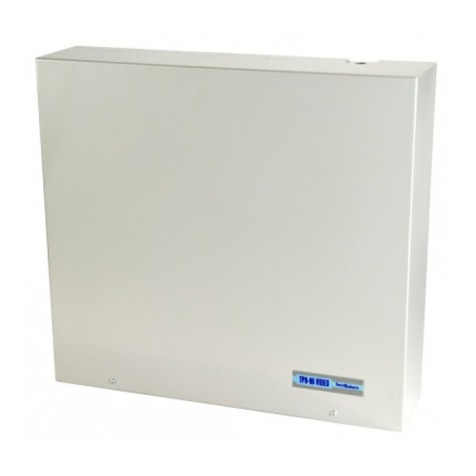
Tecnoalarm TP16-256 User guide

INSTINST
INSTINST
INSTALLERALLER
ALLERALLER
ALLER
MANUMANU
MANUMANU
MANUALAL
ALAL
AL
Release: 1.0
Update: April 2009
Language: English
FW version: 2.4
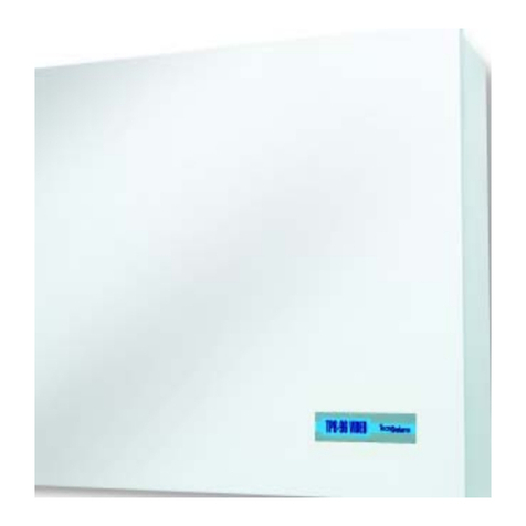
TP16-256
16 TO 256 ZONES
EXPANDIBLE CONTROL
PANEL
EN 60950
EN 50130-4
EN 50081-1

II Installer Manual - TP16-256
The features of the control panel can be subject to change without notice.
Unauthorized reproduction or distribution of this manual, or any portion of it, on any device and in any form, is
prohibited.
The contents of this manual may be subject to change without notice.

III
TP16-256 - Installer Manual
CONFORMITY
Hereby, Tecnoalarm srl declares that the present equipment is in compliance with the essential requirements
and other relevant provisions of the R&TTE 1999/05/EC directive.
The declaration of conformity is available on the website: www.tecnoalarm.com.

IV Installer Manual - TP16-256

TP16-256 - Installer Manual Index 1
INDEX
1. GENERAL FEATURES
1.1 HARDWARE 1-1
1.2 MAIN FUNCTIONS 1-2
2. HARDWARE
2.1 CONTROL PANEL 2-1
2.2 CONNECTION 2-3
2.2.1 Wall mounting 2-3
2.2.2 Mains connection 2-4
2.3 BATTERY CONNECTION 2-6
2.4 CPU BOARD 2-7
2.4.1 Serial ports 2-8
2.4.2 Telephone section 2-9
2.4.3 Terminal board 2-10
2.4.4 Input-output section 2-12
2A. INPUT EXPANSION MODULES
2A.1 INPUT EXPANSION WITH POWER SUPPLY SPEED ALM8 PL 2A-1
2A.1.1 Electronic board and power supply 2A-2
2A.1.2 Transformer 2A-2
2A.1.3 Terminals 2A-3
2A.2 INPUT EXPANSION SPEED 8 2A-4
2A.2.1 Electronic board 2A-4
2A.2.2 Terminals 2A-5
2A.3 INPUT EXPANSION SPEED 4 2A-6
2A.3.1 Electronic board 2A-6
2A.3.2 Terminals 2A-7
2A.4 INPUT EXPANSION SPEED 8 STD 2A-7
2A.4.1 Electronic board 2A-7
2A.4.2 Terminals 2A-8
2A.5 INPUT EXPANSION MODULE WITH POWER SUPPLY SPEED ALM8 PLUS 2A-9
2A.5.1 Electronic board 2A-10
2A.5.2 Transformer 2A-10
2A.5.3 Terminals 2A-11
2A.6 INPUT EXPANSION MODULE SPEED 8 PLUS 2A-12
2A.6.1 Electronic board 2A-12
2A.6.2 Terminals 2A-13
2A.7 INPUT EXPANSION MODULE SPEED 4 PLUS 2A-13
2A.7.1 Electronic board 2A-13
2A.7.2 Terminals 2A-14
2A.8 NOTES FOR ALL INPUT EXPANSIONS 2A-15
2A.9 DIP-SWITCH SETTINGS 2A-15
2A.10 CASING 2A-15
2B. CONSOLE
2B.1 LCD300/S 2B-1
2B.1.1 Electronic board 2B-2
2B.1.2 Dip-switch settings 2B-2
2B.1.3 Installation 2B-3

Index Installer Manual - TP16-256
2
2C. KEYPOINTS
2C.1 TP SDN ELECTRONIC KEYPAD 2C-1
2C.1.1 Electronic board 2C-1
2C.2 TP SK6N KEY READER WITH MINI KEYPAD 2C-2
2C.2.1 Function keys 2C-2
2C.2.2 Electronic board 2C-2
2C.3 TP SKN KEY INTERFACE 2C-3
2C.3.1 Electronic board 2C-3
2C.3.2 Tamper protection of the key readers 2C-4
2C.4 NOTES FOR ALL KEYPOINTS 2C-4
2C.5 DIP-SWITCH SETTINGS 2C-4
2D. OUTPUT EXPANSION MODULES
2D.1 OUTPUT EXPANSION WITH LOGIC OUTPUTS ESP32-OCN 2D-1
2D.1.1 Electronic board 2D-1
2D.1.2 Casing 2D-1
2D.1.3 Installation 2D-2
2D.2 SUPERVISORY BOARD WITH SIGNALING LED SINOTTICO 32N 2D-2
2D.2.1 Electronic board 2D-2
2D.3 NOTES FOR ALL OUTPUT EXPANSIONS 2D-2
2D.4 DIP-SWITCH SETTINGS 2D-2
2D.4.1 Correspondance addresses - Output configuration 2D-3
2D.5 ADDRESS CLONING 2D-8
2E. PROGRAMMING INTERFACES
2E.1 PROGRAMMING INTERFACE PROG32 2E-1
2E.1.1 Connection 2E-1
2E.1.2 RS232 interface section 2E-2
2E.1.3 Flash programming section 2E-2
2E.2 MULTIFUNCTIONAL INTERFACE PROG USB 2E-2
2E.2.1 Connection 2E-2
2E.2.2 Interface section 2E-3
2E.2.3 Flash programming section (TTL output only) 2E-3
2E.3 SERIAL BUS EXTENSION SPEED RS485 2E-4
2E.3.1 Electronic board 2E-4
2E.3.2 Casing 2E-5
2F. TELEPHONE COMMUNICATOR WITH GSM MODULE
2F.1 TECNOCELL-PRO PL 2F-1
2F.1.1 Electronic board 2F-1
2G. WIRELESS EXPANSION MODULES
2G.1 RTX200/433868 WIRELESS RECEIVER-TRANSMITTER 2G-1
2G.1.1 Electronic board 2G-1
2G.1.2 Dip-switch settings 2G-2
2G.1.3 433MHz section 2G-2
2G.1.4 868MHz section 2G-2
2G.1.5 Casing 2G-2
2G.2 RX300/433868 WIRELESS RECEIVER 2G-3
2G.2.1 Electronic board 2G-3
2G.2.2 Dip-switch settings 2G-4
2G.2.3 Casing 2G-4
2G.3 TX240-3 WIRELESS KEY 2G-5
2G.3.1 Functioning keys 2G-5

TP16-256 - Installer Manual Index 3
2G.3.2 Synchronization of the code 2G-5
2G.3.3 Battery 2G-5
2G.4 LCD300 WL WIRELESS CONSOLE 2G-6
2G.4.1 Electronic board 2G-7
2G.4.2 Dip-switch settings 2G-7
2G.5 SAEL 2000 WL WIRELESS SIREN 2G-8
2G.5.1 Battery 2G-8
2G.5.2 Electronic board 2G-9
2G.5.3 Dip-switch settings 2G-9
3. SETUP
3.1 DRAFT OF THE INSTALLATION ON PAPER 3-1
3.2 HARDWARE CONFIGURATION BY PC 3-1
3.2.1 Addition or deletion of modules 3-7
3.3 INSTALLATION 3-10
3.3.1 Connection of the modules via serial bus RS485 3-10
3.3.2 Programming of the addresses of the modules 3-12
4. PROGRAMMING BY PC
4.1 ZONE CONFIGURATION 4-1
4.1.1 Zone list and zone parameters 4-2
4.1.2 Zone-function association 4-7
4.1.3 Zone-programm association 4-8
4.1.4 Consoles 4-9
4.1.5 Keypoints 4-11
4.1.6 System options 4-12
4.1.7 Outputs 4-15
4.1.8 Bus sirens 4-16
4.2 CONFIGURATION OF THE TELEPHONE SECTION 4-18
4.2.1 Telephone channels and general telephone parameters 4-18
4.2.2 Telephone communicator with GSM module 4-22
4.2.3 Report codes 4-23
4.2.4 Opening message - Vocabulary 4-24
4.2.5 Remote controls 4-26
4.3 CONFIGURATION OF THE TIME PARAMETERS 4-27
4.3.1 Time settings 4-28
4.3.2 Timers 4-29
4.3.3 Access periods 4-31
4.3.4 Customization of the calendar 4-33
4.4 PROGRAMMING OF THE CODES, KEYS AND WIRELESS KEYS 4-35
4.4.1 Programming of the codes 4-35
4.4.2 Programming of the keys 4-37
4.4.3 Programming of the wireless keys 4-39
4.5 CONFIGURATION OF THE WIRELESS SIRENS AND CONSOLES 4-41
4.5.1 Configuration of the wireless sirens 4-41
4.5.2 Configuration of the wireless consoles 4-42
4.6 ACCESS TO THE ADVANCED PROGRAMMING LEVEL 4-44
4.7 SAVING OF SYSTEM CONFIGURATION 4-45
4.8 UPLOAD/DOWNLOAD OF SYSTEM CONFIGURATION 4-45
4.8.1 Connection of the PC to the control panel 4-45
4.8.2 Upload (send) configuration 4-45
4.8.3 Indicators of system configuration coherence 4-48
4.8.4 Download (receive) configuration 4-48

Index Installer Manual - TP16-256
4
5. PROGRAMMING BY CONSOLE
5.1 PRELIMINARY REMARKS 5-1
5.2 PROGRAMMING SEQUENCE 5-3
5.3 ZONE CONFIGURATION 5-4
5.3.1 Programming of the voice message 5-4
5.3.2 Input-zone association (creation of the zone list) 5-4
5.3.3 Definition of the zone type 5-5
5.3.4 Definition of the contact type (for wired zones only) 5-6
5.3.5 Definition of the zone filter 5-6
5.3.6 Definition of the alarm cycles 5-9
5.3.7 Learning of wireless devices 5-9
5.3.8 Activations 5-10
5.3.9 Disabling of supervision 5-10
5.4 CONFIGURATION OF THE WIRELESS SECTION 5-10
5.4.1 Configuration of the wireless sirens 5-10
5.4.2 Configuration of the wireless consoles 5-11
5.4.3 Programming of the serial number of the control panel 5-12
5.5 CLOCK SETTING 5-12
5.6 CONFIGURATION OF THE PROGRAMS 5-13
5.6.1 Zone association 5-13
5.6.2 Programming of the voice message 5-13
5.7 PROGRAMMING OF THE FUNCTIONS 5-14
5.7.1 Zone association 5-14
5.8 PROGRAMMING OF THE TIME PARAMETERS 5-15
5.9 PROGRAMMING OF THE OUTPUTS 5-16
5.9.1 Association of the siren 5-16
5.9.2 Association of the logic output PGM 5-16
5.9.3 Configuration of the buzzer 5-16
5.9.4 Configuration of the programmable outputs 5-17
5.9.5 Configuration of the bus sirens 5-18
5.10 PROGRAMMING OF THE TIMERS 5-19
5.10.1 Test call 5-19
5.10.2 Configuration of the timers 5-20
5.10.3 Programming of the access periods 5-21
5.11 PROGRAMMING OF THE REMOTE CONTROLS 5-22
5.11.1 Programming of the voice message 5-22
5.12 CONFIGURATION OF THE CONSOLES 5-22
5.13 CONFIGURATION OF THE KEYPOINTS 5-23
5.14 CONFIGURATION OF THE WIRELESS KEYS 5-24
5.14.1 Learning of the wireless key 5-25
5.15 PROGRAMMING OF THE TELEPHONE PARAMETERS 5-25
5.15.1 Settings 5-25
5.15.2 PABX number 5-27
5.15.3 Configuration of the channels 5-27
5.15.4 Programming of the callback numbers 5-28
5.15.5 Configuration of the GSM module 5-29
5.15.6 General notes on SMS 5-30
5.16 ASSOCIATION OF THE EVENTS TO THE CHANNELS 5-31
5.16.1 Zone related events 5-31
5.16.2 Program related events 5-32
5.16.3 All the other events 5-32
5.17 PROGRAMMING OF THE OPTIONS 5-32
5.18 PROGRAMMING OF THE CODES 5-34
5.18.1 Programming of the code length 5-34
5.18.2 Programming of the installer code 5-34
5.18.3 Programming of the master code 5-34

TP16-256 - Installer Manual Index 5
5.18.4 Programming of the standard user codes 5-35
5.19 PROGRAMMING OF THE KEYS 5-36
5.19.1 Learning of the keys 5-36
OTHER SETTINGS WHEN REQUIRED
5.20 ACTIVATION/DEACTIVATION OF THE REMOTE CONTROLS 5-37
5.21 EXCLUSION OF MODULES/ZONES 5-37
5.22 TEST 5-38
5.22.1 Wireless section test 5-38
5.22.2 Zone test 5-39
5.22.3 Indoor siren and battery test 5-39
5.22.4 Outdoor siren and battery test 5-39
5.22.5 Viewing of the firmware version 5-40
5.22.6 Viewing of the vocabulary version 5-40
5.22.7 Viewing of the LED status 5-40
5.22.8 Viewing of the firmware version of the GSM communicator 5-40
6. CONTROL BY CONSOLE
6.1 ARMING 6-5
6.1.1 Arming with master code 6-6
6.1.2 Arming with standard user code 6-7
6.1.3 Quick arming (if enabled) 6-8
6.1.4 Arming through key zone 6-8
6.1.5 Automatic arming 6-8
6.1.6 Arming during the access periods 6-9
6.1.7 Arming denied 6-9
6.2 DISARMING 6-9
6.2.1 Disarming with master code 6-9
6.2.2 Disarming with standard user code 6-10
6.2.3 Disarming under duress (if enabled) 6-10
6.2.4 Quick disarming (if enabled) 6-10
6.2.5 Disarming through key zone 6-10
6.2.6 Automatic disarming 6-10
6.2.7 Disarming during the access periods 6-10
6.3 BY-PASS 6-11
6.3.1 Activation of by-pass with code 6-11
6.3.2 Automatic activation of by-pass 6-11
6.3.3 Activation of by-pass during the access periods 6-11
6.3.4 Deactivation of by-pass with code 6-11
6.3.5 Automatic deactivation of by-pass 6-11
6.3.6 Deactivation of by-pass on expiry of maximum by-pass time 6-12
6.4 ACTIVATION/DEACTIVATION OF REMOTE CONTROLS 6-12
6.5 MANUAL COMMUNICATOR BLOCK 6-12
6.6 VIEWING OF THE EVENT BUFFER 6-13
6.7 RESET OF LED SIGNALING 6-14
6.7.1 Reset of LED signaling with master code 6-14
6.7.2 Reset of LED signaling with installer code (tamper LED signaling) 6-14
QUICK COMMANDS - OPERATIONS WITHOUT CODE
6.8 RELEASE OF PANIC ALARM 6-15
6.9 VIEWING OF ZONE STATUS 6-15
6.10 VIEWING ALARM MEMORY 6-15
7. CONTROL BY KEYPOINT
7.1 CONTROL BY TP SK6N KEY READER WITH MINI KEYPAD 7-1
7.1.1 Arming 7-1
7.1.2 Disarming 7-3

Index Installer Manual - TP16-256
6
7.1.3 By-pass 7-3
7.1.4 Release of panic alarm 7-4
7.2 CONTROL THROUGH TP SKN INTERFACE FOR ELECTRONIC KEYS AND
ATPK KEY READERS 7-4
7.2.1 Arming 7-4
7.2.2 Disarming 7-6
7.2.3 By-pass 7-7
7.2.4 Special operating conditions 7-7
7.3 CONTROL BY TP SDN ELECTRONIC KEYPAD 7-9
7.3.1 Arming 7-9
7.3.2 Disarming 7-11
7.3.3 By-pass 7-11
7.3.4 Special operating conditions 7-12
7.3.5 Association programs-keypoints 7-12
7.4 TX240-3 WIRELESS KEY 7-13
7.4.1 Arming 7-13
7.4.2 Disarming 7-14
7.4.3 By-pass 7-14
7.4.4 Learning 7-14
8. TECHNICAL SPECIFICATIONS
8.1 CONTROL PANEL 8-1
8.2 SERIAL INPUT EXPANSIONS 8-2
8.2.1 Expansion module with 8 inputs and power supply (SPEED ALM8 PL) 8-2
8.2.2 Expansion module with 8 inputs (SPEED 8) 8-3
8.2.3 Expansion module with 4 inputs (SPEED 4) 8-4
8.2.4 Expansion module with 8 inputs (SPEED 8 STD) 8-4
8.2.5 Expansion module with 8 sensor bus inputs and power supply (SPEED ALM8 PLUS) 8-5
8.2.6 Expansion module with 8 sensor bus inputs (SPEED 8 PLUS) 8-6
8.2.7 Expansion module with 4 sensor bus + 4 standard inputs (SPEED 4 PLUS) 8-7
8.3 CONTROL UNITS 8-8
8.3.1 LCD console 8-8
8.4 KEYPOINTS (SECONDARY CONTROL UNITS) 8-8
8.4.1 Electronic keypad 8-8
8.4.2 Key reader with mini keypad 8-9
8.4.3 Key interface 8-9
8.5 SERIAL OUTPUT EXPANSIONS 8-10
8.5.1 Expansion module with 32 logic outputs 8-10
8.5.2 Supervisory board with 32 LED 8-10
8.6 PROGRAMMING INTERFACES AND SERIAL BUS EXTENSIONS 8-11
8.6.1 RS232-RS485 Interface with flash programmer 8-11
8.6.2 Multifunctional interface with flash programmer 8-11
8.6.3 RS485 serial bus extension 8-11
8.7 TELEPHONE COMMUNICATORS WITH GSM MODULE 8-12
8.7.1 Telephone communicator with GSM module 8-12
8.8 WIRELESS SECTION 8-12
8.8.1 Bidirectional wireless receiver-transmitter 8-12
8.8.2 Wireless receiver 8-13
8.8.3 Wireless key 8-13

TP16-256 - Installer Manual Index 7
APPENDIX A - TRANSMISSION PROTOCOLS
APPENDIX B - SPECIAL PROCEDURES
B.1 RESET OF THE DEFAULT CODES B-3
B.2 COMPLETE DELETION OF SYSTEM CONFIGURATION (RESET OF DEFAULT SETTINGS) B-3
B.3 BACKUP/RESTORE OF THE CONFIGURATION OF THE WIRELESS SECTION B-4
B.4 FIRMWARE UPGRADE B-6
B.5 VOCABULARY UPGRADE B-9
B.6 UPLOAD OF THE OPENING MESSAGE B-12
APPENDIX C - CODE MANAGEMENT
C.1 MODIFICATION OF CODE BY USER C-3
C.1.1 Procedure of modification of the codes C-3
C.2 MODIFICATION OF CODE BY MASTER CODE C-3
C.3 INSTALLER CODE C-4

Index Installer Manual - TP16-256
8

TP16-256 - Installer Manual General Features 1-1
1. GENERAL FEATURES
TP16-256 is a wired control panel with optional wireless expansions.
It is equipped with a 3A switching power supply.
It controls a minimum of 16 and a maximum of 256 zones selectable from the inputs of the CPU board and the
optional input expansion module connected via serial bus and mounted inside the control panel casing as well as the
external input or wireless expansions.
1.1 HARDWARE
POWER SUPPLY
z3A switching power supply unit
zTransformer mounted on separate base
CASING
zMetal - size (L x H x D): 450 x 365 x 105mm
zBay for 12V - 17Ah battery
INPUTS
zUp to 256 zone inputs selectable from:
• 16 wired inputs with RDV filter on the CPU board
• 32 input expansion modules connected via serial bus:
8 inputs with power supply (SPEED ALM8 PL)
8 inputs (SPEED 8)
4 inputs (SPEED 4)
8 inputs (SPEED 8 STD)
The modules of the series SPEED control both the RDV detectors and the devices connected via Zone Bus
such as the barriers WINBEAM/S and DOORBEAM/S (exception made of the module SPEED 8 STD).
modules with 8 SENSOR BUS inputs (SPEED 8 PLUS)
modules with 4 SENSOR BUS inputs + 4 standard inputs (SPEED 4 PLUS)
modules with 8 SENSOR BUS inputs and 1.8A power supply (SPEED ALM8 PLUS)
The modules of the series SPEED PLUS manage the RSC detectors
• 2 wireless expansion modules connected via serial bus:
RTX200/433868
RX300/433868
OUTPUTS
zOn the CPU board
• Programmable logic outputs OUT1+ and OUT2- (1 positive, 1 negative)
• Logic output TECN (positive) associated to technical alarm
• Logic output PGM (positive) associated to the inputs
• Logic output OFF- (negative) associated to the general stand-by status of the control panel
• Programmable outputs for indoor and outdoor siren
zMax. 32 output expansion modules connected via serial bus:
• 32 logic open-collector outputs (ESP32-OCN)
• 32 LED outputs (SINOTTICO 32N)
CONTROL UNITS
zMax. 32 LCD consoles for control and programming connected via serial bus (LCD300/S)
zMax. 16 supplementary control units:
• Electronic keypad (TP SDN)
• Key reader with mini keypad (TP SK6N)
GSM INTERFACE
z1 telephone communicator with GSM data module connected via serial bus (TECNOCELL-PRO PL)
TELEPHONE SECTION
zOnboard telephone communicator supplying:
• 8 telephone channels
• 2 callback numbers
zVoice communication
• Customizable opening message
• Complete voice description of the active alarms

General Features Installer Manual - TP16-256
1-2
zData transmission with the following protocols:
• Proprietary protocols: SLOW, DTMF, FSK (CESA, SIA)
• Tecnoalarm protocols: FAST (FSK 1200 Baud)
BIDIRECTIONAL WIRELESS SECTION (receiver-transmitter RTX200/433868)
zUp to 2 wireless modules with supervision and antimasking control
zConnection via serial bus
zOperating frequency: RX 433MHz and 868MHZ, TX 868MHz
zControl of max. 128 wireless devices (detectors, transmitters, contacts etc.)
zMax. 60 wireless keys
zMax. 4 bidirectional wireless sirens (singularly programmable and supervisable)
PC CONNECTION
zTTL port for the connection of a PC using the interfaces:
• TTL - RS232 (PROG32)
• TTL - USB (PROG USB)
zProgramming of the system and upgrade of both the firmware and the vocabulary of the control panel and
firmware upgrade of the SPEED PLUS modules connected
PROGRAMMING LEVELS
2 programming levels:
zStandard (basic) programming
zExpert programming (requires experience and expertise in setting up and configurating the sophisticated new
generation security systems)
The less experienced installer may be content with the standard burglary protection features (programming is similar
to that of TP8-64). The expert installer may wish to adapt the system to particular requirements and go beyond the
standard functioning using the advanced automation features provided by this new generation system.
1.2 MAIN FUNCTIONS
z1 Master code
z1 Installer code
zUp to 200 user codes (permitting arming/disarming/by-pass)
zUp to 64 electronic keys (permitting arming/disarming/by-pass)
zUp to 60 wireless keys
zUp to 32 programs
z2,000 events buffer
zUp to 16 remote controls
z32 timers programmable for arming, disarming, by-pass, end of by-pass, activation and deactivation of the remote
controls
z8 access periods of the codes, the keys and the wireless keys
zVoice board with prerecorded vocabulary and answering message programmable by the user
zCustomization of voice messages
• Recording of the phone answering message
• Description of the inputs through voice messages composed of max. 4 words selected from those prerecorded
in the vocabulary of the control panel (350 words)
zUpdate of the parameters of the control panel:
• through console with the help of the guided menu
• through interface PROG32 or PROG USB (on the spot programming)
• through modem via telephone line (remote programming)
zControl of max. 256 zones (free association to the physical inputs of the hardware connected)
zPerpetual biennial calendar with programmable attributes (working day, holiday, holiday-eve, summer/winter time)
zProgramming of input parameters (direct, internal, technical, delayed 1 (entry time 1), delayed 2 (entry time 2),
hold-up, key or tamper zone)
zBackup and restore of the wireless devices separate from the rest of the configuration permitting the replacement
of the CPU board of the control panel without the need to repeat learning of the wireless devices
VOICE SYNTHESIS
zVocal guided menu permitting to accede to the following functions:
• Status of the control panel
• Arming/disarming status of the programs
• Activation/deactivation status of the remote controls
• Remote Digital Verification (RDV) of all the active detectors simultaneously or one by one
• Programming of the opening message

TP16-256 - Installer Manual General Features 1-3
TEST MENU
zGraphic-based software utility for monitoring of the radiofrequencies detected by the receiver permitting to
analyze the noise level
zViewing of data reception by the wireless devices
zConnection test procedure of the bidirectional wireless sirens and consoles
zViewing of the list of open inputs
zVocabulary presence and version check
zSounding test of the wired (both indoor and outdoor) as well as the wireless sirens.
REMOTE PROGRAMMING AND MONITORING
TP16-256 can be entirely programmed and monitored via telephone line using the Tecnoalarm modem and
programming and monitoring software.
ALARM DEVICES
WARNING
Consider that the alarm devices have to be programmed. If no alarm device is programmed, there
will be no alarm signaling in case of alarm.

General Features Installer Manual - TP16-256
1-4

TP16-256 - Installer Manual Hardware 2-1
2. HARDWARE
2.1 CONTROL PANEL
The control panel TP16-256 is composed of:
zCPU board containing:
• power supply section
• telephone section
• plug-in terminal board providing 16 wired inputs +
tamper input
zInput extension board connected via serial bus
RS485 and mounted inside the control panel
casing (SPEED 8 STD or SPEED 4) (option)
zExternal transformer TA16/2B
zCombined tamper switch against opening and
wrenching
z12V - 17Ah battery
zMetall casing - size (L x H x D): 455 x 365 x 110mm
EXTERNAL MODULES CONNECTED VIA SERIAL BUS
zMax. 16 consoles for control and programming
(max. 200 codes)
zMax. 16 key interfaces for the control by electronic keys
(max. 64 keys)
zMax. 32 additional input expansion modules with:
• 8 inputs and power supply unit SPEED ALM8 PL
• 8 inputs SPEED 8
• 4 inputs SPEED 4
• 8 inputs SPEED 8 STD
zMax. 32 additional output expansion modules with:
• 32 logic outputs ESP32-OCN
• 32 leds SINOTTICO 32N
zSerial bus extension modules SPEED RS485
zProgramming interface PROG32 or PROG USB
EXTERNAL WIRELESS MODULES
z2 Bidirectional wireless receivers RTX200 and RX300
zMax. 60 wireless keys TX240-3/868
zMax. 4 bidirectional wireless sirens SAEL 2000 WL

Hardware Installer Manual - TP16-256
2-2

TP16-256 - Installer Manual Hardware 2-3
2.2 CONNECTION
2.2.1 WALL MOUTING
Fix the casing to the wall by means of 4 plastics dowels (8mm diameter) and apposite screws using the wall
mounting holes indicated by the letters A, B, C and D.
fig. 1

Hardware Installer Manual - TP16-256
2-4
2.2.2 MAINS CONNECTION
Connection can be made in two ways:
zby insulating tube
Introduce the insulating tube through the cable passage 1, 2, 3 or 4 in the upper or lower part of the casing. The
mains cable passes through the insulating tube.
zby direct input
Introduce the mains cable through the passage 5 in the rear side of the casing.
The mains cable is not included.
The mains cable (230V AC ± 10%, 50Hz) must be connected to the primary winding of the transformer. The
secondary winding of the transformer provides power supply of the control panel. The power supply unit is a
switching type supplying max. 3A current.
PROTECTION FUSE
The primary winding of the transformer is protected against overcharge by means of a fuse.
MAINS CONNECTION
The mains cable is not supplied.
To avoid the risk of electric discharges in normal operating circumstances, observe the following safety instructions:
zConnect the power supply unit to mains power by means of a double insulation cable (with insulation shielding)
zOnce you have wired the mains cable to the proper terminal attach it to the control panel casing by means of the
cable clamps included.
fig. 2
Table of contents
Other Tecnoalarm Control Panel manuals
Popular Control Panel manuals by other brands

Exhausto
Exhausto EON-TOUCH-6 manual

Bosch
Bosch D7412GV2 Operation and installation guide

Eaton
Eaton FX6000 Installation and operation manual

Honeywell
Honeywell Notifier NFS2-640/E Programming manual

Steamist
Steamist TSC-450 installation instructions

Extron electronics
Extron electronics ACP 105 D Setup guide