Tecnoalarm TWINTEC MASK BUS User manual

TWINTEC MASK BUS Rel. 2.1 - 01/2018
2,0.. ..2,5m
1
A
2
B
3
C
C
D
D
D
E
E
4
4
3
2
1
SW1
D5
D4
ON
F
F
G
G
B
F
F
H
5
I
I
TWINTEC MASK BUS
CARATTERISTICHE TECNICHE E FUNZIONI - CARACTÉRISTIQUES TECHNIQUES ET FONCTIONS - TECHNICAL AND FUNCTIONAL SPECIFICATIONS - CARACTERÍSTICAS TÉCNICAS Y FUNCIONES - TECHNISCHE DATEN UND FUNKTIONEN
CARATTERISTICHE GENERALI CARACTÉRISTIQUES GÉNÉRALES GENERAL FEATURES CARACTERÍSTICAS GENERALES ALLGEMEINE DATEN
Nome dispositivo Modèle Type Modelo Modell TWINTEC MASK BUS
Descrizione Description Description Descripción Beschreibung Dual technology detector
CARATTERISTICHE ELETTRICHE CARACTÉRISTIQUES ÉLECTRIQUES ELECTRICAL SPECIFICATIONS CARACTERÍSTICAS ELÉCTRICAS ELEKTRISCHE EIGENSCHAFTEN
Tensione nominale Tension nominale Rated voltage Tensión nominal Nennspannung 12V DC
Tensione operativa Tension d’alimentation Operating voltage Tensión de trabajo Betriebsspannung 9V…15V DC
Assorbimento a riposo Consommation au repos Consumption in stand-by Consumo en reposo Stromaufnahme im Ruhezustand 20mA @ 12V DC
Assorbimento in allarme Consommation en alarme Alarm consumption Consumo en alarma Stromaufnahme im Alarmzustand 30mA @ 12V DC
Segnale impulsato Signal impulsé Pulse signal Señal impulsada Pulsierendes Signal ✓
AUTO-PROTEZIONI AUTO-SURVEILLANCE TAMPER PROTECCIÓN DE TAMPER SABOTAGESCHUTZ
Antiapertura/rimozione Anti-ouverture et anti-arrachement Anti-opening and anti-detachment Antiaperura y antiarranque Öffnungs- und Abhebeschutz Micro-switch
CARATTERISTICHE FISICHE CARACTÉRISTIQUES PHYSIQUES PHYSICAL SPECIFICATIONS CARACTERÍSTICAS FÍSICAS PHYSIKALISCHE EIGENSCHAFTEN
Temperatura di funzionamento Température de fonctionnement Operating temperature Temperatura de funcionamiento Betriebstemperatur -10°C...+55°C
Grado di protezione Indice de protection Protection class Clase de protección Schutzklasse IP30-IK02
Contenitore Boîtier Casing Carcasa Gehäuse ABS
Dimensioni (L xAx P) Dimensions (L x H x P) Dimensions (L x H x D) Dimensiones (L xAx P) Abmessungen (L x H x B) 68 x 118 x 51mm
Peso Poids Weight Peso Gewicht 160g
CONFORMITÀ CONFORMITÉ CONFORMITY CONFORMIDAD KONFORMITÄT
Norma Norme Norm Norma Norm EN 50131-2-4
Grado di sicurezza Niveau de sécurité Security grade Grado de seguridad Sicherheitsgrad 3
N.B. La dichiarazione di conformità è disponibile sul sito www.tecnoalarm.com / N.B. La déclaration de conformité est disponible sur le site web: www.tecnoalarm.com / N.B. The declaration of conformity is available on the website: www.tecnoalarm.com
N.B. La declaración de conformidad está disponible a la página web: www.tecnoalarm.com / N.B. Die Konformitätserklärung steht auf folgender Webseite zur Verfügung: www.tecnoalarm.com
Il TWINTEC MASK BUS è un sensore a doppia tecnologia che si compone di un elemento a
infrarossi passivi e di una microonda. La logica di rilevazione è programmabile (AND/OR/WALK)
e può essere abbinata alla funzione RDV®. Il sensore è dotato delle funzioni controllo
antimascheramento, self test e compensazione della temperatura.
Le TWINTEC MASK BUS est un détecteur à double technologie composé d’un capteur infrarouge passif et d’un
hyperfréquence. La logique de détection est programmable (AND/OR/WALK) et peut être combinée avec la fonction RDV®.
Le détecteur est doté des fonctions contrôle brouillage, autotest et compensation de la température.
DESCRIZIONE / DESCRIPTION
Modelli
TWINTEC MASK BUS 18 TWINTEC MASK BUS 18/93 TWINTEC MASK BUS 18/99
Cod.art. F102TWINMB18/V F102TWMB18/V-93 F102TWMB18/V-99
Portata IR max. 18m 18m 18m
Copertura IR 108° 108° 108°
Portata MW 3...18m ± 20% 3...18m ± 20% 3...18m ± 20%
Copertura MW 72° ori. - 36° vert. 72° ori. - 36° vert. 72° ori. - 36° vert.
Frequenza MW 10,5...10,6GHz 9,2...9,5GHz 9,5...9,975GHz
Zone sensibili 29 29 29
Piani IR 4 4 4
Modèles
TWINTEC MASK BUS 18 TWINTEC MASK BUS 18/93 TWINTEC MASK BUS 18/99
No.art. F102TWINMB18/V F102TWMB18/V-93 F102TWMB18/V-99
Portée IR max. 18m 18m 18m
Angle d’ouverture IR 108° 108° 108°
Portée HF 3...18m ± 20% 3...18m ± 20% 3...18m ± 20%
Angle d’ouverture HF 72° hor. - 36° vert. 72° hor. - 36° vert. 72° hor. - 36° vert.
Hyperfréquence 10,5...10,6GHz 9,2...9,5GHz 9,5...9,975GHz
Zones sensibles 29 29 29
Plans IR 4 4 4
Secondo la raccomandazione CEPT T/R 70-03 il prodotto può essere utilizzato nei paesi elencati (nomenclatura ISO 3166-1 alpha2). / Selon la recommandation CEPT T/R 70-03 le produit peut être utilisé dans les pays cités (nomenclature ISO 3166-1 alpha2).
9,35GHz* AL AT BE BA BY BG CY CZ DE DK EE GR HU NL HR IE IS LI LT LU LV MD MK MT ME NO PL PT RO RU RS CH SK SI TR
9,9GHz* AL AT BE BA BY BG CY CZ DK EE FR FI GR HU NL HR IT IE IS LI LT LU LV MD MK MT ME NO PL PT RO RU RS CH SI TR
10,525GHz* AL AD BE BA BY BG CY DK ES GR HU NL HR IT IE IS LI LT LU LV MD MK MT ME NO PL PT RO SE RS CH SI UA
* Frequenza centrale indicata sull’etichetta dati tecnici all’interno del prodotto. / Fréquence centrale indiquée sur l’étiquette des données techniques à l’intérieur du produit.
10m
0
10m5m 15m
5m
5m
10m
Zone of
uncertainty
10m5m 15m
3m
0
2m
1m
2m
2m
0
1m
Look down
DIAGRAMMI DI COPERTURA / DIAGRAMMES DE COUVERTURE
INSTALLAZIONE / INSTALLATION
A - Sganciare la linguetta accanto al
foro della vite di chiusura /
Décrocher le crochet à côté de la vis
de fermeture puis ouvrir le couvercle
B - Spingere la linguetta mobile verso
sinistra per rimuovere la scheda /
Pousser le crochet mobile vers
la gauche pour enlever la carte
électronique
C - Asole fissaggio parete /
Trous de fixation au mur
D - Asole fissaggio ad angolo /
Trous de fixation dans le coin
E - Asola fissaggio tamper /
Trous de fixation contact d’auto-protection
F - Punti appoggio scheda /
Points d’appui carte électronique
G - Linguette incastro scheda /
Crochets fixes carte électronique
H - Vite fissaggio scheda /
Vis de fixation carte électronique
I - Agganciare la parte superiore,
chiudere la parte inferiore poi avvitare
con la vite in dotazione /
Accrocher la partie superieure, fermer
la partie inférieure puis visser avec la
vis fournie
D5
D4
LED MW LED IR
123456
+
-
ABTT
4
3
2
1
SW1
ON
SCHEDA ELETTRONICA / CARTE ÉLECTRONIQUE
JP1
Esclusione tamper (snodo) /
Exclusion auto-protection (rotule)
JP2
Terminazione linea seriale /
Terminaison ligne sérielle
SW1
Programmazione indirizzo /
Programmation adresse
Tamper antiapertura /
Auto-protection à l’ouverture
Tamper antirimozione
(sul retro) /
Auto-protection à l’arrachement (au verso)
SW1 1234 Indirizzo / Adresse
4
3
2
1ON
OFF OFF OFF OFF Non valido / Non valide
ON OFF OFF OFF Indirizzo / Adresse 1
OFF ON OFF OFF Indirizzo / Adresse 2
ON ON OFF OFF Indirizzo / Adresse 3
OFF OFF ON OFF Indirizzo / Adresse 4
ON OFF ON OFF Indirizzo / Adresse 5
OFF ON ON OFF Indirizzo / Adresse 6
ON ON ON OFF Indirizzo / Adresse 7
OFF OFF OFF ON Indirizzo / Adresse 8
Tamper / Auto-surveillance
JP1 ON Disabilitato / Déshabilitée*
OFF Abilitato / Habilitée
* Non ammesso ai sensi della EN 50131-2-4 / Non permis selon EN 50131-2-4
Terminazione linea seriale / Terminaison ligne sérielle
JP2 Inserire sull’ultimo dispositivo della linea seriale. /
Insérer sur le dernier dispositif de la ligne sérielle.
Morsetto / Bornes Descrizione / Description
123456
+
-
ABTT
+1Positivo di alimentazione / Positif d’alimentation
-2Negativo di alimentazione / Negatif d’alimentation
A3Canale A linea seriale / Canal Aligne sérielle
B4Canale B linea seriale / Canal B ligne sérielle
T5
Ingresso tamper snodo / Entrée d’auto-protection rotule
T6

TWINTEC MASK BUS Rel. 2.1 - 01/2018
2,0.. ..2,5m
1
A
2
B
3
C
C
D
D
D
E
E
4
4
3
2
1
SW1
D5
D4
ON
F
F
G
G
B
F
F
H
5
I
I
Lead free
compliant
RoHS
Pb
21ISTR09562
Via Ciriè 38 - 10099 San Mauro T.se - Torino (Italy)
tel +390112235410 - fax +390112735590
www.tecnoalarm.com
Le caratteristiche del prodotto possono essere soggette a modifiche senza alcun preavviso.
Les caractéristiques de ce produit peuvent être sujettes à modifications sans préavis.
The product features can be subject to change without notice.
Las funciones del producto pueden estar sujetas a modificaciones sin previo aviso.
Die Charakteristika des Produktes können jederzeit ohne vorherige Ankündigung geändert werden.
TWINTEC MASK BUS
Models
TWINTEC MASK BUS
18 TWINTEC MASK BUS
18/93 TWINTEC MASK BUS
18/99
Item no. F102TWINMB18/V F102TWMB18/V-93 F102TWMB18/V-99
Max. IR range 18m 18m 18m
IR coverage 108° 108° 108°
MW range 3...18m ± 20% 3...18m ± 20% 3...18m ± 20%
MW coverage 72° hor. - 36° vert. 72° hor. - 36° vert. 72° hor. - 36° vert.
Microwave frequency 10.5...10.6GHz 9.2...9.5GHz 9.5...9.975GHz
IR beams 29 29 29
IR levels 4 4 4
Modelos
TWINTEC MASK BUS
18 TWINTEC MASK BUS
18/93 TWINTEC MASK BUS
18/99
Cód.art. F102TWINMB18/V F102TWMB18/V-93 F102TWMB18/V-99
Alcance IR máx. 18m 18m 18m
Cobertura IR 108° 108° 108°
Alcance MW 3...18m ± 20% 3...18m ± 20% 3...18m ± 20%
Cobertura MW 72° hor. - 36° vert. 72° hor. - 36° vert. 72° hor. - 36° vert.
Frecuencia microonda 10,5...10,6GHz 9,2...9,5GHz 9,5...9,975GHz
Haces IR 29 29 29
Planos IR 4 4 4
Modelle
TWINTEC MASK BUS
18 TWINTEC MASK BUS
18/93 TWINTEC MASK BUS
18/99
Art.-Nr. F102TWINMB18/V F102TWMB18/V-93 F102TWMB18/V-99
Max. IR-Reichweite 18m 18m 18m
IR-Erkennungsbereich 108° 108° 108°
MW-Reichweite 3...18m ± 20% 3...18m ± 20% 3...18m ± 20%
MW-Erkennungsber. 72° hor. - 36° vert. 72° hor. - 36° vert. 72° hor. - 36° vert.
Mikrowellenfrequenz 10,5...10,6GHz 9,2...9,5GHz 9,5...9,975GHz
IR-Strahlen 29 29 29
IR-Niveaus 4 4 4
According to the CEPT T/R 70-03 recommendation the device can operate in the listed countries (ISO 3166-1 alpha2 country codes). / Según la recomendación CEPTT/R 70-03 el producto se puede utilizar en los países enumerados (nomenclatura ISO 3166-1 alpha2). /
Gemäß der CEPT T/R 70-03 Empfehlung kann das Produkt in den angegebenen Ländern betrieben werden (ISO 3166-1 alpha2 Ländercodes).
9,35GHz* AL AT BE BA BY BG CY CZ DE DK EE GR HU NL HR IE IS LI LT LU LV MD MK MT ME NO PL PT RO RU RS CH SK SI TR
9,9GHz* AL AT BE BA BY BG CY CZ DK EE FR FI GR HU NL HR IT IE IS LI LT LU LV MD MK MT ME NO PL PT RO RU RS CH SI TR
10,525GHz* AL AD BE BA BY BG CY DK ES GR HU NL HR IT IE IS LI LT LU LV MD MK MT ME NO PL PT RO SE RS CH SI UA
* Center frequency indicated on the data label inside the product. / Frecuencia central indicada en la etiqueta de datos técnicos en el interior del producto. / Bandmittenfrequenz auf Datenetikett angegeben.
The TWINTEC MASK BUS is a dual technology detector composed of a passive
infrared and a microwave sensor. The detection logic is programmable
(AND/OR/WALK) and can be combined with the RDV®function. The detector is
equipped with the functions antimasking, self test and temperature compensation.
El TWINTEC MASK BUS es un detector de doble tecnología que está compuesto
de un infrarrojos pasivos y de un microondas. La lógica de detección es programable
(AND/OR/WALK) y puede ser combinada con la función RDV®. El detector está
equipado con las funciones antienmascaramiento, autotest y compensación de la
temperatura.
Der Dual-Technologiemelder TWINTEC MASK BUS besitzt einen
Passiv-Infrarot- und einen Mikrowellensensor. Die Detektionslogik ist programmierbar
(AND/OR/WALK) und kann mit der RDV®-Funktion kombiniert werden.
Der Melder ist mit einem Störungsschutz, einer Selbsttest- und einer
Temperaturkompensationsfunktion ausgestattet.
DESCRIPTION / DESCRIPCIÓN / BESCHREIBUNG
10m
0
10m5m 15m
5m
5m
10m
Zone of
uncertainty
10m5m 15m
3m
0
2m
1m
2m
2m
0
1m
Look down
COVERAGE DIAGRAMS / DIAGRAMAS DE COBERTURA / STRAHLENSCHEMATA
INSTALLATION / INSTALACIÓN / INSTALLATION
A - Unhook the clasp next to the
locking screw then open the cover /
Desenganche el gancho al lado del
tornillo de cierre luego abra la tapa /
Arretierhaken neben der
Verschlußschraube aushaken und
Deckel öffnen
B - Push the mobile clasp to the left
to remove the electronic board /
Empuye el gancho móvil hacia
izquierda para retirar la placa /
Beweglichen Arretierhaken nach links
schieben und Platine herausnehmen
C - Wall mounting holes /
Agujeros de fijación en la pared /
Montageöffnungen für die
Wandbefestigung
D-Corner mounting holes /
Agujeros de fijación en el ángulo /
Montageöffnungen für die
Eckbefestigung
E - Tamper switch mounting /
Agujeros de fijación
del contacto de tamper /
Montageöffnungen für die
Befestigung des Sabotagekontaktes
F - Touchdown points of electronic board /
Puntos de apoyo de la placa /
Aufsetzpunkte für die Platine
G - Fixed clasps of electronic board /
Ganchos fijos para la placa /
Feste Haken für die Arretierung der
Platine
H - Locking screw /
Tornillo de fijación de la placa /
Schraube für Befestigung der Platine
I - Hook the upper part, close the lower
part then lock with the provided screw /
Enganche la parte superior, encaje
la parte inferior luego cierre con el
tornillo proporcionado /
Oben einhaken, dann unten einrasten
und mit der mitgelieferten Schraube
verschließen
D5
D4
LED MW LED IR
123456
+
-
ABTT
4
3
2
1
SW1
ON
ELECTRONIC BOARD / PLACA ELECTRÓNICA / PLATINE
JP1
Tamper exclusion (swivel mounting bracket) /
Exclusión de tamper (rótula)
Sperrung Sabotageschutz (Gelenkaufhängung)
JP2
End-of-serial line /
Fin de línea serial /
Bus-Termination-Jumper
SW1
Address programming /
Programación de dirección /
Adressprogrammierung
Anti-opening tamper /
Contacto de tamper antiapertura /
Öffnungsschutz
Anti-detachment tamper (on the reverse side) /
Contacto de tamper antiarranque (en el revés) /
Abhebeschutz (auf der Rückseite)
SW1 1 2 3 4 Address / Dirección / Adresse
4
3
2
1ON
OFF OFF OFF OFF Void / No válida / Ungültig
ON OFF OFF OFF Address / Dirección / Adresse 1
OFF ON OFF OFF Address / Dirección / Adresse 2
ON ON OFF OFF Address / Dirección / Adresse 3
OFF OFF ON OFF Address / Dirección / Adresse 4
ON OFF ON OFF Address / Dirección / Adresse 5
OFF ON ON OFF Address / Dirección / Adresse 6
ON ON ON OFF Address / Dirección / Adresse 7
OFF OFF OFF ON Address / Dirección / Adresse 8
Tamper / Tamper / Sabotageschutz
JP1 ON Disabled / Deshabilitado / Deaktiviert*
OFF Enabled / Habilitado / Aktiv
* Not permitted pursuant to EN 50131-2-4 / No permitdo según EN 50131-2-4 /
Nicht erlaubt laut EN 50131-2-4
End-of-serial line / Fin de línea serial / Bus-Termination-Jumper
JP2 Insert on the last device of the serial bus / Conectar en el último dispositivo del
bus serial / Auf dem lezten Gerät der Schnittstelle stecken
Terminals / Bornes /
Klemme Description / Descripción / Beschreibung
123456
+
-
ABTT
+1
Positive power supply voltage / Positivo de alimentación /
Positive Versorgungsspannung
-2
Negative power supply voltage / Negativo de alimentación /
Negative Versorgungsspannung
A3
ChannelASensor Bus / CanalASensor Bus / KanalASensor Bus
B4Channel B Sensor Bus / Canal B Sensor Bus / Kanal B Sensor Bus
T5
Tamper input swivel mounting bracket/ /
Entrada de tamper de rótula /
Eingang Sabotageschutz Gelenkaufhängung
T6
This manual suits for next models
3
Other Tecnoalarm Security System manuals
Tecnoalarm
Tecnoalarm Evolution EV SAEL BWL User manual
Tecnoalarm
Tecnoalarm evolution EV SIREL BWL User manual
Tecnoalarm
Tecnoalarm SAEL 2010 LED User manual
Tecnoalarm
Tecnoalarm TWINTEC MASK 18 User manual
Tecnoalarm
Tecnoalarm SAEL 2010 BUS User manual
Tecnoalarm
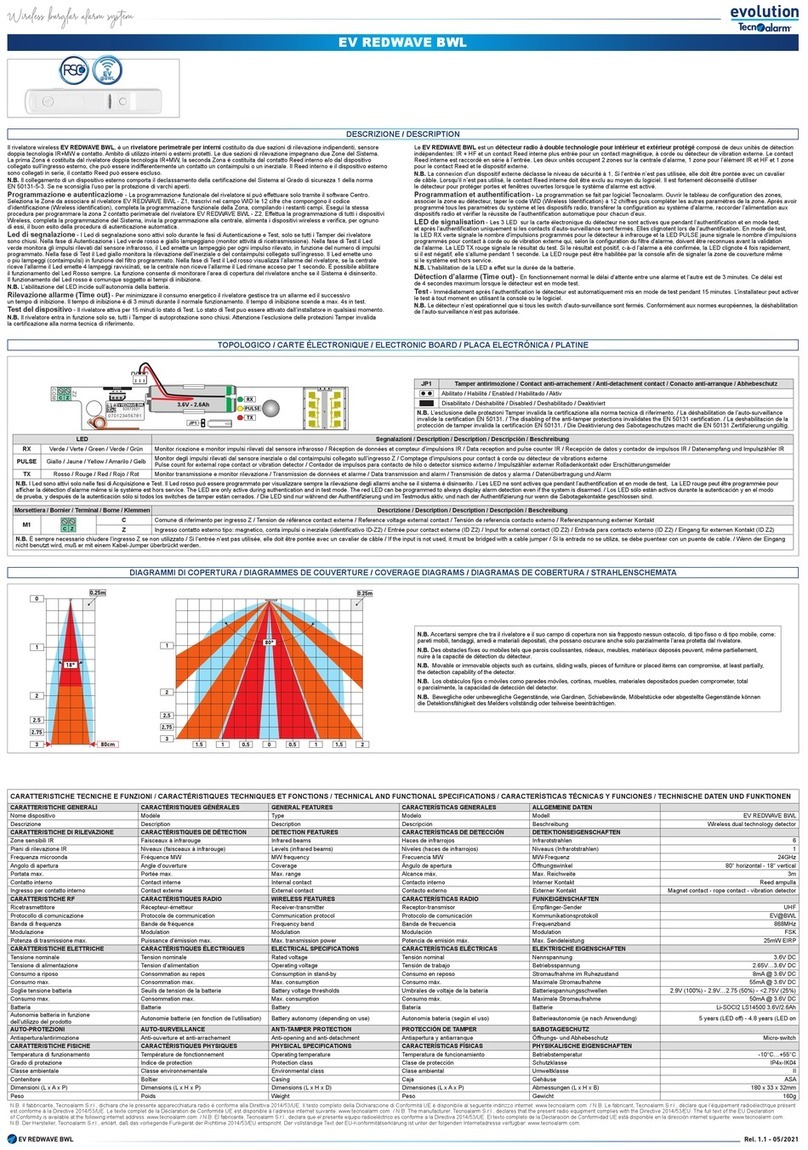
Tecnoalarm EV REDWAVE BWL User manual
Tecnoalarm
Tecnoalarm TP8-64 User manual
Tecnoalarm
Tecnoalarm SIRTEC BUS User manual
