Telect 009-8005-1404 User manual
Dual 200A 4/5 TPA/GMT
Fuse Alarm Panel with
Bay Alarms
Installation Guide

Dual 200A 4/5 TPA/GMT Fuse Alarm Panel
with Bay Alarms
Installation Guide
2
© Telect, Inc. All rights reserved. 126152-5 5.3.17
509.926.6000 :: www.telect.com
Model 009-8005-1404
Installation Guide, Part Number 126152-5
Copyright 2017, Telect, Inc., All Rights Reserved
Telect and Connecting the Future are registered trademarks of Telect, Inc.
22425 East Appleway Ave. # 11
Liberty Lake, WA 99019
Telect assumes no liability from the application or use of these products. Neither does Telect convey any
license under its patent rights nor the patent rights of others. This document and the products described
herein are subject to change without notice.
Connecting the future for over 30 years
Telect challenges the status quo and looks beyond what is possible in network connectivity and
power management.
Founded in 1982, Telect is driven by the principles of innovation and customer service. Headquartered in
Liberty Lake, WA, the privately held company supports a global network of customers with a
comprehensive product portfolio and a values-driven corporate culture.
Our products and solutions are found across communications service-provider networks, data centers
and utility networks around the globe.
At Telect, we pride ourselves on our ability to respond to customer challenges, building a reputation
among communications service providers for delivering solutions uniquely tailored to their needs.
We simplify networks.™
• Custom configured solutions
• Products integrate seamlessly into existing infrastructure
• Exceptional customer service
• Hassle-free warranty
Technical Support
Email: getinfo@telect.com
Phone: 509-926-6000

Dual 200A 4/5 TPA/GMT Fuse Alarm Panel
with Bay Alarms
Installation Guide
3
© Telect, Inc. All rights reserved. 126152-5 5.3.17
509.926.6000 :: www.telect.com
Table of Contents
1.1 Overview .................................................................................................................................................1
1.2 Inspection................................................................................................................................................1
1.3 Specifications..........................................................................................................................................2
1.4 Installation...............................................................................................................................................4
1.5 Accessories...........................................................................................................................................10
1.6 Schematic Drawing ...............................................................................................................................11
1.7 Assembly Drawing ................................................................................................................................12
List of Figures
Figure 1 –Model 009-8005-1404..................................................................................................................1
Figure 2 –Bracket Orientation......................................................................................................................4
Figure 3 –Rack Mounting.............................................................................................................................4
Figure 4 –Ground Lug Connection...............................................................................................................5
Figure 5 –Input Lugs ....................................................................................................................................5
Figure 6 –Disengaging a TPA Fuse Holder.................................................................................................6
Figure 7 –Alarm Indicators...........................................................................................................................6
Figure 8 –Alarm Terminals...........................................................................................................................6
Figure 9 –TPA Output Lug Connections......................................................................................................7
Figure 10 –GMT Output Lug Connections...................................................................................................7
Figure 11 –Installing TPA Fuses..................................................................................................................8
Figure 12 –Installing GMT Fuses.................................................................................................................8
Figure 13 –Designation Card.......................................................................................................................9

Dual 200A 4/5 TPA/GMT Fuse Alarm Panel
with Bay Alarms
Installation Guide
4
© Telect, Inc. All rights reserved. 126152-5 5.3.17
509.926.6000 :: www.telect.com
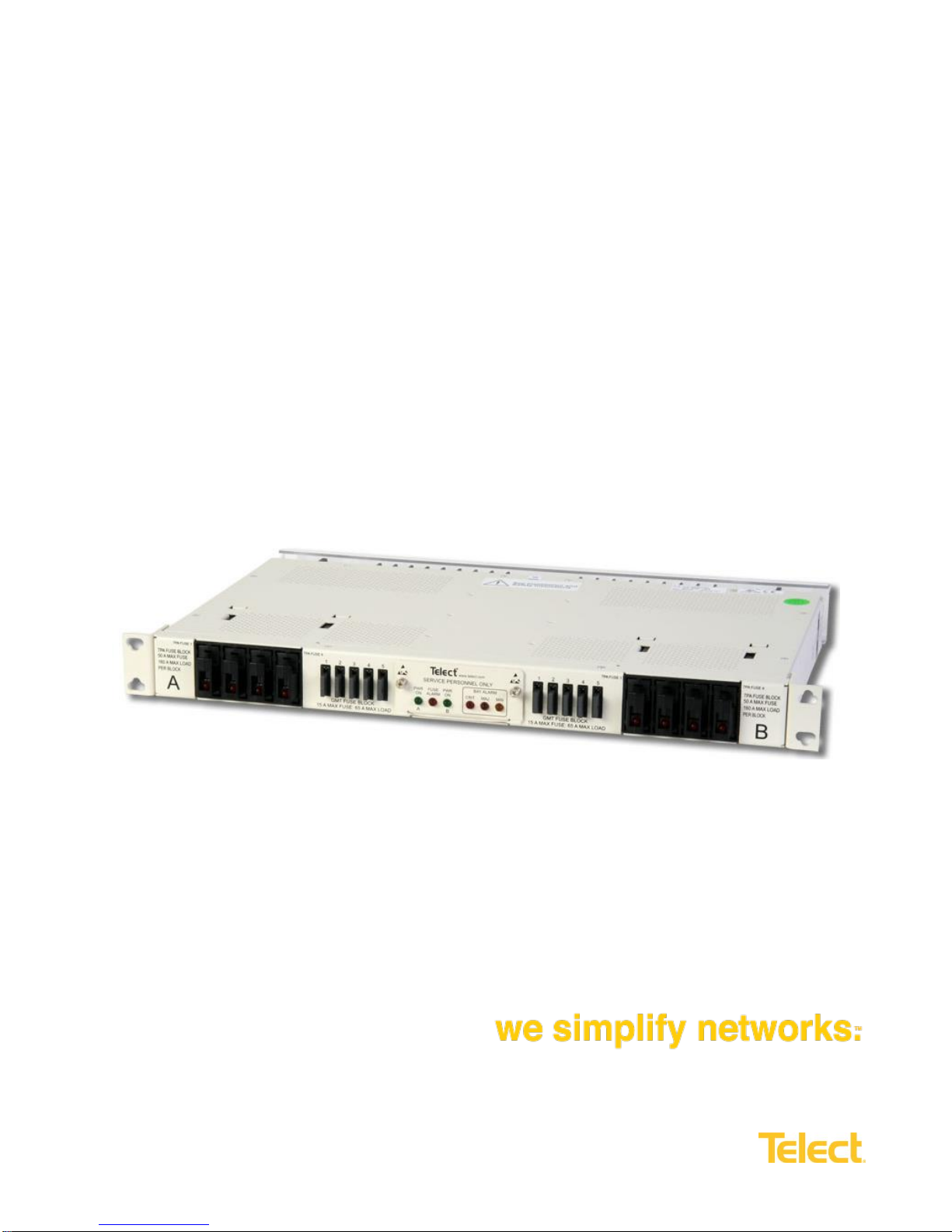
1.1 Overview
The Telect dual-feed 200A fuse panel with
alarms provide power protection for a
variety of telecommunications equipment.
Panel includes 8 TPA output fuse holders
(4 per side) and 10 GMT fuse holders
(5 per side). Sides A and B are electrically
independent except for the replaceable
alarm card which contains power, fuse
and bay alarm LEDs. Also included are
fuse alarm, power-fail and critical-major-
minor bay alarm relay terminals for wiring
to external indicators.
Hardware is included for flush or extended mounting in 19"or 23"relay racks. Visit our website for
ordering Telect accessories and replaceable parts: output fuses (3A-50A TPA; ¼A-15A GMT), dummy
fuses, lugs, ETSI mounting kit and more.
Model 009-8005-1404 is UL listed, File E 139903 V1 S9.
1.2 Inspection
Please read these instructions carefully before beginning installation. If you need assistance, call
Technical Support at 509-926-6000 or email Telect at [email protected].
Inspect equipment after unpacking and compare it to the packing list.
Immediately report any shipping damage, defects or missing parts to Telect at 509-926-6000. Keep all
documentation that comes with your shipment.
Telect is not liable for shipping damage. If the product is damaged, please notify the carrier and call
Telect Customer Service at 509-926-6000 for further recourse.
NOTE: For service or warranty information, please visit the telect.com website and click on the “Support”
Front
Rear
Figure 1 –Model 009-8005-1404

Dual 200A 4/5 TPA/GMT Fuse Alarm Panel
with Bay Alarms
Installation Guide
5
© Telect, Inc. All rights reserved. 126152-5 5.3.17
509.926.6000 :: www.telect.com
1.3 Specifications
Inputs:
Specifications:
Voltages & range
+/- 24 VDC, +/- 20V to +/- 30V
-48 VDC, -40V to -60V
Max. input load rating
200A per side
Nominal power dissipation at
full load
70W per side @ 9600W full load per side (200A x 48V)
Percentage of full load power
dissipation at nominal voltage
Less than 1%
Max. input interrupt device
250A
Input terminal studs (with split ring
lock washers & nuts) for
dual-hole compression lugs
Two pairs of ¼ -20 studs on ¾ in. centers. Torque nut (using 7/16
in. or 12 mm socket) to ~45 in. -lb. (~5 N•m).
Input wire size
#8 to 250MCM AWG (depends on input interrupt device)
TPA Outputs:
Specifications:
Max. TPA output fuse (ea.)
50A
Max. TPA output load
(ea.) –continuous
40A
Max. total TPA output load
160A per side
TPA output terminal studs with nuts
16, single, #10 –32 studs, max. lug width of 0.46 in. (1.17 cm).
Torque nut using 3/8 in. or 10 mm socket to ~20 in.-lb.
(~2.3 N•m)
TPA output wire size
#18 to #6 AWG (depends on output fuse rating)
Grounding:
Specifications:
Earth GND terminal studs (with split
ring lock washers & hex nuts) for
dual-hole compression lug
Two pair of ¼ - 20 threaded holes on ⅝ in. (1.59 cm) centers.
Torque supplied bolt (using 7/16 in. or 12 mm socket) to 4 ft-lb
(5.42 N•m)
Ground wire size
Up to #4 AWG (depends on input interrupt device)
Dual 200A 4/5 TPA/GMT Fuse Alarm Panel
with Bay Alarms
Installation Guide
6
© Telect, Inc. All rights reserved. 126152-5 5.3.17
509.926.6000 :: www.telect.com
1.3 Specifications cont.
GMT Outputs:
Specifications:
Max. GMT output fuse (ea.)
15A
Max. GMT output load
(ea.), continuous
12A
Max. total GMT output load
65A per side
GMT output terminal (wire binding)
20, #6 panhead screws, max. lug width of .32 in. (.81 cm).
GMT output wire size
#20 to #12 AWG (depends on output fuse rating)
Alarms:
Specifications:
Alarm relay contacts
2A @ 30 VDC
0.6A @ 60 VDC
Max. alarm card power rating
@20V: 85mA (1.70W)
@24V: 103 mA (2.47W)
@27V: 109 mA (2.94W)
@30V: 112 mA (3.36W)
@42V: 123 mA (5.17W)
@48V: 128 mA (6.14W)
@56V: 135 mA (7.56W)
@60V: 139 mA (8.34W)
Alarm wire size
#24 AWG, type (#26 to #20 AWG)
Alarm terminals
Wire wrap
Dimensions:
Specifications:
Nominal, without brackets: * Width
Height
Depth
* See Page 12 for exact dimensions
17.25 in. (43.82 cm)
1.75 in. (4.44 cm)
10 in. (25.40 cm)
Weight:
Specifications:
Weight, without packaging
~14 lb. (~6 kg)
Weight, shipping
~15 lb. (~7 kg)
Environment:
Specifications:
Operating temperature range
-10°C (14°F) to 55°C (131°F)
Dual 200A 4/5 TPA/GMT Fuse Alarm Panel
with Bay Alarms
Installation Guide
7
© Telect, Inc. All rights reserved. 126152-5 5.3.17
509.926.6000 :: www.telect.com
1.4 Installation
ALERT! Only qualified personnel may install and maintain this product. Verify all connections meet requirements
specified in local electric codes or operating company guidelines before supplying power. Protect this equipment
with a fuse or breaker sufficient to interrupt the power levels specified on the preceding pages.
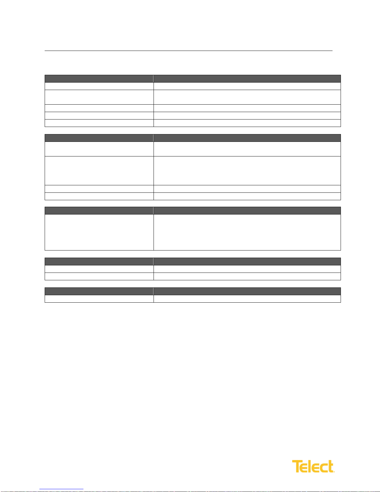
NOTE: Panel brackets provide either flush or extended EIA or WECO mounting in a 19 in. or 23 in. rack. Panel is
configured at the factory for 1 in. extended mounting in a 19-in. rack.
1. If necessary, remove the three screws and reposition/re-align
the brackets on the sides of the distribution panel, as shown
in Figure 2.
2. Locate an unused rack position and mount the panel using the
four screws and lock washers provided, as shown in Figure 3.
(It’s best to mount the panel as high as possible on the rack.)
3. Tighten the screws to 35 in.-lb. (4.29 N•m).
4. Loosen (you need not remove) the two screws securing the
rear terminal cover on the back of the panel.
5. Remove the cover.
WARNING! Failure to properly ground this equipment can create hazardous conditions for installation personnel
and equipment.
ALERT! Only use components and crimping tools approved by agencies or certifying bodies recognized in your
country or region such as Underwriter’s Laboratories (UL), TUV, etc.
Figure 2 –Bracket Orientation
Figure 3 –Rack Mounting

Dual 200A 4/5 TPA/GMT Fuse Alarm Panel
with Bay Alarms
Installation Guide
8
© Telect, Inc. All rights reserved. 126152-5 5.3.17
509.926.6000 :: www.telect.com
6. Use a listed (approved) crimping tool to attach a listed (approved), dual-hole compression lug onto a suitable
ground wire. (Size of the ground depends on the input interruption device. Check local codes and/or operating
company guidelines for proper ground wire and lug size.)
7. Telect recommends that you lightly coach antioxidant on lug
and grounding surface on side of the panel.
8. Then, connect the lug using ¼ - 20 bolt, split ring washer and
flat washer provided, as shown in Figure 4.
9. Tighten the bolt to 4 ft-lb (5.42 N•m).
4
WARNING! Before connecting input power cables, make sure
input power to the panel is turned off.
10. Make sure the input power is off (open breaker, dummy fuse,
open fuse holder at power distribution unit, or PDU, before
connecting this panel’s input cables to the PDU.
11. For input wiring —wiring used as inputs to this distribution panel
—crimp the dual-hole compression lugs onto #8 AWG to 250MCM
copper wires.
12. Insulate lug barrels with UL94 V-0 rated heat shrink tubing.
13. Clean terminals and lugs with a nonabrasive, nonmetallic pad.
14. Telect recommends a light coating of antioxidant on lugs
and input BATTERY and RETURN terminals before
connecting input terminals on back of the panel, as shown
in Figure 5.
15. Tighten the lugs to 15 ft-lb. (22 N•m).
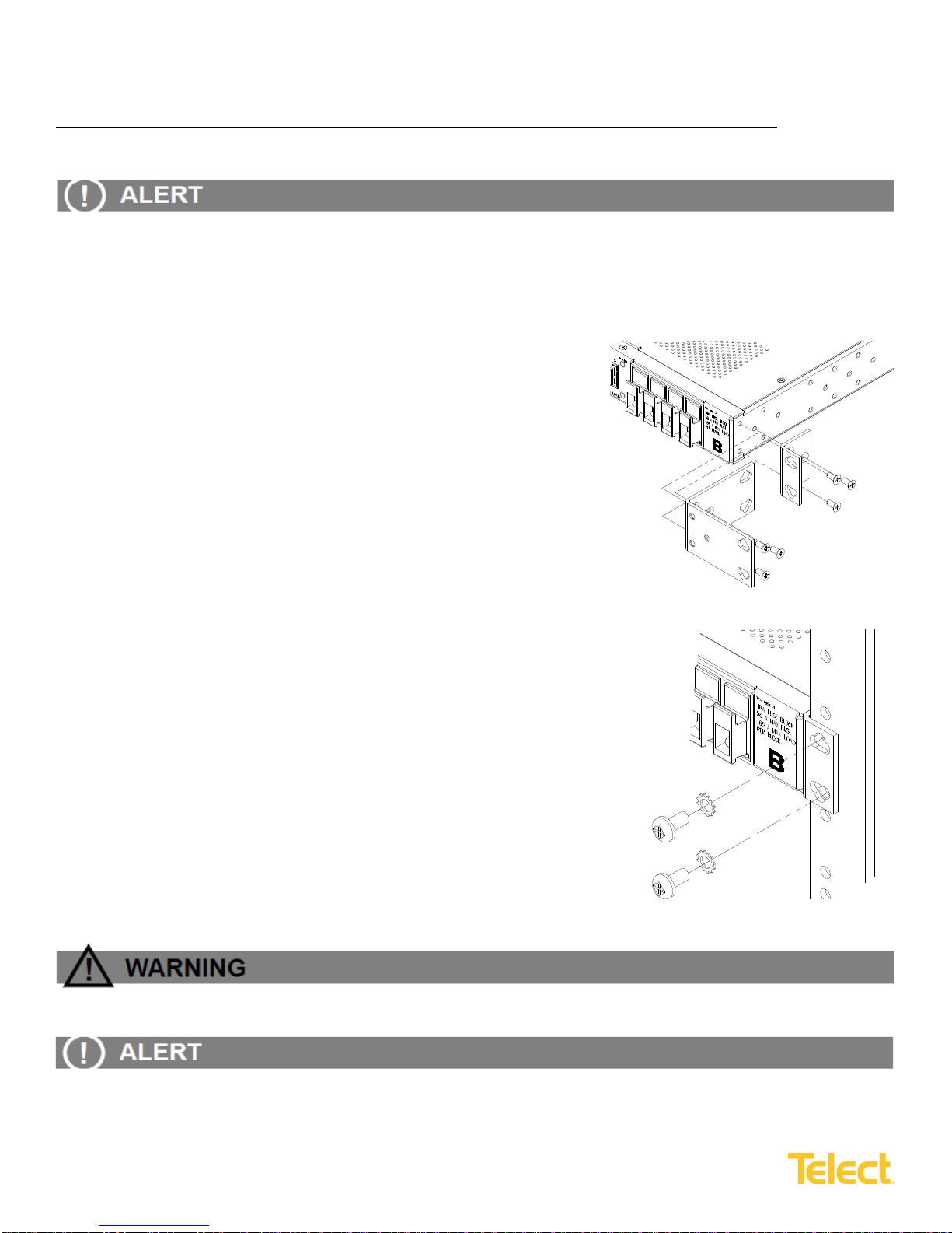
16. Make sure TPA and GMT fuse positions are either empty
or contain phony fuses (inoperative plastic slugs).
If necessary, pull out the TPA carrier about an inch
from its holder to disengage the TPA fuse, as shown
in Figure 6.
Figure 4 –Ground Lug Connection
Figure 5 –Input Lugs
Dual 200A 4/5 TPA/GMT Fuse Alarm Panel
with Bay Alarms
Installation Guide
9
© Telect, Inc. All rights reserved. 126152-5 5.3.17
509.926.6000 :: www.telect.com
17. Enable the fuse or breaker at the PDU (250A max.) to
turn on Feed A to Side A of the panel and then measure
voltage and check polarity at input connectors of the
panel. Also, check that:
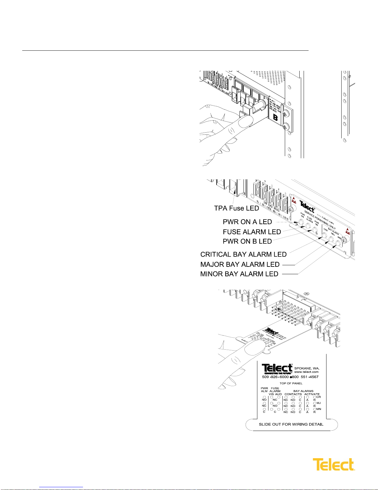
•PWR ON A LED on front of the panel turns on
(green). (See Figure 7 for location.)
•PWR ON B, FUSE ALARM and TPA Fuse LEDs
must be off.
18. At rear of panel, pull to extend plastic reference card
below alarm terminals. (See Figure 8 for location.)
19. With PWR ON A lit (normal operation) —but with
PWR ON B LED off (failure operation) —test the
power-fail relay and contacts at the PWR ALM
terminals on the rear of the panel:
•Expect an open circuit (∞Ω) between Terminals
Cand NC.
•Expect continuity (0Ω) between Terminals
Cand NO.
20. Also, test the fuse alarm relay contacts at the FUSE
ALARM terminals on rear of the panel. For both the VIS
(visual) and AUD (audible) indicator contacts:
•Expect continuity (0Ω) between Terminals C and NC.
•Expect an open circuit (∞Ω) between Terminals Cand NO.
21. Repeat steps 17 through 20 to power up Side B.
PWR ON A and PWR ON B must both be lit.
Figure 6 –Disengaging a TPA
Fuse Holder
Figure 7 –Alarm Indicators
Figure 8 –Alarm Terminals
Dual 200A 4/5 TPA/GMT Fuse Alarm Panel
with Bay Alarms
Installation Guide
10
© Telect, Inc. All rights reserved. 126152-5 5.3.17
509.926.6000 :: www.telect.com
22. With PWR ON A and B lit (normal operation), test the power-fail relay and contacts at the
PWR ALM terminals on the rear of the panel:
•Expect continuity (0Ω) between Terminals Cand NC.
•Expect an open circuit (∞Ω) between Terminals Cand NO.
23. Make sure none of the fuse positions contain fuses.
24. For TPA output wiring, crimp single-hole lugs onto one end of the #18 to #6 AWG copper output wires, as
required by NEC. (Work with one output wire at a time.)
25. Clean the panel terminals and lugs with a nonabrasive, nonmetallic pad.
26. Telect recommends a light coat of antioxidant on the lugs and output BATTERY and RETURN terminals
before connecting lugs to the terminals, as shown in Figure 9. (NEC specifies only one lug and load at
each output terminal.)
27. Tighten nuts to 20 in.-lb. (~2.3 N•m) and then
connect the other end of output wire to load.
28. For GMT output wiring, use #20 to #12 AWG
copper wire. (Work with one wire at a time.) At
the panel end of the wire, either:
•Crimp a single-hole ring or fork lug, as
required by NEC.
OR
•Strip ⅜in. (1 cm) of insulation for a bare
wire connection.
29. Clean the panel terminals and lug (if applicable)
with a nonabrasive, nonmetallic pad.
30. Telect recommends a light coating of antioxidant
on the lug/wire and output BATTERY and
RETURN terminals before connection to the
terminals, as shown for Figure 10. (NEC
specifies only one load at each output terminal.)
31. Tighten the panhead screws to no greater than
8 in.-lb. (~1 N•m) and then connect other end of
the output wire to load.
Figure 9 –TPA Output Lug Connections
Figure 10 –GMT Output Lug Connections

Dual 200A 4/5 TPA/GMT Fuse Alarm Panel
with Bay Alarms
Installation Guide
11
© Telect, Inc. All rights reserved. 126152-5 5.3.17
509.926.6000 :: www.telect.com
ALERT! Local electrical and operating company guidelines recommend that the individual load not exceed 80%
of input over-current device capacity (for example, 50A TPA fuse x .80 = 40A max. load). Total load for all TPA
& GMT outputs on each side must not exceed 200A.
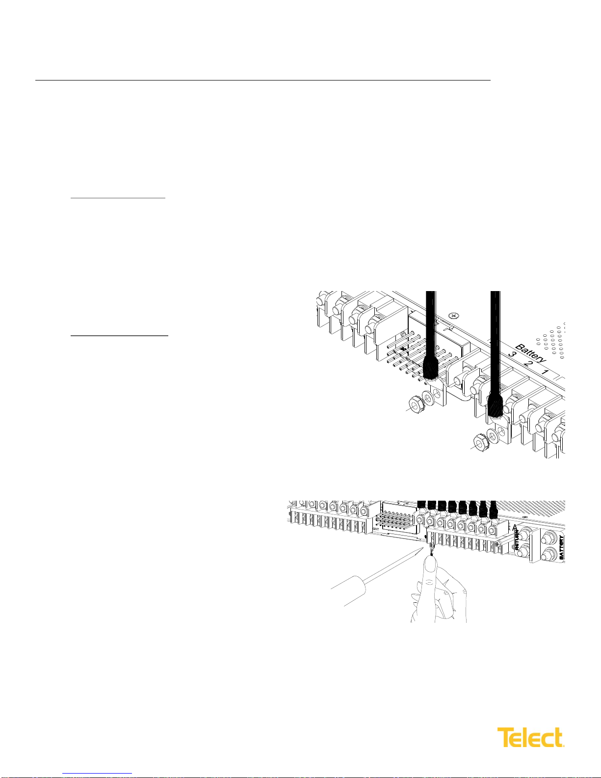
32. Make sure load devices are disabled and then install fuses:
NOTE: Under load, TPA modules are disconnect devices only. Do not use them to reconnect power to enabled
equipment loads. Reconnecting a TPA module under power with an enabled load may damage the TPA module.
•For a TPA fuse, pull out the TPA fuse carrier and
insert an operable fuse, as shown in Figure 11.
•For a GMT fuse, pull out dummy fuse and insert
operable fuse, as shown in Figure 12.
33. Check the voltage and polarity at the input of each
equipment load.
34. If possible:
•Temporarily replace one of the operable TPA fuses
with a blown fuse to check that the FUSE ALARM
and the TPA Fuse LEDs light red.
Also, check the FUSE ALARM terminals on the
rear of the panel:
oExpect an open circuit (∞Ω) between
Terminals Cand NC.
oExpect continuity (0Ω) between Terminals
Cand NO.
Re-install the operable TPA fuse before proceeding.
•Likewise, replace one of the operable GMT fuses with a blown fuse to verify that the FUSE ALARM
LED and FUSE ALARM terminals are also as specified above. Then, re-install the operable GMT fuse
before proceeding.
Dummy
Fuse
GMT Fuse
Figure 11 –Installing TPA Fuses
Figure 12 –Installing GMT Fuses
Dual 200A 4/5 TPA/GMT Fuse Alarm Panel
with Bay Alarms
Installation Guide
12
© Telect, Inc. All rights reserved. 126152-5 5.3.17
509.926.6000 :: www.telect.com
35. If desired, connect the remote external audio/visual alarm indicator wires (solid or tinned wires,
#26 to #20 AWG) to the PWR ALARM and FUSE ALARM terminals.
36. Test the CRIT (critical), MAJ (major), MIN (minor) external alarms on the rear of the panel.
Without any alarm conditions:
•Expect the CRIT, MAJ and MIN LEDs to be off
•Expect continuity (0Ω) between Cand NC of each set of terminals
•Expect an open circuit (∞Ω) between Cand NO of each set of terminals
37. Jumper A(activate) terminal to corresponding R(return) terminal of CRIT, MAJ and MIN.
When each pair of A and Rterminals are jumpered:
•Expect CRIT and MAJLEDs to turn red and MIN to turn amber
•Expect an open circuit (∞Ω) between Cand NC of each set of terminals when the relays are activated
•Expect continuity (0Ω) between Terminals C
and NO when relays are activated
38. Connect Aand Rpairs to appropriate, corresponding
“dry” contacts of equipment relays powered by this
breaker panel.
39. Connect wiring (#26 to #20 AWG) to external alarm
switch contacts (Terminals NO, NC and C) of CRIT,
MAJ and MIN.
40. Carefully re-install the rear cover.
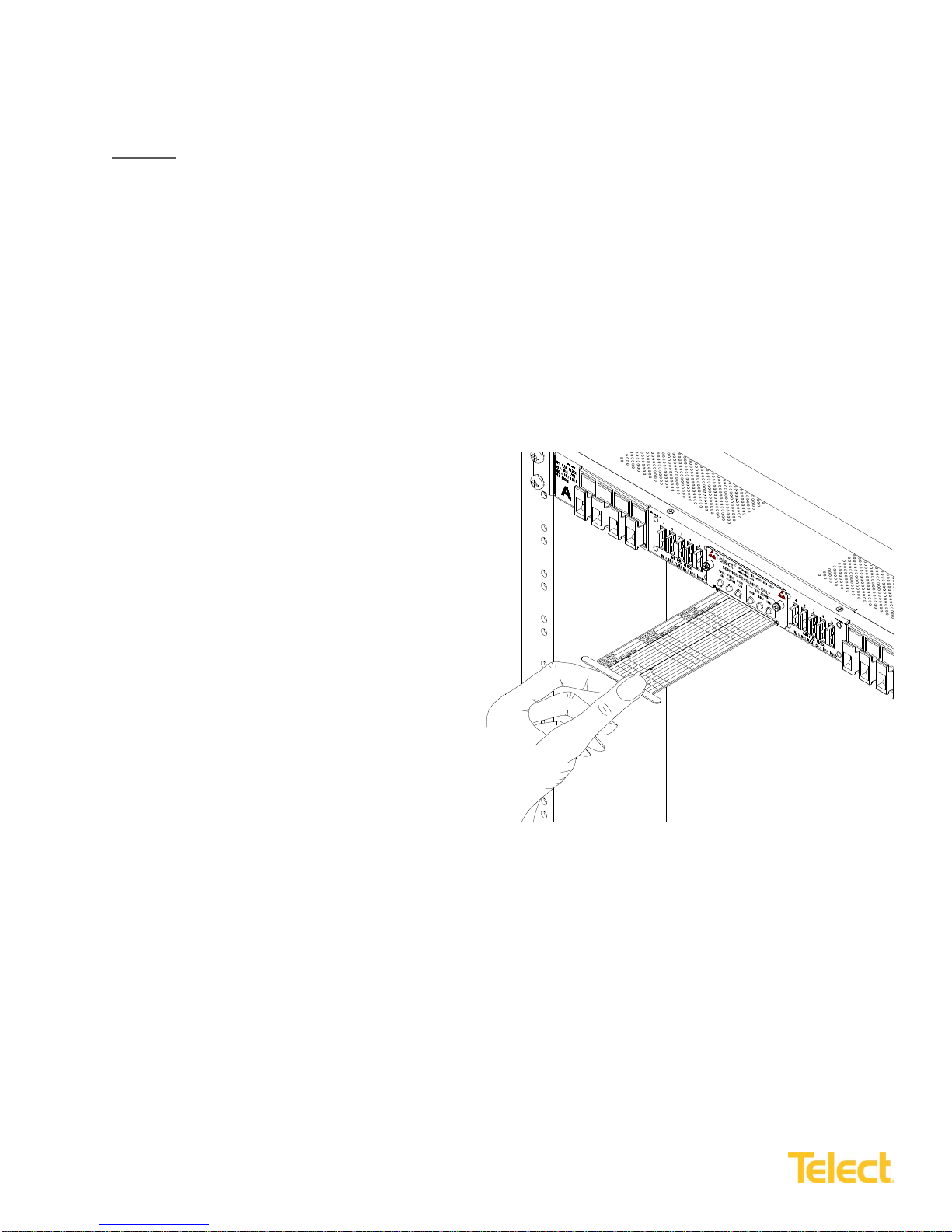
41. Record TPA and GMT output destinations on the
pull-out designation card below front panel LEDs,
shown in Figure 13.
42. Turn on equipment loads one at a time to verify
proper operation of loads.
Figure 13 –Designation Card

Dual 200A 4/5 TPA/GMT Fuse Alarm Panel
with Bay Alarms
Installation Guide
13
© Telect, Inc. All rights reserved. 126152-5 5.3.17
509.926.6000 :: www.telect.com
1.5 Accessories
The following lists optional and replacement items for the panel. For compression lugs, please refer to Wire Sizing &
Label Convention Chart (Telect Part No. 117995) included with your panel.
Item
Description
Part Number
Alarm card, WHT with Bay Alarms
PWR / FUSE / BAY ALARM LEDs & Contacts
400547
TPA Fuses
5A
124818
10A
124819
15A
124820
20A
124821
30A
122734
40A
122738
50A
122739
GMT Fuses
¼A Violet (VIO)
100151
½A Red (RED)
004001
¾A Brown (BRN)
004008
1A Gray (GRY)
100991
1 ⅓A White (WHT)
004006
1 ½A White/Yellow (WHT/YEL)
004011
2A Orange (ORN)
004002
3A Blue (BLU)
004012
4A White/Brown (WHT/BRN)
004013
5A Green (GRN)
004014
7 ½A Black/White (BLK/WHT)
004010
10A Red/White (RED/WHT)
004015
12A Yellow/Green (YEL/GRN)
102287
15A Red/Blue (RED/BLU)
102288
Dummy, Phony, Plastic Slug
132748
Safety Covers
116915
ETSI Mounting Brackets
Black
090-0041-0030
White
090-0041-0031
Designation Card
For recording outputs
119807

Dual 200A 4/5 TPA/GMT Fuse Alarm Panel
with Bay Alarms
Installation Guide
14
© Telect, Inc. All rights reserved. 126152-5 5.3.17
509.926.6000 :: www.telect.com
1.6 Schematic Drawing
C
ACTIVATE
NOTE 1: NC & NO Alarm switches are shown in
normal operating state (without failures or alarms).
NOTE 2: Layout of rear-access terminals in this schematic does not
represent the physical arrangement on the rear of the panel.
NOTE 3: Operational power for the monitoring and activation of all fuse,
bay, and power alarms is obtained from combining Input A and
Input B sources. Either Input A or Input B is individually sufficient
for complete operation of all alarm circuits.
NO
NC
C
PWR
ALARM FUSE
ALARM BAY ALARMS
CONTACTS ACTIVATE
NO NO
NC
CNC
NC NO
C
C
A
A
R
R
REMOVEABLE ALARM CARD
BATT
RTN
RTN
BATT
1
2
3
4
1
2
3
4
1
2
19
20
1
2
19
20
1
2
19
20
1
2
19
20
1
2
3
4
1
2
3
4
TPA OUTPUT
BATT A
INPUT A
TPA OUTPUT
RTN A
GMT OUTPUT
BATT A
GMT OUTPUT
RTN A
GMT OUTPUT
RTN B
GMT OUTPUT
BATT B
TPA OUTPUT
RTN B
TPA OUTPUT
BATT B
INPUT B
POWER ON A
POWER ON B
TPA/GMT FUSE ALARM CR
MJ
MN
TPA FUSE
HOLDER
LEDS
TPA FUSE
HOLDER
LEDS
C GND
CRITICAL
MAJOR
MINOR
BAY
ALARM
GMT Amp Size Color Code
¼ Violet (VIO)
½ Red (RED)
¾ Brown (BRN)
1 Gray (GRY)
1 1/3 White (WHT)
1 ½ White/Yellow (WHT/YEL)
2 Orange (ORN)
3 Blue (BLU)
4 White/Brown (WHT/BRN)
5 Green (GRN)
7 ½ Black/White (BLK/WHT
10 Red/White (RED/WHT)
12 Yellow/Green (YEL/GRN)
15 Red/Blue (RED/BLU)
CRITICAL BAY
BREAKER
MINOR BAY
MAJOR BAY
NC
NO
RTN
ACTIVATE
CALARM
NO
NC
RTN
ACTIVATE
CALARM
NO
NC
C
ALARM
AUDIBLE ALARM
NO
NC
NC
NO
C
CVISUAL
ALARM
POWER
NO
RTN
NC

Dual 200A 4/5 TPA/GMT Fuse Alarm Panel
with Bay Alarms
Installation Guide
15
© Telect, Inc. All rights reserved. 126152-5 5.3.17
509.926.6000 :: www.telect.com
1.7 Assembly Drawing
•
Telect assumes no liability from the application or use of these products. Neither does Telect convey any license under its
patent rights or the patent rights of others. This document and the products described herein are subject to change
without notice.
#8 - 36 Stud & Nut (Use 5/16" Socket)
1/4 - 20 Stud
#6 Panhead
NOTES:
1. Dimensions are in or in. (cm)
(cm)
in.
2. Panel not supplied with fuses.
REAR VIEW
(ROTATED)
TOP VIEW
FRONT VIEW Universal Bracket Reversed for 23" Rack
Holes Accommodate
EIA/WECO Mounting Patterns
Pull-Out Designation Card Below
Replacable Alarm Board
1.72
(4.37)
1.00
(2.54)
23.00 (58.42)
22.31 (56.67)
19.00 (48.26)
18.31 (46.51)
17.25 (43.82)
11.86
(30.14)
0.10
(0.25)
1.00
(2.54)
2.00
(5.08)
1.00
(2.54)
0.39 (0.98)
10.01
(25.42)
1.15
(2.92)
T
P
AP
A
T
GMT GMT
0.75
(1.90)
0.46
(1.17)
0.32
(0.81)
Table of contents
Other Telect Security System manuals


 manual")


