manuals.online logo
Brands
  1. Home
  2. •
  3. Brands
  4. •
  5. Vimar
  6. •
  7. Security System
  8. •
  9. Vimar BY-ALARM PLUS User manual

Vimar BY-ALARM PLUS User manual

Viale Vicenza 14
36063 Marostica VI - Italy
www.vimar.com
49401879A0 01 2212
03827
BY-ALARM PLUS
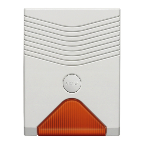
By-alarm self-powered outdoor siren, can be connected to any burglar alarm
system control unit, 2 piezoelectric speakers, LED alarm signalling, 13.8 Vdc
power supply, surface mounting. Buffer battery not included. Spirit level for
easy installation, system status LED, anti-tamper protection, anti-removal and
anti-foam, 4 programmable sounds, 2 programmable timers.
The siren is self-powered and managed by a microprocessor that can continuously monitor all
device parameters. It has a volt-free changeover relay specifically for signalling tampering when
integrated with other systems, and a fault output for remote monitoring of fault conditions. The
activation method can be set freely (e.g. 2-wire, 3-wire, etc.) as can the signalling method. The
siren is pre-configured with default factory settings, which can be changed using the internal
push buttons.
CONNECTIONS
2-wire connection
This is the classic connection method in which the alarm signal is active when there is no power
supply positive (see the figure CONNECTIONS - 2-wire connection).
3- or 4-wire connection
This connection method offers greater flexibility to activate/deactivate the siren and a second
siren (the figure CONNECTIONS - 3- or 4-wire connection). In this case, the parameters are
programmed using the By-alarm Plus Manager software.
Activation: this can be done by either disconnecting the power supply + or using the START
input (which is driven by the control unit).
Deactivation: this can be done by either reconnecting the power supply + or using the STOP
input (which is driven by the control unit).
Both the START and STOP terminals can be programmed as described in the PROGRAMMING
paragraph.
Any alarm can be stopped with the "STOP" input. The STOP input stops alarm signalling as long
as it is kept active; for example, if the input is deactivated, the siren will sound again if the cause
of activation is still present.
The figure also shows how to simultaneously activate both the external siren and an optional
internal siren using the volt-free changeover contacts COM-NC-NO of the control unit relay;
switching the relay disconnects the + from the external siren and simultaneously connects it to
the internal siren.
Other connections
If you want to take the tamper signal to the control unit, connect terminals "7" and "8" on the
siren directly to a terminal on the control unit. The contact connected to terminals "7" and "8"
opens in the event of tampering.
SIREN BATTERY (NOT INCLUDED)
This powers the siren in the event of tampering and/or no mains voltage on the line connecting
to the rest of the system. It must always be present since, in the event of an alarm, it supplies
the energy necessary to develop the required sound power and to supply the flashing light. The
12 V power supply keeps it charged.
178
0,5
35
0,5
60
0,5
N.B. Always observe the polarity during installation (red = positive, black = negative).
If the battery is flat and its voltage is lower than 10.5 V, the siren stops sounding, while the light
indicators remains on.
INSTALLATION
1. Choose a suitable location to install the device. Position the siren on a flat surface, in a
place that is hard to access but clearly visible so that it acts as a deterrent against attempted
break-ins.
2. Cut off the power supply to the electrical system.
3. Remove the cover.
4. Route the cables through the cable outlet holes.
5. If you want to activate the anti-removal protection, insert the screw into the corresponding
hole; take care to position the microswitch lower than the screw.
6. Insert the buffer battery into its housing and wire it with the correct polarity.
7. Wire the siren.
8. Check whether the default settings are what you want, and make any necessary changes
(refer to the PROGRAMMING chapter). Power up the siren; red LED DL7 will remain on
during this step.
9. Close the cover, taking care to centre the holes, and tighten the screws provided. The
anti-tamper microswitch will close and LED DL7 (red) will flash every 2 s for 20 s; when the
flashing stops, the siren is ready and operational.
PROGRAMMING
The siren is programmed using the push buttons and LEDs on the electronic board.
START
D11
12
DL7
ES01 ES02
R4
E
CPH1
IR1 IR2
OP1
1
P1 P2
LABEL (FW)
IN325-R1
LABEL (QC)
23456
R5 R6 R7 R8 R9
D
BATTERY
S
STOP LED FAULT
TAMPER
The programming menus can be recognised by a combination of LED flashes (from 3 to 6), and
push buttons P1 and P2 are used to navigate within the menus.
Programming is only done after initial power-up, so make sure that:
• the siren is not powered, i.e. the battery and power supply are disconnected;
•the anti-tamper switch is open;
•the control unit is in a state that allows tampering with the siren without triggering an alarm (e.g.
control unit in the programming state).
1. Open the cover.
2. Power up the siren; the red LED will remain on.
3.Press push button P1 and hold it down for 3 s; the LEDs will flash to indicate that programming
is active. Release the push button; the combination of LEDs on indicates the current menu (as
specified in the table below).
4.To scroll through the menus to the one you want, press push button P1 until you see the
corresponding LED combination.
5.To enter the current configuration in the selected menu, press push button P2 and release
it. You will then be in the menu, and each press of push button P2 will change the selected
configuration, which is shown by the flashing LEDs.
6.To exit from the current menu and return to the menu selection, press push button P1 and
release it.
7.To exit from programming mode and save the settings, press push button P1 and hold it down
for 3 s until the LEDs flash. To exit from programming mode without saving the changes made,
press push button P2 and hold it down for 3 s until the programming LEDs flash, or wait for
the 30 s timeout without pressing any push buttons.
8.Close the cover and complete the installation.
Below is a list of all programming menus and the corresponding combination of LEDs 3, 4, 5
and 6. The “Options” column contains the programmable settings for each menu (the options
enabled by default are identified with a grey background).
= LED on continuously = LED flashing = LED off
Menu Options
No.
LED
combination
Item
3456345634563456
3 4 5 6
1 START input Negative
rising edge
Positive
rising edge
Negative
falling edge
Positive
falling edge
2STOP
input
Negative
rising edge
Positive
rising edge
Negative
falling edge
Positive
falling edge
3Sound signal-
ling Sound 1 Sound 2 Sound 3 Sound 4
4Maximum
sound duration 3 minutes 6 minutes 9 minutes 12 minutes
5Activate
START input LED DL7 LED DL8 Flashing
light Siren
6No
power supply
FAULT
output
TAMPER
output
Flashing
light Siren
7
Tamper/removal
signal,
anti-foam,
thermal attack
FAULT
output
TAMPER
output
Flashing
light Siren
8
Courtesy
light on
LED line tran-
sition
Activate
LED DL8
only
Activate
combina-
tion of
LED DL8
and
Flashing
light for 10 s
Activate only
Flashing
light for 10 s
/
9Reset to default Default
Viale Vicenza 14
36063 Marostica VI - Italy
www.vimar.com
49401879A0 01 2212
FRONT VIEW (with the cover open)
A: Connection terminals (see the TERMINALS figure for details)
B: Battery cables
C: Anti-foam device
D: Status LED DL8 - Green
E: Anti-tamper/anti-removal device
F: Status LED DL7 - Red
G: Push buttons P1, P2 and programming LEDs
OPERATION
The siren performs different kinds of optical and acoustic signalling; these signalling modes are
activated or not according to how the siren and control unit are programmed. All parameters
of each signalling mode are therefore programmable, and may be single, combined with other
signals or deactivated.
SIGNALLING TYPES
Flashing light
The high-intensity light signal is generated by a stroboscopic flash. The flashing light is activated
with a frequency of 36 flashes per minute when there is no power (power supply "+" and "-"
cut off), in the event of tampering or when activated via the "START" terminal, if programmed
to do so.
In courtesy light mode, it follows the state of the "LED" terminal and remains active for 10 s.
Status LED
There are two auxiliary LEDs at the sides of the flashing light, which serve to indicate alarms and
to support programming.
LED DL7 (red) behaves as follows during programming:
• On continuously = programming mode active and cover open.
• Flashing = exited from the programming menu, start of the time that is insensitive to external
stimuli, after which the siren will return to normal operation.
During normal operation, the status LED is activated by a signal on the START terminal (if pro-
grammed to do so).
LED DL8 (green) behaves as follows during normal operation:
• it lights under control from the LED terminal.
• it lights under control from the START terminal, if programmed to do so.
Programming LED
LEDs 3, 4, 5 and 6 show the current programming step and when the settings have been
saved.
Acoustic signalling
The sound type can be programmed (from 4 different types) in combination with the optical
signalling of the flashing light.
SIREN ACTIVATION
The sirens can be activated from either the control unit or events generated by the siren itself.
Activation ends when one of the following conditions occurs:
- the rest condition is restored
- the maximum alarm time lapses (which only stops the alarm sound)
Siren events
Siren 03827 generates events that can be associated with one or more signalling modes.
Siren event Action/signalling
No power Programmable. Refer to the table in
PROGRAMMING
Battery problems FAULT output activated
Anti-foam device dirty FAULT output activated
Siren tampering:
- cover opening/ripping from the wall
- anti-foam
- thermal attack (rapid temperature increase/
decrease; oxygen lance or forced freezing)
Programmable. Refer to the table in
PROGRAMMING
No power
This is the most commonly used mode because it uses few connections but guarantees pro-
tection against cutting the wires. In this activation mode, the siren signals when it detects a loss
of primary power. The available signalling can be programmed as required.
LED input
This input (active low) is an auxiliary channel though which the control unit can activate signalling
on status LED DL8 (green).
INSTALLATION RULES
Installation must be carried out by qualified persons in compliance with the current regulations
regarding the installation of electrical equipment in the country where the products are installed.
CHARACTERISTICS
• Power supply voltage:
- rated: 13.8 V
- range: 9 to 16 V
• Absorption:
- 220 mA during operation
- 140 mA on stand-by
• Sound pressure level: 108 dB
• Sound frequency: 2 Hz/3000 Hz
• Flashes per minute: 36
• Battery that can be accommodated: 12 Vdc 2.1 Ah flammability class UL94-HB
• 2 piezoelectric speakers
• Stroboscopic flashing light
• Anti-tamper device
• Anti-removal device
• Plastic enclosure
• Battery monitoring and charging based on the ambient temperature
WEEE - User information
The crossed bin symbol on the appliance or on its packaging indicates that the product at the end of its life must be collect-
ed separately from other waste. The user must therefore hand the equipment at the end of its life cycle over to the appro-
priate municipal centres for the differentiated collection of electrical and electronic waste. As an alternative to independent
management, you can deliver the equipment you want to dispose of free of charge to the distributor when purchasing a
new appliance of an equivalent type. You can also deliver electronic products to be disposed of that are smaller than 25
cm for free, with no obligation to purchase, to electronics distributors with a sales area of at least 400 m2. Proper sorted
waste collection for subsequent recycling, processing and environmentally conscious disposal of the old equipment helps
to prevent any possible negative impact on the environment and human health while promoting the practice of reusing and/
or recycling materials used in manufacture.
TERMINALS
+: Power supply positive. It also acts as an alarm terminal in 2-wire connections.
D/START: Terminal with programmable polarity to active alarm signalling.
S/STOP: Terminal with programmable polarity to deactivate all signalling.
-: Power supply negative.
LED: Input to activate the LEDs.
FAULT: Terminal for fault signalling. Wire it to an input terminal configured as normally
closed.
TAMPER: Terminals for tamper signalling. Configure the tamper input as normally closed.
• 4 programmable sound signalling modes
• Alarm activation input (START)
• Forced signalling deactivation input (STOP)
• Auxiliary signalling LED activation input (LED)
• Programmable START, STOP input polarity
• Tamper signal output
• Fault signal output
• Operating temperature: -25 to +60 °C
• IP34 protection level
• Safety class: 2
• Environment class: IV
• Dimensions (W x H x D): 218 x 237 x 54.7 mm
REGULATORY COMPLIANCE.
EMC directive. RoHS directive.
Standards EN 62368-1, EN 50130-4, EN 50130-5, EN 55032, EN 50131-4, EN IEC 63000.
REACH (EU) Regulation no. 1907/2006 – Art.33. The product may contain traces of lead.
A
B C
D
EF
G
START
D11
12
DL7
ES01 ES02
R4
E
CPH1
IR1 IR2
OP1
1
P1 P2
LABEL (FW)
IN325-R1
LABEL (QC)
23456
R5 R6 R7 R8 R9
D
BATTERY
S
STOP LED FAULT
TAMPER
START
D11
12
DL7
ES01 ES02
R4
E
CPH1
IR1 IR2
OP1
1
P1 P2
LABEL (FW)
IN325-R1
LABEL (QC)
23456
R5 R6 R7 R8 R9
D
BATTERY
S
STOP LED FAULT
TAMPER
Viale Vicenza 14
36063 Marostica VI - Italy
www.vimar.com
49401879A0 01 2212
CONNECTIONS
2-wire connection
3- or 4-wire connection
RESET
POWER-IN
TAMPER
P1
FACTORY
P1
SERV/ENR SERV/ENR
13
T1 T2 T3 T4
T5 AUX2 AUX3 T6 T7 T8 T9 T10
14 15 16 17 18 19
20 21 22 23 24 25 26 27 28 29 30 31 32 33 34 35 36
VOICE CARD
03812
EXE BUS POWER
P1
NO
COM OC1 +
1 3 4 5 6 7 12
AUX
11
-
10
S
9
D
8
NC
2
+OC OC2
START
D11
12
D
BATTERY
S
STOP LED FAULT
TAMPER
SIREN
03827
CONTROL UNIT
03800-03801-03802
RESET
POWER-IN
TAMPER
P1
FACTORY
P1
SERV/ENR SERV/ENR
13
T1 T2 T3 T4
T5 AUX2 AUX3 T6 T7 T8 T9 T10
14 15 16 17 18 19
20 21 22 23 24 25 26 27 28 29 30 31 32 33 34 35 36
VOICE CARD
03812
EXE BUS POWER
P1
NO
COM OC1 +
1 3 4 5 6 7 12
AUX
11
-
10
S
9
D
8
NC
2
+OC OC2
T T INT SET + –
START
D11
12
D
BATTERY
S
STOP LED FAULT
TAMPER
SIREN
03827
CONTROL UNIT
03800-03801-03802
INTERNAL SIREN
30526-20496-19496-14496
Viale Vicenza 14
36063 Marostica VI - Italy
www.vimar.com
49401879A0 01 2212
INSTALLATION
12V 2AH
1.
2. 3.
WARNING:
Dispose of batteries in the specific separate collection bins.

Other manuals for BY-ALARM PLUS

19

This manual suits for next models

1

Other Vimar Security System manuals

Vimar BY-ALARM PLUS User guide

Vimar

Vimar BY-ALARM PLUS User guide

Vimar BY-ALARM PLUS User guide

Vimar

Vimar BY-ALARM PLUS User guide

Vimar 6260.16P.02 Assembly instructions

Vimar

Vimar 6260.16P.02 Assembly instructions

Vimar 0K03800.02 User guide

Vimar

Vimar 0K03800.02 User guide

Vimar By-alarm 01703.DE User manual

Vimar

Vimar By-alarm 01703.DE User manual

Vimar BY-ALARM PLUS User manual

Vimar

Vimar BY-ALARM PLUS User manual

Vimar 46KIT.036C User manual

Vimar

Vimar 46KIT.036C User manual

Vimar ELVOX 46936.001 User manual

Vimar

Vimar ELVOX 46936.001 User manual

Vimar BY-ALARM PLUS User manual

Vimar

Vimar BY-ALARM PLUS User manual

Vimar ELVOX TVCC User manual

Vimar

Vimar ELVOX TVCC User manual

Vimar By-alarm 01715 User manual

Vimar

Vimar By-alarm 01715 User manual

Vimar BY-ALARM PLUS User manual

Vimar

Vimar BY-ALARM PLUS User manual

Vimar 62IF User manual

Vimar

Vimar 62IF User manual

Vimar 46KIT.436WF User manual

Vimar

Vimar 46KIT.436WF User manual

Vimar BY-ALARM PLUS User manual

Vimar

Vimar BY-ALARM PLUS User manual

Vimar BY-ALARM PLUS User manual

Vimar

Vimar BY-ALARM PLUS User manual

Vimar Elvox ZSEM User manual

Vimar

Vimar Elvox ZSEM User manual

Vimar BY-ALARM PLUS User manual

Vimar

Vimar BY-ALARM PLUS User manual

Vimar 0K03801.02 User manual

Vimar

Vimar 0K03801.02 User manual

Vimar BY-ALARM PLUS User manual

Vimar

Vimar BY-ALARM PLUS User manual

Vimar by-me Eikon Series User manual

Vimar

Vimar by-me Eikon Series User manual

Vimar BY-ALARM PLUS User manual

Vimar

Vimar BY-ALARM PLUS User manual

Vimar ELVOX 69AM/T4 User guide

Vimar

Vimar ELVOX 69AM/T4 User guide

Vimar Elvox ELA5 User manual

Vimar

Vimar Elvox ELA5 User manual

Popular Security System manuals by other brands

Siren R3+ user guide

Siren

Siren R3+ user guide

Axis TQ1808-VE installation guide

Axis

Axis TQ1808-VE installation guide

SIM INSPIRE-32W installation guide

SIM

SIM INSPIRE-32W installation guide

Intermatic PANELGUARD DG2 installation instructions

Intermatic

Intermatic PANELGUARD DG2 installation instructions

BURGprotect BASE 2200 Quick installation guide

BURGprotect

BURGprotect BASE 2200 Quick installation guide

Night Owl HDA30 series Quick setup guide

Night Owl

Night Owl HDA30 series Quick setup guide

AddSecure Iris Touch 2 Series Quick Installation & Maintenance Guide

AddSecure

AddSecure Iris Touch 2 Series Quick Installation & Maintenance Guide

Response Alarms SA3 Installation & operating manual

Response Alarms

Response Alarms SA3 Installation & operating manual

Vingtor Stentofon SPA-M6H-D user manual

Vingtor Stentofon

Vingtor Stentofon SPA-M6H-D user manual

Kidde 123I Installer's guide

Kidde

Kidde 123I Installer's guide

HAI OMNI II installation manual

HAI

HAI OMNI II installation manual

Esse-ti HELPY 2W-V BASIC quick guide

Esse-ti

Esse-ti HELPY 2W-V BASIC quick guide

Pyle PLCMTR74 user manual

Pyle

Pyle PLCMTR74 user manual

ADEMCO Security System VISTA-10SE Installation and setup guide

ADEMCO

ADEMCO Security System VISTA-10SE Installation and setup guide

Pego TOTALINE Man in cold room alarm Use and maintenance manual

Pego

Pego TOTALINE Man in cold room alarm Use and maintenance manual

GAI-Tronics SONIC ALARM 12534-001 quick start guide

GAI-Tronics

GAI-Tronics SONIC ALARM 12534-001 quick start guide

STI UB-2PN manual

STI

STI UB-2PN manual

Cordes CC-2200 user manual

Cordes

Cordes CC-2200 user manual

manuals.online logo
manuals.online logoBrands
  • About & Mission
  • Contact us
  • Privacy Policy
  • Terms and Conditions

Copyright 2025 Manuals.Online. All Rights Reserved.