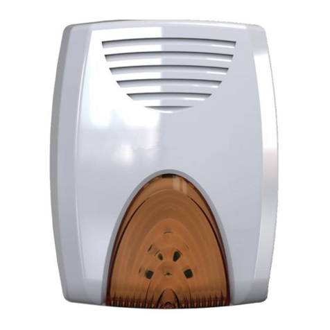
Tecnoalarm SAEL 2010 BUS User manual

SAEL 2010 BUS Rel. 2.2 - 08/2016
1
A A
2
B
BB
B
C
+
-
AB
1
2
3
4
3
D D
E E
F
1
A A
2
B
BB
B
C
+
-
AB
1
2
3
4
3
D D
E E
F
SAEL 2010 BUS - Sirena autoalimentata SAEL 2010 BUS - Sirène autoalimentée
SCHEDA ELETTRONICA CARTE ÉLECTRONIQUE
21
ON
43
1 2 3 4 Adresse
OFF OFF OFF OFF Non valide
ON OFF OFF OFF Adresse 1
OFF ON OFF OFF Adresse 2
ON ON OFF OFF Adresse 3
OFF OFF ON OFF Adresse 4
ON OFF ON OFF Adresse 5
OFF ON ON OFF Adresse 6
ON ON ON OFF Adresse 7
OFF OFF OFF ON Adresse 8
ON OFF OFF ON Adresse 9
OFF ON OFF ON Adresse 10
ON ON OFF ON Adresse 11
OFF OFF ON ON Adresse 12
ON OFF ON ON Adresse 13
OFF ON ON ON Adresse 14
ON ON ON ON Adresse 15
5
ON 5 Baud rate
OFF 9.600bps
ON 38.400bps
6
ON 6 Signalisation système en service
OFF Habilité
ON Déshabilité
Cavalier terminaison ligne sérielle
JP1 Insérer sur le dernier dispositif de la ligne sérielle.
LED Couleur Signalisation
Power Verte Allumée Alimentation OK
Éteinte Alimentation KO
Run Jaune Clignotante Fonctionnement OK
Éteinte/Allumée Fonctionnement KO
21
ON
43
1 2 3 4 Indirizzo
OFF OFF OFF OFF Non valido
ON OFF OFF OFF Indirizzo 1
OFF ON OFF OFF Indirizzo 2
ON ON OFF OFF Indirizzo 3
OFF OFF ON OFF Indirizzo 4
ON OFF ON OFF Indirizzo 5
OFF ON ON OFF Indirizzo 6
ON ON ON OFF Indirizzo 7
OFF OFF OFF ON Indirizzo 8
ON OFF OFF ON Indirizzo 9
OFF ON OFF ON Indirizzo 10
ON ON OFF ON Indirizzo 11
OFF OFF ON ON Indirizzo 12
ON OFF ON ON Indirizzo 13
OFF ON ON ON Indirizzo 14
ON ON ON ON Indirizzo 15
5
ON 5 Baud rate
OFF 9.600bps
ON 38.400bps
6
ON 6 Segnalazione sistema inserito
OFF Abilitato
ON Disabilitato
Ponticello terminazione linea seriale
JP1 Inserire sull’ultimo dispositivo della linea seriale.
LED Colore Segnalazioni
Power Verde Acceso Alimentazione OK
Spento Alimentazione KO
Run Giallo Lampeggiante Funzionamento OK
Spento/Acceso Funzionamento KO
INSTALLAZIONE INSTALLATION
+
-
AB
1
2
3
4
4B Canal B ligne sérielle
3A Canal A ligne sérielle
2- Négatif d’alimentation
1+ Positif d’alimentation
1 - Ouverture du boîtier
Enlever le couvercle de la sirène en desserant les deux vis (A).
2 - Fixation au mur
Fixer le fond du boîtier sur une surface solide en utilisant les
trous de fixation (B).
Fixation du contact d’auto-surveillance
Décliqueter le contact d’auto-protection. À l’aide de la
cheville incluse, fixer le rectangle en plastique (C) au mur en
faisant attention à ne pas l’arracher du fond du boîtier, puis
encliqueter de nouveau le contact d’auto-protection.
Le contact d’auto-protection protège soit contre
l’arrachement du mur soit contre l’ouverture du boîtier.
N.B. Ne jamais enlever le rectangle de plastique du fond du boîtier.
3 - Raccordement
Placer la batterie avec les bornes de connexion pointant
vers le haut dans son emplacement (D) en faisant passer les
câbles de connexion rouge et noir derrière elle. Accrocher la
batterie et embrocher les cosses faston (E) des câbles rouge
et noir sur les bornes.
Effectuer le raccordement électrique de la sirène en utilisant
le bornier (F).
Replacer le couvercle et revisser les deux vis.
+
-
AB
1
2
3
4
4B Canale B linea seriale
3A Canale A linea seriale
2- Negativo di alimentazione
1+ Positivo di alimentazione
1 - Apertura del contenitore
Rimuovere il coperchio svitando le due viti frontali (A).
2 - Fissaggio a muro
Fissare la base su una superficie rigida utilizzando le asole
per il fissaggio (B).
Montaggio del contatto tamper
Sganciare l’interruttore di autoprotezione. Utilizzando
il tassello dato in dotazione fissare il rettangolo di plastica
(C) alla parete avendo cura di non staccarlo dal fondo del
contenitore, quindi riagganciare l’interruttore
di autoprotezione. Il contatto tamper ha le funzioni
di antistrappo dal muro e antiapertura del contenitore.
N.B. Non rimuovere il rettangolo di plastica dal fondo del
contenitore.
3 - Collegamento
Inserire la batteria con i terminali di collegamento verso
l’alto nell’apposito spazio (D) facendo passare i cavi di
collegamento rosso e nero dietro la batteria. Bloccare la
batteria utilizzando i ganci (E) poi collegare i terminali della
batteria ai cavi rosso e nero.
Effettuare il collegamento elettrico della sirena utilizzando la
morsettiera (F).
Riposizionare il coperchio della sirena ed avvitare le due viti.
CARATTERISTICHE TECNICHE E FUNZIONI - CARACTÉRISTIQUES TECHNIQUES ET FONCTIONS - TECHNICAL AND FUNCTIONAL SPECIFICATIONS - CARACTERÍSTICAS TÉCNICAS Y FUNCIONES - TECHNISCHE DATEN UND FUNKTIONEN
CARATTERISTICHE ACUSTICHE CARACTÉRISTIQUES ACOUSTIQUES ACOUSTIC SPECIFICATIONS CARACTERÍSTICAS ACÚSTICAS AKUSTISCHE EIGENSCHAFTEN
Pressione acustica Pression sonore Sound level Potencia acústica Schalldruck >103dB(A) @ 1m
Frequenza di funzionamento programmabile Fréquence programmable Frequency programmable Frecuencia de funcionamiento programable Betriebsfrequenz programmierbar ✓
Tempo massimo di suonata programmabile Temps maximum de sonnerie programmable Max. sound time programmable Tiempo máx. de sonido programable Max. Signalzeit programmierbar ✓
CARATTERISTICHE OTTICHE CARACTÉRISTIQUES OPTIQUES OPTICAL SPECIFICATIONS CARACTERÍSTICAS ÓPTICAS AKUSTISCHE EIGENSCHAFTEN
Lampeggiante Clignotant Flashlight Destellante Blinklicht LED
Colore lampeggiate Couleur clignotant Color flashlight Color destellante Farbe Blinklicht Orange
Frequenza di lampeggio programmabile Fréquence de clignotement programmable Flash rate Frecuencia de destello programable Blikfrquenz programmierbar ✓
ALIMENTAZIONE ALIMENTATION POWER SUPPLY ALIMENTACIÓN STROMVERSORGUNG
Tensione nominale Tension nominale Rated voltage Tensión nominal Nennspannung 12V DC
Tensione di alimentazione Tension d’alimentation Operating voltage Tensión de trabajo Betriebsspannung 10.5…14.5V DC
Tensione di ricarica batteria Tension de recharge batterie Battery recharge voltage Tensión de recarga batería Batterieladespannung 14.4V DC
CONSUMO CONSOMMATION CONSUMPTION CONSUMO STROMAUFNAHME
A riposo Au repos Stand-by En reposo Ruhezustand 8mA
In allarme (lampeggiante + sirena) En alarme (clignotant + sirène) Alarm En alarma Alarm 1.8A
In segnalazione LED En signalisation de LED LED signaling consumption En señalización de LED Bei LED-Signalgebung 70 mA
AUTO-PROTEZIONI AUTO-SURVEILLANCE TAMPER PROTECCIÓN DE TAMPER SABOTAGESCHUTZ
Antiapertura/rimozione Anti-ouverture et anti-arrachement Anti-opening and anti-detachment Antiaperura y antiarranque Öffnungs- und Abhebeschutz Micro-switch
Antischiuma ottico Antimousse optique Optical antifoam protection Protección antiespuma óptica Optischer Ausschäumschutz ✓
CARATTERISTICHE FISICHE CARACTÉRISTIQUES PHYSIQUES PHYSICAL SPECIFICATIONS CARACTERÍSTICAS FÍSICAS PHYSIKALISCHE EIGENSCHAFTEN
Alloggiamento batteria Batterie Battery Batería Batterie 12V/2.1Ah
Temperatura di funzionamento Température de fonctionnement Operating temperature Temperatura de funcionamiento Betriebstemperatur -40°C ... +50°C
Grado di protezione Indice de protection Protection class Clase de protección Schutzklasse IP44-IK08
Classe ambientale Classe environnementale Environmental class Clase ambiental Umweltklasse IIIA (EN 50131-5)
Contenitore Boîtier Casing Caja Gehäuse ABS / Al
Dimensioni (L xAx P) Dimensions (L x H x P) Dimensions (L x H x D) Dimensiones (L xAx P) Abmessungen (L x H x B) 211 x 315 x 98mm
Peso (senza batteria) Poids (sans batterie) Weight (without battery) Peso (sin batería) Gewicht 2Kg (ABS) - 2.7Kg (Al)
CONFORMITÀ CONFORMITÉ CONFORMITY CONFORMIDAD KONFORMITÄT
Norma Norme Norm Norma Norm EN 50131-4
Grado di sicurezza Niveau de sécurité Security grade Grado de seguridad Sicherheitsgrad 3
N.B. La dichiarazione di conformità è disponibile sul sito www.tecnoalarm.com / N.B. La déclaration de conformité est disponible sur le site web: www.tecnoalarm.com / N.B. The declaration of conformity is available on the website: www.tecnoalarm.com
N.B. La declaración de conformidad está disponible a la página web: www.tecnoalarm.com / N.B. Die Konformitätserklärung steht auf folgender Webseite zur Verfügung: www.tecnoalarm.com
DESCRIZIONE DESCRIPTION
La SAEL 2010 BUS è una sirena con lampeggiante
a LED e con tecnologia RSC®. Il modo di funzionamento
è programmabile come sirena interna o sirena esterna.
La sirena è disponibile con diversi contenitori:
• ABS grigio (cod. art. F105S2010BUSGR)
• Alluminio (cod. art. F105S2010BUSAL)
• Alluminio cromato (cod. art. F105S2010BUSCR)
Test di funzionamento
Ogni 18h o all’inserimento di 1 programma associato, la sirena
esegue automaticamente il test della tromba e della batteria.
La SAEL 2010 BUS est une sirène avec clignotant à
LED et avec technologie RSC®. Le fonctionnement est
programmable comme sirène d’intérieur ou d’extérieur.
La sirène est disponible avec divers boîtiers:
• En ABS gris (no.art. F105S2010BUSGR)
• En alluminium (no.art. F105S2010BUSAL)
• En alluminium chromé (no.art. F105S2010BUSCR)
Test de fonctionnement
Toutes les 18h ou à la MES d’un programme associé,
la sirène effectue le test de la cloche et de la batterie.
Compatibilità
TP8-28 - TP8-28 GSM ver. 0.2.00 TP10-42 ver. 1.5.14 TP8-88 ver. 0.8.08
TP20-440 ver. 1.2.08 Moduli SPEED PLUS ver. 1.9.05 Software Tecnoalarm ver. 4.4.2
Compatibilité
TP8-28 - TP8-28 GSM ver. 0.2.00 TP10-42 ver. 1.5.14 TP8-88 ver. 0.8.08
TP20-440 ver. 1.2.08 Modules SPEED PLUS ver. 1.9.05 Logiciel Tecnoalarm ver. 4.4.2

SAEL 2010 BUS Rel. 2.2 - 08/2016
21ISTR07412
Via Ciriè 38 - 10099 San Mauro T.se - Torino (Italy)
tel +390112235410 - fax +390112735590
tecnoalarm@ tecnoalarm.com
www.tecnoalarm.com
Lead free
compliant
RoHS
Pb
Pb
Le caratteristiche del prodotto possono essere soggette a modifiche senza alcun preavviso.
Les caractéristiques de ce produit peuvent être sujettes à modifications sans préavis.
The product features can be subject to change without notice.
Las funciones del producto pueden estar sujetas a modificaciones sin previo aviso.
Die Charakteristika des Produktes können jederzeit ohne vorherige Ankündigung geändert werden.
1
A A
2
B
BB
B
C
+
-
AB
1
2
3
4
3
D D
E E
F
1
A A
2
B
BB
B
C
+
-
AB
1
2
3
4
3
D D
E E
F
1
A A
2
B
BB
B
C
+
-
AB
1
2
3
4
3
D D
E E
F
SAEL 2010 BUS - Selbstgespeiste SireneSAEL 2010 BUS - Sirena autoalimentadaSAEL 2010 BUS - Self-powered siren
The SAEL 2010 BUS is a siren with LED flashlight and with RSC®technology.
The functioning mode is programmable as indoor or outdoor siren.
The siren is available with various casings:
• Gray ABS casing (item no. F105S2010BUSGR)
• Aluminum casing (item no. F105S2010BUSAL)
• Chrome-plated aluminum casing (item no. F105S2010BUSCR).
Functioning test
Every 18h or on arming of an associated program, the siren automatically checks
functioning of the horn and the battery.
La SAEL 2010 BUS es una sirena con destellante a LED y con tecnología RSC®.
El funcionamiento se puede programar como sirena para interior o exterior.
La sirena está disponible con varias cajas:
• Caja de ABS gris (cód.art. F105S2010BUSGR)
• Caja de aluminio (cód.art. F105S2010BUSAL)
• Caja de aluminio cromada (cód.art. F105S2010BUSCR).
Test de funcionamiento
Cada 18h o al conectar un programa asociado, la sirena ejecuta automáticamente
el test de la bocina y de la batería.
Die SAEL 2010 BUS ist eine Sirene mit LED-Blinklicht und mit RSC®-Technologie.
Die Funktionsweise ist als Innen- oder Außensirene programmierbar.
Die Sirene ist in verschiedenen Ausführungen erhältlich:
• Graues ABS-Gehäuse (Art.-Nr. F105S2010BUSGR)
• Aluminiumgehäuse (Art.-Nr. F105S2010BUSAL)
• Verchromtes Aluminiumgehäuse (Art.-Nr. F105S2010BUSCR).
Funktionstest
Alle 18h oder bei der Scharfschaltung eines zugeordneten Programms führt die
Sirene automatisch den Test des Signalhorns und der Batterie durch.
DESCRIPTION DESCRIPCIÓN BESCHREIBUNG
ELECTRONIC BOARD PLACA ELECTRÓNICA PLATINE
1 2 3 4 Address
21
ON
43
OFF OFF OFF OFF Not valid
ON OFF OFF OFF Address 1
OFF ON OFF OFF Address 2
ON ON OFF OFF Address 3
OFF OFF ON OFF Address 4
ON OFF ON OFF Address 5
OFF ON ON OFF Address 6
ON ON ON OFF Address 7
OFF OFF OFF ON Address 8
ON OFF OFF ON Address 9
OFF ON OFF ON Address 10
ON ON OFF ON Address 11
OFF OFF ON ON Address 12
ON OFF ON ON Address 13
OFF ON ON ON Address 14
ON ON ON ON Address 15
5
ON 5 Baud rate
OFF 9,600bps
ON 38,400bps
6
ON 6 Armed system signal
OFF Enabled
ON Disabled
1 2 3 4 Dirección
21
ON
43
OFF OFF OFF OFF No válida
ON OFF OFF OFF Dirección 1
OFF ON OFF OFF Dirección 2
ON ON OFF OFF Dirección 3
OFF OFF ON OFF Dirección 4
ON OFF ON OFF Dirección 5
OFF ON ON OFF Dirección 6
ON ON ON OFF Dirección 7
OFF OFF OFF ON Dirección 8
ON OFF OFF ON Dirección 9
OFF ON OFF ON Dirección 10
ON ON OFF ON Dirección 11
OFF OFF ON ON Dirección 12
ON OFF ON ON Dirección 13
OFF ON ON ON Dirección 14
ON ON ON ON Dirección 15
5
ON 5 Baud rate
OFF 9.600bps
ON 38.400bps
6
ON 6 Señalización sistema conectado
OFF Habilitado
ON Deshabilitado
21
ON
43
1 2 3 4 Adresse
OFF OFF OFF OFF Ungültig
ON OFF OFF OFF Adresse 1
OFF ON OFF OFF Adresse 2
ON ON OFF OFF Adresse 3
OFF OFF ON OFF Adresse 4
ON OFF ON OFF Adresse 5
OFF ON ON OFF Adresse 6
ON ON ON OFF Adresse 7
OFF OFF OFF ON Adresse 8
ON OFF OFF ON Adresse 9
OFF ON OFF ON Adresse 10
ON ON OFF ON Adresse 11
OFF OFF ON ON Adresse 12
ON OFF ON ON Adresse 13
OFF ON ON ON Adresse 14
ON ON ON ON Adresse 15
5
ON 5 Baud rate
OFF 9.600bps
ON 38.400bps
6
ON 6 Signal für sharfes System
OFF Aktiv
ON Deaktiviert
Jumper end-of serial bus
JP1 Inserted on the last device of the serial line.
Puente fin de línea serial
JP1 Conectado en el último dispositivo de la línea serial.
Bus-Termination-Jumper
JP1 Auf dem letzten Gerät der Schnittstelle stecken.
LED Color Signaling
Power Green On Power supply OK
Off Power supply KO
Run Yellow Blinking Functioning OK
Off/On Functioning KO
LED Color Señalizaciones
Power Verde Encendido Alimentación OK
Apagado Alimentación KO
Run Amarillo Parpadeante Funcionamiento OK
Apagado/Encendido Funcionamiento KO
LED Farbe Signalgebung
Power Grün An Stromversorgung OK
Aus Stromversorgung KO
Run Gelb Blinkt Funktionsfähig OK
Aus/An Funktionsfähig KO
INSTALACIÓN INSTALLATION
INSTALLATION
1 - Opening of the casing
Release the 2 screws (A) on the siren
cover and remove the cover.
2 - Wall fixing
Fix the bottom of the casing to a solid
surface using the mounting holes (B).
Fixing of the tamper switch
Unblock the tamper switch. With the help
of the included dowel, fix the plastic
rectangle (C) to the wall paying attention
not to break it off the bottom of the
casing. Then engage the tamper switch
again. The tamper switch protects both
against the detachment of the siren from
the wall and opening of the casing.
N.B. Never remove the plastic rectangle
from the bottom of the casing.
3 - Connection
Place the battery with the connection
terminals upwards into its bay (D)
passing the red and black connection
cables behind it. Block the battery and
plug the faston connectors (E) of the red
and black cables in the terminals.
Make the electrical connection of the
siren using the terminals (F).
Replace the cover of the siren and
tighten the two screws.
+
-
AB
1
2
3
4
4B Channel B serial bus
3A Channel A serial bus
2- Negative power supply
1+ Positive power supply
1 - Apertura de la caja
Destornille los 2 tornillos (A) en la tapa
de la sirena y sacar la tapa.
2 - Montaje en la pared
Fije la base de la carcasa en una
superfice estable en correspondencia de
los ojales (B).
Montaje del contacto tamper
Desenganche el contacto de tamper.
Con la ayuda de la clavija incluida, fije
el rectángulo de plástico (C) en la pared
guidando a no sacarlo del fondo de la
caja. Después enganche el contacto de
tamper de nuevo. El contacto de tamper
protege tanto del arranque de la sirena
de la pared como de la apertura de la
caja.
N.B. Nunca saque el rectángulo de
plástico en el fondo de la caja.
3 - Conexión
Instale la batería con los bornes hacia
arriba en su emplazamiento (D) pasando
los cables de conexión rojo y negro
por detras de ella. Bloquee la batería y
enchufar los conectores faston (E) de los
cables rojo y negro en los bornes.
Efectúe la conexión eléctrica de la sirena
utilizando los bornes (F).
Vuelva a colocar la tapa de la sirena y
atornille los dos tornillos.
+
-
AB
1
2
3
4
4B Canal B línea serial
3A Canal A línea serial
2- Negativo de alimentación
1+ Positivo de alimentación
1 - Öffnen des Gehäuses
Die beiden Schrauben (A) auf dem
Deckel der Sirene lösen und den Deckel
abheben.
2 - Befestigung
Die beigefügten Unterlegscheiben auf
die vier Montageöffnungen legen und
den Boden des Gehäuses an der Wand
befestigen (B).
Montage des Sabotagekontaktes
Den Sabotagekontakt aushaken. Mit Hilfe
des beigefügten Dübels das Plastikrechteck
(C) an der Wand befestigen, ohne es aus
dem Gehäuseboden herauszubrechen.
Danach den Sabotagekontakt wieder
einhaken. Der Sabotagekontakt schützt
sowohl gegen das Abheben der Sirene
von der Wand als auch gegen das
Öffnen des Gehäuses.
N.B. Montieren Sie das Plastikrechteck
an der Wand ohne es vom Boden des
Gehäuses zu lösen.
4 - Verbindung
Die Batterie mit den Klemmen nach oben
in den dafür vorgesehenen Platz (D)
einsetzen und das rote und das schwarze
Verbindungskabel hinter der Batterie
vorbeiführen. Die Batterie arretieren und
die Faston-Verbindungsstecker (E) des
roten und des schwarzen Verbindungs-
kabels auf die Klemmen stecken. Stellen
Sie die elektrische Verbindungs der
Sirene mit dem System her (F).
Den Deckel schließen und die beiden
Schrauben festziehen.
+
-
AB
1
2
3
4
4B Kanal B Schnittstelle
3A Kanal A Schnittstelle
2-
Neg. Versorgungsspan
nung
1+
Pos. Versorgungsspan
nung
Compatibility
TP8-28 - TP8-28 GSM rel. 0.2.00 TP10-42 rel. 1.5.14 TP8-88 rel. 0.8.08
TP20-440 rel. 1.2.08 SPEED PLUS modules rel. 1.9.05 Tecnoalarm Software rel. 4.4.2
Compatibildad
TP8-28 - TP8-28 GSM ver. 0.2.00 TP10-42 ver. 1.5.14 TP8-88 ver. 0.8.08
TP20-440 ver. 1.2.08 Módulos SPEED PLUS ver. 1.9.05 Software Tecnoalarm ver. 4.4.2
Kompatibilität
TP8-28 - TP8-28 GSM Ver. 0.2.00 TP10-42 Ver. 1.5.14 TP8-88 Ver. 0.8.08
TP20-440 Ver. 1.2.08 SPEED PLUS Module Ver. 1.9.05 Tecnoalarm Software Ver. 4.4.2
Other Tecnoalarm Security System manuals
Tecnoalarm
Tecnoalarm EV REDWAVE BWL User manual
Tecnoalarm
Tecnoalarm SIRTEC BUS User manual
Tecnoalarm
Tecnoalarm SAEL 2010 LED User manual

Tecnoalarm
Tecnoalarm TWINTEC MASK BUS User manual
Tecnoalarm
Tecnoalarm Evolution EV SAEL BWL User manual

Tecnoalarm
Tecnoalarm evolution EV SIREL BWL User manual
Tecnoalarm
Tecnoalarm TP8-64 User manual
Tecnoalarm
Tecnoalarm TWINTEC MASK 18 User manual
Popular Security System manuals by other brands

Smarti
Smarti SmartHome Installation and operating instructions
Thrane&Thrane
Thrane&Thrane SAILOR 6101 Installation and user manual
Aritech
Aritech CS-250 owner's manual
Britax
Britax BFR1000 Series Installation & operation manual

Gemini
Gemini 973AR Installation and use manual

GE
GE Security Pro 1000 user guide

