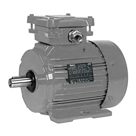
Tecnoautomazione TM4 Series User manual

ALIMENTAZIONE
ASSORBIMENTO
POTENZA
SPINTA MAX
GRADO IP
VELOCITÀ
TEMPO DI LAVORO
DIAMETRO
LUNGHEZZA CAVO
230 V
191 W
30 N
44
15 rpm
4 min
0,83 A
45 mm
1,8 m
0,86 A
198 W
40 N
44
45 mm
4 min
15 rpm
1,8 m
230 V
205 W
50 N
44
0,89 A
45 mm
4 min
12 rpm
1,8 m
230 V
40
TM4 50
TM4TM4 30
CARATTERISTICHE TECNICHE
Grado di protezione
Potenza
Assorbimento
Peso motore
Tempo di lavoro
Grado d’ isolamento
Modello motore
Diametro
2
Coppia
3
Velocità
Tensione
Frequenza
Non far entrare l’acqua all’interno del motore.
Non colpire / percuotere il motore e il tubo esterno.
Non esporre il motore ad acidi, fonti alcaline e corrosive.
Non sovraccaricare o utilizzare il motore in modo eccessivo,
questo potrebbe ridurne considerevolmente il suo ciclo di vita.
ATTENZIONE
4min
IP44
1.43kg
121W
50Hz
I.CI.H
0.53A
230V
Ø35
6N.m
35S-6/28
10
47 8 1112
2659
28r/min
Motore
tubolare
asincrono
monofase
Motore
Tubolare
1
3
A
B
CD
fine motore B = A - (C+D)
Fig.1
fine calotta
intaglio tubo
4×7.3
L
liguetta puleggia
posizione vite
centro dell’adattatore
Fig.2
PREPARAZIONE DEL TUBO
In base alla lunghezza B preparare il tubo esterno: B = A - (C+D)
A = Larghezza totale della finestra o della porta.
C = Spessore limite testa + spessore staffa del motore.
D = Spessore calotta regolabile + spessore staffa della calotta regolabile. (Vedi fig.1).
Nel caso si utilizzi un tubolare rotondo, la posizione della vite di fissaggio del adattatore
del tubolare esterno deve avere la misura (L) perforando due fori simmetrici per viti a testa
svasata M4. Nel frattempo perforare due fori per viti a testa svasata M4 nella posizione
adatta per fissare la calotta regolabile e il tubo esterno. (Vedi fig. 2).
Nel caso si utilizzi un tubo rotondo senza corona, aprire due fessure sull'estremità del tubolare
in modo da farlo coincidere con le linguette a gancio della puleggia del motore. Le dimensioni
delle fessure dipendono dalle linguette di ogni motore.
I tubi ottagonali non necessitano di fori sul tubo esterno.
Rimuovere tutte le sbavature dopo il taglio del tubolare.
linguetta puleggia
corona
adattatore
molletta
ASSEMBLAGGIO DEGLI ACCESSORI
1. Infilare la corona sul corpo del motore in modo da poterla collegare
alla puleggia del motore. Inserire l'adattatore usando la molletta per
fissarlo all'albero esterno.
2. Inserire il motore nel tubolare esterno con la calotta regolabile.
3. Montare il limite testa da una parte
e la calotta regolabile dall'altra con le
loro rispettive staffe.
ATTENZIONE non perforare
tra la corona e l'ingranaggio.
staffa a muro
staffa motore
corona
adattatore molletta
calotta regolabile staffa calotta
regolabile
staffa
a muro
adattatore
tubolare esterno
calotta regolabile
Impostazione fine corsa in alto: Trimmer bianco
Impostazione fine corsa in basso: Trimmer rosso
posizione desiderata
posizione corrente
posizione corrente
posizione desiderata
posizione desiderata
posizione corrente
posizione corrente
posizione desiderata Premere il pulsante
di comando in alto per
avvicinarsi alla posizione
desiderata
Premere il pulsante
del telecomando in
basso per superare
la posizione desiderata fino a superare la
posizione desiderata
Avvitare
fino a superare la
posizione desiderata
Avvitare
Premere il bottone in alto
Premere il bottone in basso
Premere il pulsante
del telecomando in
basso per chiudere fino
alla posizione desiderata
Premere il pulsante
del telecomando in
alto per superare la
posizione desiderata
Avvitare
Avvitare
fino alla
posizione
desiderata
Avvitare
fino alla
posizione
desiderata
Avvitare impostazione
completata
AC 230V/50HZ Nero = fase 1
Blu = neutro
Marrone = fase 2
Giallo / Verde = terra
AC 120V/60HZ Nero = fase 2
Rosso = fase 1
Bianco = neutro
Verde = terra
N
L
PE
aperto/chiuso su/giù
blu
nero
marrone
verde
giallo
CONNESSIONE CAVI - AC 230V/50Hz RISOLUZIONE PROBLEMI
PROBLEMA CAUSE DEL MALFUNZIONAMENTO SOLUZIONI E SUGGERIMENTI
1
3
4
Premendo il pulsante in alto del telecomando,
la tapparella si abbassa La connessione dei cavi è errata Invertire la posizione dei cavi nero e marrone
2All' accensione il motore si muove
solo in una direzione ll fine corsa non permette l'apertura Ruotare uno dei trimmer 1-2 cicli nel
senso opposto
All' accensione il motore non funziona
o funziona in rallentamento
L'alimentazione non è conforme alla tensione
Sovraccarico
L’errata istallazione degli accessori interni
blocca il motore
I finecorsa non sono regolati
Cambiare il motore in base all' alimentazione
Cambiare il motore in base alla portata in Nm
Controllare la corretta installazione dei componenti
Ruotare uno dei trimmer in qualsiasi direzione
Il motore si ferma improvvisamente
Il motore è surriscaldato
Mancanza di rete elettrica
Il motore ha raggiunto il limite
Raffreddare il motore per circa 20 minuti
Ripristinare la connessione alla rete elettrica
Verificare se bisogna regolare il fine corsa
Rumore anomalo durante il funzionamento Il tubolare esterno è troppo lungo e causa
una pressione stretta sulle staffe
Se la calotta regolabile è inserita tagliare un
piccolo pezzo di tubo esterno
4
5
Motore Tubolare TM4 SERIES con finecorsa meccanico - alimentazione 230 V Italiano
corona
IMPOSTAZIONE DEL FINECORSA
impostazione
completata
fino alla
posizione
desiderata
fino alla
posizione
desiderata
impostazione
completata
impostazione
completata

230 V
191 W
30 N
44
15 rpm
4 min
0,83 A
45 mm
1,8 m
0,86 A
198 W
40 N
44
45 mm
4 min
15 rpm
1,8 m
230 V
205 W
50 N
44
0,89 A
45 mm
4 min
12 rpm
1,8 m
230 V
40
TM4 50
TM4TM4 30
IP level
Motor weight
Running time
Insulation degree
Motor mode
Tube diameter
2
Rated torque
3
Rated speed
Rated voltage
Rated frequency
4min
IP44
1.43kg
121W
50Hz
I.CI.H
0.53A
230V
Ø35
6N.m
35S-6/28
10
47 8 1112
2659
28r/min
Tubolar single
phase
asynchronous
motor
Tubolar
Motor
1
3
Tubolar Motor TM4 SERIES with mechanical limit switch - power supply 230 V English
TECHNICAL FEATURES
POWER SUPPLY
ABSORPTION
MOTOR POWER
MAXIMUM THRUST
IP LEVEL
RATED SPEED
RUNNING TIME
TUBE DIAMETER
CABLE LENGTH
ATTENTION
Do not let water penetrate into the motor.
Do not Strike, hit the motor and the outer tube.
Do not start the motor excessively or overload it
as it might reduce its lifespan.
Do not store the motor with strong acid, alkali or
dirty and eroding materials.
Rated power
Rated current
target position
current position
current position
target position
target position
current position
current position
taget position
until exceed
target position
Screw
Screw
Press upward key
Press downard key
Press downward
key until close to
target position
Press upward
key run until
exceed
target position
Screw
Screw
AC 230V/50HZ Black = phase 1
Blue = neutral
Brown = phase 2
Yellow / Green = ground
AC 120V/60HZ Black = phase 2
Red = phase 1
White = neutral
Green = ground
N
L
PE
open/close
up/down
blue
black
brown
green
yellow
WIRE CONNECTIONS - AC 230V/50Hz TROUBLE SHOOTING
TROUBLE THE CAUSE OF THE MALFUNCTION SOLUTION AND SUGGESTIONS
1
3
4
The wire connection is wrong Invert the position of the black and brown wires
2
Overload
Both limit switches don't open
Check the correct installation of the internal parts
Motor stop suddenly after running
The motor is overheated
Power cut off
Reaching the limits
Cool the motor for about 20 minutes
Restart after connecting the power
Check if an adjustment of the limits is needed
Abnormal sound during working
4
5
LIMITS SETTINGS
Upper position set up: White trimmer
Lower position set up: Red trimmer
Press upward
key run near
target position
until to
target
position
until to
target
position
Screw
until to
target
position
Press downward
key run until
exceed target
position
set up is OK
set up is OK
set up is OK
set up is OK
until the
target position
Screw
until exceed
target position
When pressing the upward button of the
controller, the shutter moves downward
When switched on the motor runs in
one-way direction only
The motor's limit switch doesn't
allow the opening Rotate one of the trimmers 1-2 rotations
in the opposite direction
The power supply doesn't conform to
the rated voltage
Improper installation of the internal
parts makes the motor get stuck
When switched on the motor doesn't work
or works slowly
Change the motor in accordance with the
rated power supply
Use the correct motor in accordance with its
range in Nm
Rotate one of the trimmers in any direction
The outer tube is too long, which causes a
tight pressure on both brackets If the idler is used, cut the outer tube a little bit
T.A. Tecno Automazione s.r.l. - Via Vicinale snc - 03018 - Paliano - (FR) - Italy - Tel +39 0775 533677 - Fax +39 0775 533299 - [email protected] - www.tecnoautomation.com - www.tecnoautomazione.com
A) Dichiarazione per AEE Domesche senza Pile o Accumulatori portali
INFORMAZIONE AGLI UTENTI DI APPARECCHIATURE DOMESTICHE O PROFESSIONALI
Ai sensi dell'art. 26 del Decreto Legislavo 14 marzo 2014, n. 49 "Auazione della Direva 2012/19/UE sui rifiu di apparecchiature eleriche ed eleroniche (RAEE)"
Il simbolo del cassoneo barrato riportato sull'apparecchiatura o sulla sua confezione indica che il prodoo alla fine della propria vita ule deve essere raccolto separatamente dagli altri rifiu per permeerne un adeguato traamento e
riciclo. L'utente dovrà, pertanto, conferire gratuitamente l'apparecchiatura giunta a fine vita agli idonei centri comunali di raccolta differenziata dei rifiu elerici ed eleronici, oppure riconsegnarla al rivenditore secondo le seguen
modalità: - per apparecchiature di piccolissime dimensioni, ovvero con almeno un lato esterno non superiore a 25 cm, è prevista la consegna gratuita senza obbligo di acquisto presso i negozi con una superficie di vendita delle
apparecchiature eleriche ed eleroniche superiore ai 400 mq. Per negozi con dimensioni inferiori, tale modalità è facoltava.
- per apparecchiature con dimensioni superiori a 25 cm, è prevista la consegna in tu i pun di vendita in modalità 1contro1, ovvero la consegna al rivenditore potrà avvenire solo all'ao dell'acquisto di un nuovo prodoo equivalente, in
ragione di uno a uno. L'adeguata raccolta differenziata per l'avvio successivo dell'apparecchiatura dismessa al riciclaggio, al traamento e allo smalmento ambientalmente compabile contribuisce ad evitare possibili effe negavi
sull'ambiente e sulla salute e favorisce il reimpiego e/o riciclo dei materiali di cui è composta l'apparecchiatura. Lo smalmento abusivo del prodoo da parte dell'utente comporta l'applicazione delle sanzioni di cui alla corrente normava
di legge. Tecno Automazione ha scelto di aderire a Consorzio Remedia, un primario Sistema Collevo che garansce ai consumatori il correo traamento e recupero dei RAEE e la promozione di poliche orientate alla tutela
ambientale.
and ask for the correct method of disposal.
informaon. For disposal in countries outside of the European Union This symbol is only valid in the European Union (EU). If you wish to discard this product please contact your local authories ordealer
For private households: Informaon on Disposal for Users of WEEE This symbol on the product(s) and / or accompanying documents means that used electrical and electronicequipment (WEEE) should not be mixed with general
household waste. For proper treatment, recovery and recycling, please take this product(s) to designated collecon points where it will be accepted free of charge. Alternavely, in some countries, you may be able to return your
products to your local retailer upon purchase of an equivalent new product. Disposing of this product correctly will help save valuable resources and prevent any potenal negave effects on human health and the environment,
which could otherwise arise from inappropriate waste handling. Please contact your local authority for further details of your nearest designated collecon point. Penales may be applicable for incorrect disposal of this waste, in
accordance with you naonal legislaon. For professional users in the European Union If you wish to discard electrical and electronic equipment (EEE), please contact your dealer or supplier for further
raised key
crown
drive adapter
clip
1. Fit the crown to the motor's body making sure it is able to work with
the Raised key. Assemble the drive adapter and use the clip to lock it
to the outer shaft.
2. Assemble the outer tube and the idler.
3. The limit head should be assembled
to the motor bracket. The idler should
be assembled to the idler bracket.
wall bracket
motor bracket
crown
drive adapter clip
idler idler bracket
wall bracket
crown
drive adapter
outer tube
idler
ACCESSORIES ASSEMBLY
ATTENTION do not drill the
holes between the crown
and the gear ring..
This manual suits for next models
3
Other Tecnoautomazione Engine manuals
