CRD CONTROL UNITS FOR GAS AND FIRE DETECTION REV.1 072022
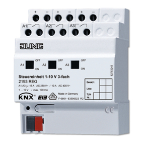
TECNOGAS CRD control units are produced in 4 versions:
• CRD/1 with one zone in 3 DIN module box
• CRD/2 with two zones in 3 DIN modules box
• CRD/3 with three zones in 6 DIN modules box
• CRD/4 with four zones in 6 DIN modules box
TECHNICAL FEATURES CRD 1-2 CRD 3-4
Power supply (see specifications below) 230 Vac - 12 Vac - 12 Vdc
Sensor lines voltage 12 Vdc 12 Vdc
Number of lines 1-2 3-4
Smoke sensors per line Max 10 Max 10
Gas detectors per line Max 1 Max 1
Load limitations 0.6 A 1.1 A
Alarm relay C NO NC 10 A 1 1
Acoustic signal at 1 m 10 db a 12 V a 30 cm
Alarm LED (red) 2 4
Detector fault LED (yellow) 2 4
Power LED (green) 1 1
System failure LED (yellow) 1 1
End of line resistance* 3300 Ω 3300 Ω
*Included in the box
WARNING!
THE INSTALLATION OF THE GAS DETECTOR DOES NOT EXEMPT
FROM THE OBSERVATION OF ALL THE RULES REGARDING
THE CHARACTERISTICS, THE INSTALLATION AND USE OF THE
GAS APPLIANCES, THE VENTILATION OF THE ROOMS AND THE
DISCHARGE OF THE COMBUSTION PRODUCTS PRESCRIBED BY
THE REGULATIONS AND LAWS IN FORCE.
The CRD/1-2-3-4 control units are designed to
be housed in a DIN bar. They can manage remote
detectors for gas detection (methane [CH4] and
LPG) or for fire.
They are extremely reliable and easy to use and
install.
The CRD control units can be used with remote
gas detectors produced by TECNOGAS (RMP) or
with any 4÷20 mA sensor.
The CRD control units work with a power
supply voltage of:
• 230 Vac with internal stabilized power
supply, protected against short-circuits and
overloads;
• or 12 Vac (code 554411 - 554413 - 554416
and 554418) with external power supply;
• or 12 Vdc with external power supply
(exclusively for codes 554431- 554433 -
554436- 554438).
The CRD control units are managed by a
microcontroller. They have been designed to
snap action with a 4÷20 mA signal and allow the
connection of a remote gas detector or up to ten
smoke sensors per line.
They have an alarm relay, a buzzer and two LEDs
for visual signals:
• a green LED relating to the power supply
(POWER)
• a yellow system FAULT LED, in compliance with
the new European standards EN 50271.
The CRD control units have:
• visual reference signal for each connected
remote detector: red for ALARM and yellow for
FAULT
• an overcurrent protection circuit for the power
supplies of the remote detectors. This circuit
intervenes either on the pair of remote detectors
or on the single remote detector, according to the
type of control panel. For example: in the CRD/1
control unit the protection intervenes on the single
detector; in the CRD/2 control panel it intervenes
on the pair of remote detectors, etc.
Note for the installation of remote gas detectors
(detector for methane and LPG protected against
water splashes IP55): the gas detectors require
the connection of a 3.3 KΩ end-of-line resistor
between the + and S connections of the terminal
board supplied to the same; the latter will serve
to avoid a false sensor anomaly being reported.
See the diagram below and the remote gas
detector documentation. The same caution must
be observed if the remote detectors set up for the
chosen control panel model are not connected.
In this case, the end-of-line resistor will be
positioned between the + and S connections of
the terminal board of the control unit itself.
EXAMPLE:
4-zone control unit used with 3 zones (insert a
resistance also in the fourth zone).
Gas detection systems: if, following an alarm,
the gas concentration returns below the alarm
threshold, the CRD control units return to
normal working conditions (buzzer and relay
at rest) but the alarm signal that occurred
with relative ignition remains of the flashing
red LED.
On the front of the control units there are the reference visual signals for the control unit itself and for the connected detectors.
VISUAL SIGNALS
FUNCTIONAL DESCRIPTION
TECNOGAS srl - Viale L. Da Zara, 10 - 35020 Albignasego - Padova - Italy


