Banner ES-UA-5A User manual

Emergency Stop Safety Modules
Model ES-UA-5A for 12-24V dc/115V ac operation; Model ES-VA-5A for 12-24V dc/230V ac operation
Features
• Monitors one dual-channel normally closed Emergency Stop switch circuit for
a contact failure or wiring fault
• Four output switching channels for connection to control-reliable power interrupt
circuits
• Auto reset or monitored manual reset
• Design complies with standards UL 991, EN 418, and EN 954-1 (Category 4)
• For use in functional stop category 0 applications per NFPA 79 and
IEC/EN 60204-1
• 6 amp safety output contacts
• Plug-in terminal blocks
• 12-24V dc/115V ac or 12-24V dc/230V ac operation
• External Device Monitoring (one-channel EDM)
WARNING . . .
This Emergency Stop Safety Module is not a point-of-operation guarding device, as defined by OSHA regulations. It is
necessary to install point-of-operation guarding devices, such as safety light curtains and/or hard guards, to protect personnel
from hazardous machinery. Failure to install point-of-operation guards on hazardous machinery can result in a dangerous
condition which could lead to serious injury or death.
EMERGENCY STOP DEVICE
29YL

E-Stop Safety Module – Models ES-UA-5A and ES-VA-5A
Important... read this page before proceeding!
Banner Engineering Corp. has made every effort to provide complete application, installation, operation, and maintenance instructions.
In addition, any questions regarding the use or installation of this Banner Emergency Stop Safety Module should be directed to the
factory applications department at the telephone numbers or address shown on back cover.
The user shall ensure that all machine operators, maintenance personnel, electricians, and supervisors are thoroughly familiar with
and understand all instructions regarding the installation, maintenance, and use of this Emergency Stop Safety Module, and with the
machinery it controls.
The user and any personnel involved with the installation and use of this model Emergency Stop Safety Module must be thoroughly
familiar with all applicable ANSI/NFPA standards. The standards, listed below, directly address the use of emergency stop systems.
Banner Engineering Corp. makes no claim regarding a specific recommendation of any organization, the accuracy or effectiveness of any
information provided, or the appropriateness of the provided information for a specific application.
The user has the responsibility to ensure that all local, state, and national laws, rules, codes, and regulations relating to the use of this
Emergency Stop Safety Module in any particular application are satisfied. Extreme care is urged that all legal requirements have been
met and that all installation and maintenance instructions contained in this manual are followed.
U. S. Standards Applicable to Use of Emergency Stop Safety Modules
ANSI B11 Standards for Machine Tools “Safety Requirementsfor the Construction, CareandUse”
Available from: Safety Director
AMT – TheAssociation forManufacturing Technology
7901WestparkDrive
McLean, VA22102
Tel.:703-893-2900
NFPA 79 “ElectricalStandardfor Industrial Machinery(1997)”
Available from: NationalFireProtection Association
1BatterymarchPark,P.O. Box 9101
Quincy, MA 02269-9101
Tel.:800-344-3555
ANSI/RIAR15.06 “Safety RequirementsforIndustrial RobotsandRobotSystems”
Available from: Robotic Industries Association
900 Victors Way, P.O.Box3724
AnnArbor,MI 48106
Tel.:734-994-6088
European Standards Applicable to Use of Emergency Stop Safety Modules
ISO/TR 12100-1& -2 (EN 292-1 &-2) “Safety of Machinery– Basic Concepts, General PrinciplesforDesign
Part 1: Basic Terminology, Methodology,and
Part 2:Technical Principals andSpecifications”
EN954-1 “SafetyofMachines:Safety Related Parts ofControl Systems:Part1 General Principlesfor Design”
IEC/EN 60204-1 “ElectricalEquipment of Machines: Part 1:General Requirements”
Also,requesta type“C”standard foryour specificmachinery.
EN418 “Safety ofMachinery – EmergencyStopEquipment Functional Aspects, Principles forDesign”
Available from: Global Engineering Documents
15Inverness Way East
Englewood, CO 80112-5704
Tel.:800-854-7179

E-Stop Safety Module – Models ES-UA-5A and ES-VA-5A
Overview
The purpose of an Emergency Stop Safety Module (E-Stop Safety Module) is to increase
the control reliability of an emergency stop circuit. As indicated in Figures 2 and 3, the
models ES-UA-5A and ES-VA-5A E-Stop Safety Modules are designed to monitor a
1-channel or 2-channel E-stop switch. A 2-channel E-stop switch has two electrically
isolated contacts.
EN 954-1 Safety Categories
Both contacts of a 2-channel E-stop switch are monitored by the Safety Module. If either
input is short-circuited, the Safety Module cannot be reset, and the controlled machinery
cannot be restarted, following actuation of the E-stop switch. Two-channel E-stop
switches used with this Safety Module are suitable for Safety Category 4 applications, per
European Standard ISO 13849-1 (EN 954-1), of which Category 4 is the highest safety
category.
Use of a 1-channel E-stop switch provides no input redundancy, and no ability for the
Safety Module to monitor for input short circuits. One-channel E-stop switches used with
this Safety Module are generally suitable only for Safety Category 2 applications, per
ISO 13849-1 (EN 954-1).
IEC/EN 60204-1 and NFPA 79 Functional Stop Categories
In a functional Category 0 emergency stop circuit, the opening of either of the two E-stop
switch contacts (or the one contact, if configured to 1-channel) immediately removes
electrical power from the machine control elements, which react to stop hazardous
machine motion and/or other machine hazards. This redundancy of stopping control
offered by a two-pole E-stop switch is the first step towards control reliability in an
emergency stop circuit.
The output of the E-Stop Safety Module consists of four redundant output switching
channels, each of which is the series connection of two forced-guided relay contacts that
are internally monitored (K1 and K2 in Figures 4 and 5). If the Module detects a failure,
such as a welded output relay contact, all outputs are disabled and cannot be reset. The
four switching output circuits of the E-Stop Safety Module are rated for up to 250V ac at
up to 6 amps.
The E-Stop Safety Module also provides a necessary reset function. U.S. and
international standards require that a reset/restart routine be performed after returning the
E-stop switch to its closed-contact position. This prevents the controlled machinery from
restarting by simply closing the E-stop switch. The Module may also be configured for
automatic reset (see Figures 4 and 5). The automatic reset mode is useful for some
automated processes. However, when automatic reset is used, an alternate means
must be established to require a reset/restart routine after the E-stop switch is
returned to its closed contact position (see WARNING on page 8).
This E-Stop Safety Module complies with the following design standards:
UL 991 Tests for Safety Related Control Employing Solid-State Devices
EN 418 Emergency Stop Equipment—Functional Aspects, Principles for Design
EN 954-1 Safety of Machines: Safety Related Parts of Control Systems
Part 1: General Design Directives (Safety Category 4)
The Safety Module has indicators for input power, fault, and output relay contact status
(K1 and K2); see Figure 1. There are no adjustments and no user-serviceable parts. See
page 10 for information regarding repair service.
POWER
FAULT
CH 1
CH 2
S31
A1 A2 B1 B2
13 14 23 24
S32
Y30 Y31 Y32 Y35 51 52
S33
S11 S12 S21 S22
33 34 43 44
S32S34 S35
S34 S32 S35
S11 S12 S21 S22
S31 S32 S33
A1 A2 B1 B2
Y30 Y31 Y32
13 14 23 24
Y35 51 52
33 34 43 44
K2
K1
K1
K2
51 52
Figure 1. ES-UA-5A and ES-VA-5A
Status Indicators and Terminal
Locations

E-Stop Safety Module – Models ES-UA-5A and ES-VA-5A
E-Stop Switch Requirements
As shown in Figures 4, 5, and 6, the E-stop switch must provide contacts which are
closed when the switch is in the “armed” position. Once activated, the E-stop switch must
open its contacts and be returned to the closed-contact position only by a deliberate
action (such as twisting, pulling, or unlocking). The switch should be a “positive-opening
type,” as described by IEC 60947-5-1. A mechanical force applied to such a button (or
switch) is transmitted directly to the contacts, forcing them open. This ensures that the
switch contacts will open whenever the switch is activated.
NFPA 79 specifies the following additional Emergency Stop Actuator requirements:
• Emergency Stop push buttons shall be located at each operator control station and at
other operating stations where emergency shutdown shall be required.
• Stop and Emergency Stop push buttons shall be continuously operable from all control
and operating stations where located.
• Actuators of Emergency Stop devices shall be colored RED. The background
immediately around the device actuator shall be colored YELLOW. The actuator of a
push-button-operated device shall be of the palm or mushroom-head type.
• The Emergency Stop actuator shall be a self-latching type.
NOTE: Some applications may have additional requirements. The user must refer to all
relevant regulations.
When a 1-channel E-stop is used, the user must guard against failure modes that
can result in an unsafe condition, for example the failure of the contact to a short
circuit condition. A switch with positive opening operation should be used to reduce
the possibility of a failure of the switch to open. A short circuit failure results in loss of
switching function. This can occur from a short across the switch contacts, a short across
the wires connected to the switch somewhere between the switch and the
E-Stop Safety Module, or a short to a secondary source of power. To reduce these
possibilities, physically separate the wires from each other and from other sources of
power (e.g., in separate wireways or conduit).
According to the definition of European standard EN 954-1, a 1-channel E-stop should
generally be used in applications where Safety Category 2 or less (1 or B) has been
determined via a risk-assessment procedure.
Two-channel E-stops, with positive open switches, are designed to issue a stop
command even in the event of a single failure of this type and provide a high level of
safety.
If the Module is configured for 2-channel E-stop, the immediate normally open output
contacts (13-14, 23-24, 33-34, and 43-44), will open as soon as at least one of the two
E-stop contacts opens. Although simultaneity is not required, the E-stop contacts must
both be open at the same time and then both be closed, to reset the output contacts.
If not, the unit will go into a lockout condition that results in the outputs opening and
requiring a reset after the fault has been corrected.
WARNING . . .
1-Channel Input
If a 1-channel E-stop
button is used, a single fault (such as a
short across the single contact or to a
secondary source of power) can lead to
the complete loss of safety.
A 1-channel E-stop should be used
only in applications where such a fault
can be excluded, or the resulting loss
of safety cannot result in serious injury
or death (Safety Category 2, 1 or B; see
page 3).
If a 1-channel E-stop is used, separate
the wires from each other and from
other sources of power, by routing
them through separate wireways or
conduit in order to increase the reliability.
WARNING . . .
Multiple
E-Stop Switches
Whenever two or more E-stop
switches are connected to the same E-
Stop Safety Module, the contacts of both
switches must be connected together in
series. This series combination is then
wired to the respective Safety Module input.
Never connect the contacts of multiple
E-stop
switches in parallel to the E-Stop Safety
Module inputs; this defeats the switch
contact monitoring ability of the Safety
Module, and creates an unsafe condition
which could result in serious injury or
death.

E-Stop Safety Module – Models ES-UA-5A and ES-VA-5A
CAUTION . . .
Shock Hazard
Always disconnect power from the E-Stop
Safety Module and all power from the
machine being controlled before making
any wire connections.
Electrical installation and wiring must be
made by qualified personnel and must
comply with the NEC (National Electrical
Code), EN 60204-1 and -2, and all
applicable local standards and codes.
Mechanical Installation
The E-Stop Safety Module must be installed inside an enclosure. It is not designed for
exposed wiring. It is the user’s responsibility to house the Safety Module in an enclosure
with NEMA 3 (IEC IP54) rating, or better.
Dimensions of the Safety Module are shown in the diagram on page 10. The Safety
Module mounts directly to standard 35 mm DIN rail.
Heat Dissipation Considerations
For reliable operation, the user must ensure that the operating specifications are not
exceeded. The enclosure must provide adequate heat dissipation, so that the air closely
surrounding the Module does not exceed the maximum operating temperature stated in
the Specifications (page 11). Methods to reduce heat build-up include venting, forced
airflow (e.g., exhaust fans), adequate enclosure exterior surface area, and spacing
between modules and other sources of heat.
Electrical Installation
It is not possible to give exact wiring instructions for a device such as an E-Stop Safety
Module which interfaces to a multitude of machine control configurations. The following
guidelines are general in nature.
The ES-UA-5A and ES-VA-5A Modules have no delay function. Their output relay
contacts open within 25 milliseconds after an E-stop switch contact opens. This classifies
these E-Stop Safety Modules as functional “Category 0” E-stop controls, as defined by
NFPA 79 and IEC/EN 60204-1.
Connection of E-Stop Switch
Connect the poles of the E-stop switches as shown in Figures 4 and 6. The switches
are shown in the “armed” position with both contacts closed. Multiple E-stop switches
connected to one E-Stop Safety Module must be series connected (see Figure 2 and the
warning on page 4).
Connection of Safety Switches
Models ES-UA-5A and ES-VA-5A may be used as safety gate monitoring modules.
To achieve Category 4 operation per EN 954-1, two positive-opening safety switches
operate concurrently when the gate or guard is opened (see Figure 3).
The Safety Modules verify concurrent opening of two contacts – one from each safety
switch. Reset of the Safety Modules is not possible if one switch fails to open, or if a
short circuit between the safety switches occurs.
Please contact the Banner Factory Applications Group at the numbers listed on the last
page to discuss your intended use.
S12S22S11 S21
E-Stop E-Stop
Figure 2. Series connection of multiple
E-stop switches
S12S22
S11 S21
Safety Gate or Guard with
end-of-travel stops and two
individually mounted
Safety Interlocking Switches
OPEN
Figure 3. Hookup using contacts from two
safety switches

E-Stop Safety Module – Models ES-UA-5A and ES-VA-5A
*
*
*
*
MSC1
E-Stop Switch
MSC3
MSC2
MSC Monitor
Contacts
or Jumper for No
Monitoring
MSC Monitor
Contacts
or Jumper for No
Monitoring
L2
MSC1
MSC2
Machine
Master Stop
Control Elements
K1
A
6A max.
6A max.
6A max.
K2
A
K1B
K2
B
K1CK2C
MSC3
13 14
23 24
33 34
S32
S31
S21
S11
S12
S22
L1
Machine
Control
Circuits
ES-UA-5A
12-24V dc/115V ac
ES-VA-5A
12-24V dc/230V ac
ES-UA-5A
12-24V dc/115V ac
ES-VA-5A
12-24V dc/230V ac
Auto Reset
MSC4
S34
S33
S32
S35
*
Arc Suppressors
(see WARNING below)
6A max.
K1
DK2D
MSC4
43 44
6A max.
K1E
K2E
51 52
Non-safety
Auxiliary Monitor
Contact
Y31 Y30
Non-safety
Monitor Outputs
20mA max.
each Output
Outputs
Energized
Power Supply
Fault
Outputs
Energized
Power Supply
Fault
dc common
+V
12-24V dc
Y32 Y35
Jumper
For power connection
see Figure 6.
*
*
MSC1 MSC3
MSC2
L2
MSC1
Machine
Master Stop
Control Elements
K1
A
6A max.
6A max.
6A max.
K2
A
K1B
K2
B
K1CK2C
13 14
23 24
33 34
S32
S31
S21
S11
S12
S22
L1
Machine
Control
Circuits
Manual Reset
MSC4
S34
S33
S32
S35
*
Arc Suppressors
(see WARNING below)
6A max.
K1
DK2D
43 44
6A max.
K1
E
K2E
51 52
Non-safety
Auxiliary Monitor
Contact
Y31 Y30
Non-safety
Monitor Outputs
20mA max.
each Output
dc common
+V
12-24V dc
Y32 Y35
Jumper
For power connection
see Figure 6.
*
*
Reset Switch
MSC2
MSC3
MSC4
E-Stop Switch
Figure 4. Hookup: 2-Channel E-Stop Applications
WARNING . . .
Wiring of Arc Suppressors
If arc suppressors are used, they MUST be installed as shown across the actuator coil of the Master Stop Control Elements
(MSC1 to MSC4). NEVER install suppressors directly across the output contacts of the E-Stop Safety Module. It is possible
for suppressors to fail as a short circuit. If installed directly across the output contacts of the Safety Module, a short-circuited suppressor will
create an unsafe condition which could result in serious injury or death.
WARNING . . .
Interfacing MSCs
NEVER wire an intermediate device(s) (e.g., PLC, PES, PC), between E-Stop Safety Module outputs and the Master Stop
Control Element it switches in such a manner that in the event of a failure there is the loss of the safety stop command, OR
in such a manner that the safety function can be suspended, overridden, or defeated, unless accomplished with the same or greater
degree of safety.
Whenever forced-guided, mechanically linked relays are added as intermediate switching devices, a normally closed forced-guided monitor
contact from each relay must be added to the series feedback loop between Safety Module terminals S31 and S32.

E-Stop Safety Module – Models ES-UA-5A and ES-VA-5A
*
*
*
*
MSC1 MSC3
MSC2
MSC Monitor
Contacts
or Jumper for
No Monitoring
MSC Monitor
Contacts
or Jumper for
No Monitoring
L2
Machine
Master Stop
Control Elements
K1
A
6A max.
6A max.
6A max.
K2
A
K1B
K2
B
K1CK2C
13 14
23 24
33 34
S32
S31
S21
S11
S12
S22
L1
Machine
Control
Circuits
Auto Reset
MSC4
S34
S33
S32
S35
*
Arc Suppressors
(see WARNING on page 6)
6A max.
K1
DK2D
43 44
6A max.
K1
E
K2E
51 52
Non-safety
Auxiliary Monitor
Contact
Y31 Y30
Non-safety
Monitor Outputs
20mA max.
each Output
Outputs
Energized
Power Supply
Fault
dc common
+V
12-24V dc
Y32 Y35
Jumper
For power connection
see Figure 6.
*
*
MSC1 MSC3
MSC2
L2
Machine
Master Stop
Control Elements
K1
A
6A max.
6A max.
6A max.
K2
A
K1B
K2
B
K1CK2C
13 14
23 24
33 34
S32
S31
S21
S11
S12
S22
L1
Machine
Control
Circuits
Manual Reset
MSC4
S34
S33
S32
S35
*
Arc Suppressors
(see WARNING on page 6)
6A max.
K1
DK2D
43 44
6A max.
K1
E
K2E
51 52
Non-safety
Auxiliary Monitor
Contact
Y31 Y30
Non-safety
Monitor Outputs
20mA max.
each Output
Outputs
Energized
Power Supply
Fault
dc common
+V
12-24V dc
Y32 Y35
Jumper
For power connection
see Figure 6.
*
*
Reset Switch
MSC1
MSC2
MSC3
MSC4
MSC1
MSC2
MSC3
MSC4
ES-UA-5A
12-24V dc/115V ac
ES-VA-5A
12-24V dc/230V ac
ES-UA-5A
12-24V dc/115V ac
ES-VA-5A
12-24V dc/230V ac
Figure 5. Hookup: 1-Channel E-Stop Applications
Figure 6. Power connections
E-Stop
Switch
E-Stop
Switch
115V ac or 230V ac
B2B1
AC Power
A1 A2
(depending on model)
B2B1
dc
common
+V DC Power
12-24V dc
A1 A2
ES-UA-5A
115V ac
ES-VA-5A
230V ac
ES-UA-5A
12-24V dc
ES-VA-5A
12-24V dc
1-Channel E-Stop Applications
115 ac or 230V ac
B2B1
AC Power
A1 A2
(depending on model)
B2B1
dc
common
+V DC Power
12-24V dc
A1 A2
ES-UA-5A
115V ac
ES-VA-5A
230V ac
ES-UA-5A
12-24V dc
ES-VA-5A
12-24V dc
2-Channel E-Stop Applications

E-Stop Safety Module – Models ES-UA-5A and ES-VA-5A
External Device Monitoring
To satisfy the requirements of Safety Category 4 of EN 954-1, the Master Stop Control
Elements must each offer a normally closed, forced-guided monitor contact. One
normally closed monitor contact from each Master Stop Control Element is wired in
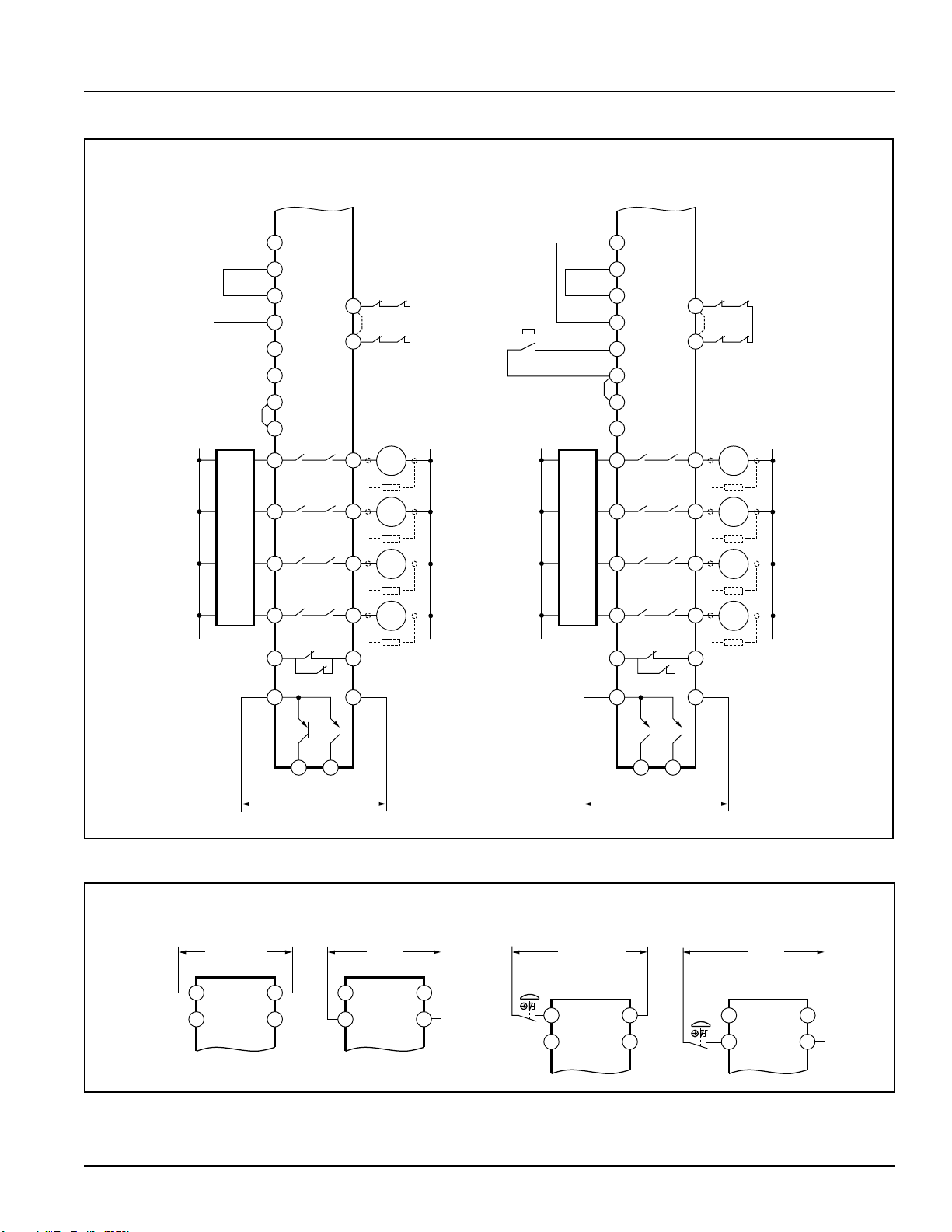
series to the S31-32 feedback input (see Figures 4 and 5). In operation, if one of the
switching contacts of either master stop control element fails in the shorted condition, the
associated monitor contact will remain open. Therefore, it will not be possible to reset
the E-Stop Safety Module. If no MSC-monitor contacts are monitored, a jumper must be
installed between terminals S31 and S32 (see Figures 4 and 5). It is the responsibility
of the user to ensure that any single failure will not result in a hazardous condition
and will prevent a successive machine cycle.
Connection to the Machine to be Controlled
The hookup diagrams (Figures 4 and 5) show a generic connection of the E-Stop Safety
Module’s four redundant output circuits to Master Stop Control Elements MSC1 through
MSC4. A Master Stop Control Element is defined as an electrically powered device,
external to the E-Stop Safety Module, which stops the machinery being controlled by
immediately removing electrical power to the machine and (when necessary) by applying
braking to dangerous motion. This stopping action is accomplished by removing power to
the actuator of either Master Stop Control Element.
Connection of Reset Switch
The Reset Circuit switch can be any mechanical switch such as a normally open
momentary switch, or a two-position key switch. The Reset switch must be capable of
reliably switching 12 to 18V dc at 40 to 100 milliamps. As shown in Figures 4 and 5, the
Reset switch connects between terminals S33 and S34 of the Safety Module.
The Reset switch must be located outside of – and not be accessible from – the
area of dangerous motion, and must be positioned so that any area of dangerous
motion may be observed by the switch operator during the Reset procedure.
To perform a manual reset, close the normally open switch for at least 1/4 second, but no
longer than 2 seconds, and then re-open the switch.
Automatic Reset Mode
Model ES-UA-5A or ES-VA-5A may be used also with automatic reset. If no MSC-monitor
contacts are monitored, a jumper must be installed between terminals S31 and S32 (see
Figures 4 and 5). The E-Stop Safety Module will reset (and the outputs energize) as soon
as the E-stop switch returns to its closed-contact position.
The automatic reset mode is useful for some automated processes. However, if
automatic reset is used, it is necessary to provide an alternate means of preventing
resumption of hazardous machine motion, until an alternate reset procedure is
performed. The alternate procedure must include a Reset/Restart switch, located outside
the area of dangerous motion, which is positioned so that any area of dangerous motion
may be observed by the switch operator during the reset procedure.
Auxiliary Monitor Contact/Solid-State Monitor Outputs Connection
The action of the auxiliary monitor contact, terminals 51/52, inversely “follows” the action
of the safety outputs. The 51/52 auxiliary monitor contact is to be used only for control
functions that are NOT safety-related.
There are two solid-state monitor outputs, each capable of switching up to 100 mA at
12-24V dc. One output at terminal Y32 follows the action of the output circuits (K1 and
K2); the other output at terminal Y35 opens (low signal) when there is an internal power
supply fault. A typical use is to communicate the status of the Safety Module output to a
programmable logic controller (PLC). See Figure 4 for hookup information.
WARNING . . .
Reset
Routine Required
U.S. and international
standards require that a reset routine
be performed after returning the E-stop
switch to its closed-contact position
(when arming the E-stop switch). When
automatic reset is used, an alternate
means must be established to require a
reset routine, after the E-stop switch is
armed. Allowing the machine to restart
as soon as the E-stop switch is armed
creates an unsafe condition which
could result in serious injury or death.
WARNING . . .
Reset Switch Location
Any Reset switch(es) used
must be accessible only from outside,
and in full view of, the hazardous area.
Reset switches must also be out of
reach from within the safeguarded
space, and must be protected against
unauthorized or inadvertent operation
(e.g., through the use of rings or guards).
If any areas are not visible from the
Reset switch(es), additional means of
safeguarding must be provided.

E-Stop Safety Module – Models ES-UA-5A and ES-VA-5A
Initial Checkout Procedure
Checkout procedure:
1.Remove power from the machine control elements.
2.Activate the E-stop switch (open its contacts).
3.Apply power to the E-Stop Safety Module at terminals A1 and A2 or B1 and B2 (see
Figure 6). Verify that only the Input Power indicator (Figure 1) is ON.
If either of the other two indicators is ON at this point, disconnect the input power and
check all wiring. Return to step 2 after the cause of the problem has been corrected.
4.Arm the E-stop switch (close its contacts).
5.Automatic reset: K1 and K2 indicators should come ON, and the safety output
contacts should close.
Manual reset: Close the Reset switch. The K1 and K2 indicators should continue
flashing. Open the Reset switch. The K1 and K2 indicators should both come ON solid
at this time. If either indicator comes ON solid before the Reset switch is opened,
disconnect the input power and check all wiring. Return to step 2 after correcting the
problem.
6.Activate the E-stop switch (open its contacts). The K1 and K2 indicators should turn
OFF simultaneously. If either indicator remains ON, disconnect the input power and
check all wiring. Return to step 2 after the cause of the problem has been corrected.
7.Close the enclosure. Apply power to the Machine Control Elements and perform the
Periodic Checkout Procedure.
NOTE: If more than one E-stop switch is series-connected to one E-Stop Safety
Module, the above checkout procedure must be run individually for
EACH switch.
CAUTION . . .
Disconnect Power
Prior to Checkout
Before performing the initial checkout
procedure, make certain all power
is disconnected from the machine
to be controlled. Dangerous voltages
may be present along the E-Stop Safety
Module wiring barriers whenever power
to the machine control elements is ON.
Exercise extreme caution whenever
machine control power is or may be
present. Always disconnect power to
the machine control elements before
opening the enclosure housing of the
E-Stop Safety Module.
WARNING . . .
Multiple E-Stop
Switches
When two or more E-stop switches are
used, each switch must be individually
actuated (engaged), then rearmed and
the E-stop Safety Module reset (if using
manual reset mode). This allows the
monitoring circuits to check each switch
and its wiring to detect faults. Failure to
test each switch individually in this
manner could result in undetected
faults and create an unsafe condition
which could result in serious injury or
death.

E-Stop Safety Module – Models ES-UA-5A and ES-VA-5A
Figure 7. Model ES-UA-5A/ES-VA-5A E-Stop Safety Module enclosure dimensions
84 mm
(3.3")
45 mm
(1.77")
118.0 mm
(4.65")
45 mm
(1.77")
Periodic Checkout Procedure
The functioning of the E-stop system must be verified on a regular periodic basis to
ensure proper operation (see also the machine manufacturer’s recommendations).
Procedure:
1. With the machine running, engage the E-stop switch (open its contact). Verify that the
machine stops.
2. Return the E-stop switch to its closed-contact position. Verify that the machine does
not restart.
3. Close and then open the Reset switch (if using manual reset mode). Verify that the
machine can be restarted by normal initiation.
NOTE: If two or more E-stop switches are series-connected to one E-Stop Safety
Module, this test must be run individually for EACH switch.
Repairs
NOTE: Do not attempt any repairs to the Emergency Stop Safety Module. It
contains no field-replaceable components. Return the Safety Module to the
factory for warranty repair or replacement.
If it ever becomes necessary to return an E-Stop Safety Module to the factory, please do
the following:
1. Contact the Banner Factory Application Engineering Group at the address or at the
numbers listed at the bottom of the back page. They will attempt to troubleshoot the
system from your description of the problem. If they conclude that a component is
defective, they will issue an RMA(Return Merchandise Authorization)number for your
paperwork, and give you the proper shipping address.
2. Pack the E-Stop Safety Module carefully. Damage which occurs in return shipping is
not covered by warranty.
CAUTION . . .
Abuse of
Module After Failure
If an internal fault has occurred and
the ES-...A-5A will not reset, do not
tap, strike, or otherwise attempt to
correct the fault by a physical impact
to the housing. An internal relay may
have failed in such a manner that its
replacement is required.
If the Module is not immediately
replaced or repaired, multiple
simultaneous failures may accumulate
such that the safety function can not
be guaranteed.
WARNING . . .
Multiple
E-Stop Switches
When two or more E-stop
switches are used, each switch must be
individually actuated (engaged), then re-
armed and the E-Stop Safety Module reset
(if usingmanual resetmode). This allows
the monitoring circuits tocheckeachswitch
and itswiringtodetectfaults. Failure to test
each switch individually in this manner
could result in undetected faults and
create an unsafe condition which could
result in serious injury or death.
To remove a terminal
block, insert a small
screwdriver into the slot
as shown, and pry to
loosen.
Figure 8. Removal of terminal blocks
NOTE: When reinserting the block, take
care to slide the dovetail on the
terminal block into the slot on the
frame.

E-Stop Safety Module – Models ES-UA-5A and ES-VA-5A
Supply Voltage and Current A1-A2: 115V ac (Model ES-UA-5A) or 230V ac (model ES-VA-5A), ± 15%; 50/60Hz
B1-B2: 12-24V dc, ± 15%, 10% max. ripple
Power consumption: approx. 4W/7VA
Supply Protection Circuitry Protected against transient voltages and reverse polarity
Output Configuration Outputs (K1 & K2): four redundant (total of eight) safety relay (forced-guided) contacts – AgNi, 5 µm gold-plated,
plus 1 N/C Auxiliary Monitor output – AgNi, 5 µm gold-plated
Low Current Rating:
Caution: The 5 µm gold-plated contacts allow the switching of low current/low voltage. In these low-
power applications, multiple contacts can also be switched in series (e.g., “dry switching”).
To preserve the gold plating on the contacts, the following max. values should not be exceeded at any time:
Min. voltage: 1V ac/dc Max. voltage: 60V
Min. current: 5 mA ac/dc Max. current: 300 mA
Min. power: 5 mW (5 mVA) Max. power: 7 W (7 VA)
High Current Rating:
If higher loads must be switched through one or more of the contacts, the minimum and maximum values of the
contact(s) changes to:
Min. voltage: 15V ac/dc Max. voltage: 250V ac/dc
Min. current: 250 mA ac/dc Max. current: 6 A
Min. power: 5 W (5 VA) Max. power: 200 W (1500 VA)
Mechanical life: 50,000,000 operations
Electrical life: 150,000 operations (typical, @ 1,500 VA switched power, resistive load)
150,000 operations (typical, @ 200 W switched power, resistive load)
NOTE: Transient suppression is recommended when switching inductive loads. Install suppressors
across load. Never install suppressors across output contacts (see Warning, page 6).
Solid-State Monitor Outputs:
Two non-safety solid-state dc outputs
Output at Y32 monitors state of outputs – conducts (output high) when both K1 and K2 are energized
Output at Y35 conducts (output high) when internal power supply is OK
Output circuits require application of +12-24V dc ± 15% at terminal Y31; dc common at Y30
Maximum switching current: 100 mA at 12-24V dc
Both outputs are protected against short circuits
Output Response Time 25 milliseconds typical
Input Requirements E-stop switch must have normally closed contacts each capable of switching 20 to 50mA @ 12 to 30V dc;
and must be open ≥ 10 ms for a valid stop command. Maximum input resistance 250 Ω per channel.
Reset switch must have one normally open contact capable of switching 20 to 50mA @ 12 to 30V dc.
On-Time Delay 100 ms; time from the E-stop contacts to close (Auto Reset) or the reset button to open (Manual Reset) and the
safety outputs to close.
Status Indicators 3 green LED indicators: Power ON, K1 energized, K2 energized
1 red LED indicator responds to fault of internal power supply, ground fault, or cross-short of input channels (see
“Troubleshooting” on back cover for LED condition descriptions).
Housing Polycarbonate. Rated NEMA 1 (IEC IP20)
Mounting Mounts to standard 35 mm DIN rail track. Safety Module must be installed inside an enclosure rated NEMA 3
(IEC IP54), or better.
Vibration Resistance 10 to 55Hz @ 0.35 mm displacement per IEC 68-2-6
Operating Conditions Operating Temperature: 0° to +50° C (+32° to 122° F)
Maximum Relative Humidity: 90% @ +50° C (non-condensing)
Heat Dissipation Considerations: See page 5
Dimensions See Figure 7, page 10
Certifications
Specifications
EMERGENCY STOP DEVICE
29YL

E-Stop Safety Module – Models ES-UA-5A and ES-VA-5A
P/N 122365 rev. B
WARRANTY:
Banner Engineering Corp. warrants its products to be free from defects for one year. Banner Engineering Corp. will repair or replace,
free of charge, any product of its manufacture found to be defective at the time it is returned to the factory during the warranty period. This warranty
does not cover damage or liability for the improper application of Banner products. This warranty is in lieu of any other warranty either expressed or
implied.
Troubleshooting
Condition Indicator Status Possible Reasons/Solutions
Will not reset Power LED ON
Fault LED OFF
Ch. 1 LED Flashing
Ch. 2 LED Flashing
MSC Monitoring circuit open:
• Check wiring at S31/S32. This must be a closed circuit before module can be reset.
Reset mode-select open:
• Check jumper at S32/S35 (auto reset) or S32/S33 (manual reset).
• Check reset key connection.
Power LED ON
Fault LED OFF
Ch. 1 LED OFF
Ch. 2 LED OFF
Connector(s) loose:
• Ensure connector and wire termination is properly seated.
E-stop button open:
• Re-arm E-stop button.
• Check for short between channels.
Power LED ON
Fault LED OFF
Ch. 1 LED OFF
Ch. 2 LED ON
S11/S12 open; S21/S22 closed:
• Check wiring.
• Check switch.
• Ensure connector and wire termination is properly seated.
• Ensure both input channels are open a minimum of 0.5 seconds.
Power LED ON
Fault LED OFF
Ch. 1 LED ON
Ch. 2 LED OFF
S11/S12 closed; S21/S22 open:
• Check wiring.
• Check switch.
• Ensure connector and wire termination is properly seated.
• Ensure both input channels are open a minimum of 0.5 seconds.
Power LED ON
Fault LED ON or Flashing
Ch. 1 LED OFF
Ch. 2 LED OFF
Internal fault:
• Return to factory for repair or replacement.
All LEDs OFF Possible fault in machine control or wiring to the module:
• Check input power/ground.
• Ensure connector and wire termination is properly seated.
All LEDs Dim Possible fault in machine control or input power:
• Check input power and supply requirements of module.
Intermittently
drops out, able to
reset after cycling
E-stop button
Power LED ON
Fault LED OFF
Ch. 1 LED OFF
Ch. 2 LED OFF
Momentary short between channels (e.g., S11 and S21):
• Check for intermittent short between channels.
MSCs do not
energize Power LED ON
Fault LED OFF
Ch. 1 LED ON
Ch. 2 LED ON
Possible fault in machine control, or an open circuit between machine control and
MSCs:
• Check continuity of safety outputs (e.g., between terminals 13 and 14).
• Check control wires.
• Check MSCs.
Other manuals for ES-UA-5A
1
This manual suits for next models
1
Table of contents
Other Banner Control Unit manuals

Banner
Banner GM-FA-10J User manual

Banner
Banner E-Stop ES-TN-14H5 User manual

Banner
Banner ES-GA-5A User manual

Banner
Banner DX80DR9M-HB1 User manual

Banner
Banner MM-TA-12B User manual

Banner
Banner DUO-TOUCH SG User manual

Banner
Banner ES-TN-1H Series User manual

Banner
Banner DX99N9X1S2N0M2X0D2 User manual

Banner
Banner ES-TA-3F1 User manual

Banner
Banner MMD-TA-11B User manual