TECO-Westinghouse EQ5 Series User manual

EQ5 Drive Quick Start Guide for Constant Torque Applications
TECO Westinghouse Motor Company EQ5 Quick Start Guide 2
Contents
Page
Introduction.................................................................................................................................3
1. EQ5 Model Identification and Mounting ...............................................................................4
2. Input Power and Motor Connection......................................................................................7
3. Check Motor Rotation and Direction.....................................................................................8
4. Speed Reference Configuration............................................................................................9
5. Run / Stop Configuration .....................................................................................................14
6. Digital Operator Panel..........................................................................................................18
7. Motor and Application Specific Settings............................................................................21
Downloaded from Dealers Industrial Equipment -- Visit https://DealersElectric.com or call (908) 688-1966 for all of your Teco needs!

EQ5 Drive Quick Start Guide for Constant Torque Applications
TECO Westinghouse Motor Company EQ5 Quick Start Guide 3
Introduction
This Quick Start Guide is a supplement to other documentation supplied with this equipment
and will help the user in properly wiring the EQ5 and motor. This Quick Start guide is for use
with installing and setting up the EQ5 drive for Industrial Applications (Constant torque, such as
Conveyor belts, Extruders, Punch Press, etc…)
Warning / Danger: Improper wiring can and will cause bodily harm as well as
damage to the equipment
When installing the system be sure to follow good wiring practices and all applicable codes.
Ensure that the mounting of the various components are secure and that the environment, such
as extreme dampness, poor ventilation etc. will not cause system degradation.
Please read this quick start guide in combination with the EQ5 Operations Manual
(Document No. TWMC-EQ5OM provided with the EQ5 thoroughly before attempting any
installation.
Downloaded from Dealers Industrial Equipment -- Visit https://DealersElectric.com or call (908) 688-1966 for all of your Teco needs!

EQ5 Drive Quick Start Guide for Constant Torque Applications
TECO Westinghouse Motor Company EQ5 Quick Start Guide 4
1. EQ5 Model Identification and Mounting
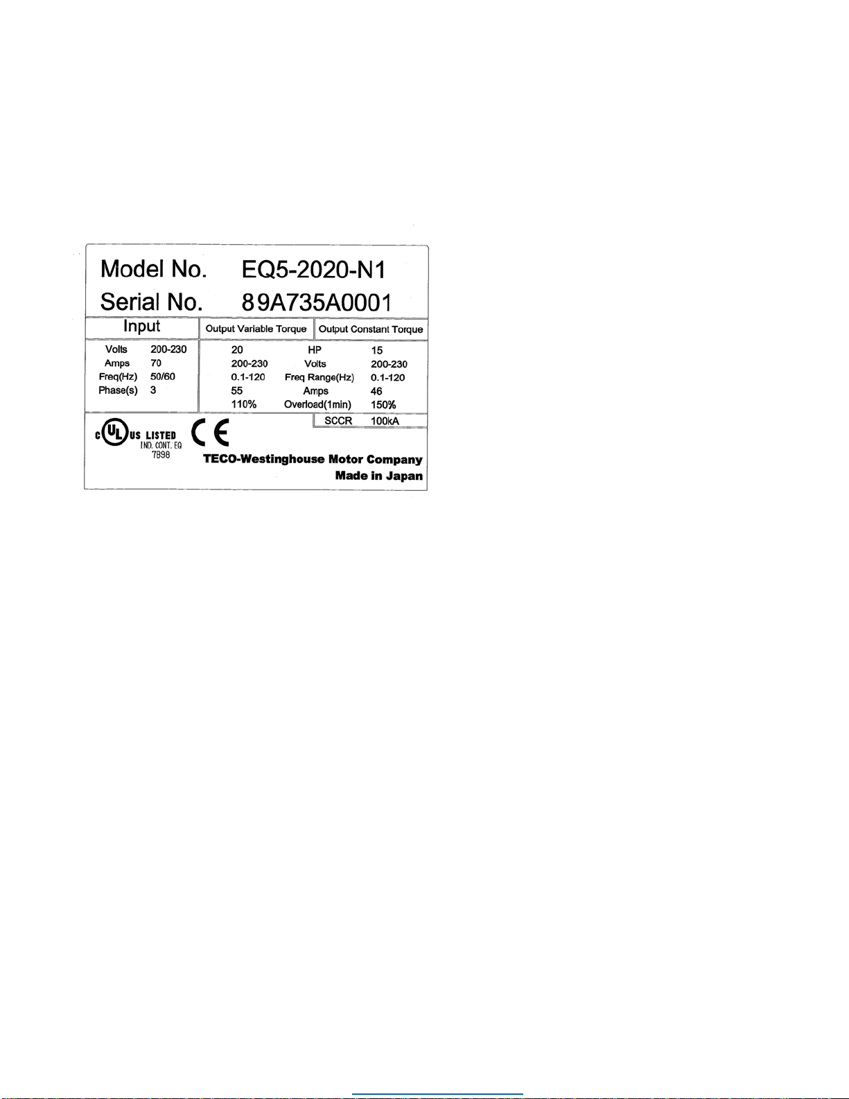
It is essential to verify the EQ5 drive nameplate and make sure that the EQ5 drive has the
correct rating so it can be used with your motor. Please check the EQ5 nameplate information
as shown in the example below.
•Check that the input voltage range meets the input power requirements.
•Ensure that the Constant Torque FLA and Output Voltage rating on the EQ5 drive label
meets the motor requirements (nameplate).
1.2 Mounting
Mounting of the EQ5 drive is extremely important for accessibility as well as for the environment.
Various EQ5 drive models are available and the mounting dimensions (footprint) may be
different. Because the mounting procedure is fairly extensive, it is beyond the scope of this
document, the user is referred to the EQ5 Operations Manual (Document No. TWMC-EQ5OM)
received with the EQ5, Chapter 2 Installation and Electrical Connections. Match the model
that you received and follow the procedure described in the manual to ensure a safe and
functional installation. In cases where the system has more than one EQ5 drive, refer to the
proper clearances required for adequate ventilation. Please pay particular attention to:
•The clearances to be maintained around the enclosure for adequate ventilation.
•The environmental specifications such as avoiding excessive dampness, extreme
temperatures, chemical exposure, corrosive areas etc. to avoid damage to the equipment
and to maintain safety.
Downloaded from Dealers Industrial Equipment -- Visit https://DealersElectric.com or call (908) 688-1966 for all of your Teco needs!

EQ5 Drive Quick Start Guide for Constant Torque Applications
TECO Westinghouse Motor Company EQ5 Quick Start Guide 5
Fig. 2 Removing the Surface Cover (for inverters rated 30HP/CT, 40HP/VT or less)
For drives rated at 40HP/CT, 50HP/VT or more, first remove the six mounting screws, then
remove the cover (see Fig. 3).
Fig. 3 Removing the Surface Cover (for inverters rated 40HP/CT, 50HP/VT or more)
Removing the digital operator
After removing the cover, loosen the mounting screws of the digital operator and remove as
shown in Fig.4.
Fig. 4 Removing the Digital Operator (30HP/CT, 40HP/VT or less)
Downloaded from Dealers Industrial Equipment -- Visit https://DealersElectric.com or call (908) 688-1966 for all of your Teco needs!

TECO Westinghouse Motor Company EQ5 Quick Start Guide 6
For drives rated at 40HP/CT, 50HP/VT or above, loosen the mounting screws
of the digital operator and remove using the finger holds on the digital operator
case (see Fig. 5).
Fig. 5 Removing the Digital Operator (40HP/CT, 50HP/VT and above)
Downloaded from Dealers Industrial Equipment -- Visit https://DealersElectric.com or call (908) 688-1966 for all of your Teco needs!

TECO Westinghouse Motor Company EQ5 Quick Start Guide 7
2. Input Power and Motor Connection
Fig.6 below shows the electrical connections for the input power and motor terminals
for various EQ5 models. Verify the input power and motor terminals of the model you
are installing.WITH POWER OFF, make the appropriate connections.
Make sure to follow good wiring practices and all applicable codes. Ensure
that the equipment is grounded properly as shown.
DANGER, LETHAL VOLTAGES ARE PRESENT- Before applying power to the
EQ5 Drive, ensure that the terminal cover is fastened and all wiring
connections are secure. After the power has been turned OFF, wait at least
five minutes until the charge indicator extinguishes completely before
touching any wiring, circuit boards or components.
GG MOTOR
U/T1 V/T2 W/T3
3Ø Induction
motor
Use L1, L2, L3 for
3Ø Input Power
Connect
frame to
ground
Input
Protection
(Fuse or Circuit
Breaker)
To change direction of
motor rotation swap any
two of the three motor
leads (See Step 2)
L1 L2 L3
(R/L1) (S/L2) (T/L3)
(U/T1)
(V/T2)
(W/T3)
Connect to
chassis
ground
Use L1, L2 for
1Ø Input Power
Connect to
chassis ground
*
INPUT POWER
R/L1 S/L2 T/L3
P1 P(+) N(-)
DB
WARNING DO NOT CONNECT ANY OF THE
FOLLOWING TERMINALS TO EARTH GROUND
Fig. 6
* Make sure the drive is properly sized for single phase input. (consult factory)
Downloaded from Dealers Industrial Equipment -- Visit https://DealersElectric.com or call (908) 688-1966 for all of your Teco needs!

TECO Westinghouse Motor Company EQ5 Quick Start Guide 8
3. Check Motor Rotation and Direction
This test is to be performed solely from the EQ5 keypad. Apply power to the EQ5
drive after all the electrical connections have been made and protective covers have
been re-attached. At this point, DO NOT RUN THE MOTOR, the keypad should
display as shown below in Fig. 3 and the speed reference 0.00 should be blinking.
Next use the and keys to set a speed reference of 5.00 Hz, then
press the button.
The motor should now be operating at low speed running in forward (clockwise)
direction.
Next press on the keypad to stop the motor.
If the motor direction is incorrect, power down the EQ5 drive.
After the power has been turned OFF, wait at least five minutes until the
charge indicator extinguishes completely before touching any wiring, circuit
boards or components.
Using Safety precaution, and referring to Fig.6, swap any two of the three output
leads to the motor (U/T1, V/T2 and W/T3). After the wiring change, repeat Step 3
and recheck motor direction.
PRG
RESET FUNC
DATA
SHIFT
STOP
REV
FWD
RUN
JOG / NORMAL
REMOTE / LOCAL
FWD REV STOP REM LOC COMM JOG
Hz AV%r/minm/minkW
X10 X100
STOP FWD
PRG PRG MENU
F / D LED SHIFT
FWD
STOP
Downloaded from Dealers Industrial Equipment -- Visit https://DealersElectric.com or call (908) 688-1966 for all of your Teco needs!

TECO Westinghouse Motor Company EQ5 Quick Start Guide 9
4. Speed Reference Configuration
The EQ5 offers users several choices to set the speed reference from different
sources. The most commonly used methods are described in the next sections.
Frequency reference command is selected with parameter F01.
This function selects the method by which to set the output frequency.
Setting Range: 0 to 11
4.1 Reference from Keypad (Default Setting, F01 = 0)
Speed reference from digital operator (Keypad) is the default setting. Use the
and keys to change the speed reference.
F 0 1 F R E Q C M D 1
PRG
RESET FUNC
DATA
SHIFT
STOP
REV
FWD
RUN
JOG / NORMAL
REMOTE / LOCAL
FWD REV STOP REM LOC COMM JOG
Hz AV%r/minm/minkW
X10 X100
STOP FWD
PRG PRG MENU
F / D LED SHIFT
F01 Frequency Command 1
Downloaded from Dealers Industrial Equipment -- Visit https://DealersElectric.com or call (908) 688-1966 for all of your Teco needs!

TECO Westinghouse Motor Company EQ5 Quick Start Guide 10
4.2 Reference from External Analog Signal (0-10V / 4-20mA) (F01 = 1)
Analog Reference: 0 – 10 V
G
Connect shield to
ground terminal
0 – 10 V
+
-
Analog Input T12Common T11
G
Connect shield to
ground terminal
4 – 20 mA
+-
Analog Input C1 Common T11
Downloaded from Dealers Industrial Equipment -- Visit https://DealersElectric.com or call (908) 688-1966 for all of your Teco needs!

TECO Westinghouse Motor Company EQ5 Quick Start Guide 11
Potentiometer (Speed Pot):
G
Connect shield to
ground terminal
Potentiometer
1 ~ 5K Ohm
+10V
COM
Analog Input T12
4.3 Reference from Serial Communication RS485 (H30 = 2 or 3)
To set the speed reference for the EQ5 via serial communication parameter H30 has
be set to either a “1” for frequency command via serial communication only or to “3”
for Run/Stop (Operation Command) and Frequency Reference (Frequency
Command).
Default Communication Setting is: Address “1”, 9600 Bits/sec, 1 Start Bit, 1 Stop
Bit, and No Parity
Downloaded from Dealers Industrial Equipment -- Visit https://DealersElectric.com or call (908) 688-1966 for all of your Teco needs!

TECO Westinghouse Motor Company EQ5 Quick Start Guide 12
The serial comm. link function uses RS485 Modbus RTU protocol and allows for:
1) Monitoring (data monitoring, function data check).
2) Frequency setting.
3) Operation command (FWD, REV, and other commands for digital input)
4) Write function data.
Setting range: 0 to 3
Set value Frequency command Operation command
0 Disabled Disabled
1 Enabled Disabled
2 Disabled Enabled
3 Enabled Enabled
Frequency Reference Command Register
EQ5 Frequency Reference Register: 1797 (Decimal)
Bit 0 – Bit 15: 0.00 ~ 120.00 Hz
Examples:
Frequency Reference Command: 10.00 Hz (EQ5 Address: 01)
Command String (hexadecimal): 01 06 07 05 03 E8 98 01
To set the frequency reference to 10.00, a value of ‘1000’ (03E8h) has to be send to
the EQ5
Frequency Reference Command: 30.00 Hz (EQ5 Address: 01)
Command String (hexadecimal): 01 06 07 05 0B B8 9F FD
To set the frequency reference to 30.00, a value of ‘3000’ (0BB8h) has to be send to
the EQ5
Frequency Reference Command: 60.00 Hz (EQ5 Address: 01)
Command String (hexadecimal): 01 06 07 05 17 70 96 AB
H 3 0 L I N K F U N C
H30 Serial link (Function Select)
Downloaded from Dealers Industrial Equipment -- Visit https://DealersElectric.com or call (908) 688-1966 for all of your Teco needs!

TECO Westinghouse Motor Company EQ5 Quick Start Guide 13
To set the frequency reference to 60.00, a value of ‘6000’ (1770h) has to be send to
the EQ5
Note: The last 2 bytes of the command strings consist of a CRC16 checksum,
please refer to the EQ5 Operations Manual (Document No. TWMC-EQ5OM),
chapter 8 for additional information.
Downloaded from Dealers Industrial Equipment -- Visit https://DealersElectric.com or call (908) 688-1966 for all of your Teco needs!

TECO Westinghouse Motor Company EQ5 Quick Start Guide 14
5. Run / Stop Configuration
The EQ5 offers users several choices to run and stop the drive from different
sources. The most commonly used methods are described in the next sections.
Run/Stop Method is selected with parameter F02.
This function sets the operation command input method.
5.1 Run/Stop from Keypad (Default Setting, F02 = 0)
Run from digital operator (Keypad) is the default setting.
Use the Forward key (FWD) to run the drive in forward direction and the Reverse
key (REV) to run the drive in reverse direction. (Note: to disable reverse direction set
parameter H08 to 1)
Use the Stop key (FWD) to stop the drive. (Note: Stop method can be set with
parameter H07, default is ramp to stop)
F 0 2 O P R M E T H O D
PRG
RESET FUNC
DATA
SHIFT
STOP
REV
FWD
RUN
JOG / NORMAL
REMOTE / LOCAL
FWD REV STOP REM LOC COMM JOG
Hz AV%r/minm/minkW
X10 X100
STOP FWD
PRG PRG MENU
F / D LED SHIFT
F02 Operation Method
Downloaded from Dealers Industrial Equipment -- Visit https://DealersElectric.com or call (908) 688-1966 for all of your Teco needs!

TECO Westinghouse Motor Company EQ5 Quick Start Guide 15
5.2 Run/Stop from External Switch / Contact or Pushbutton (F02 = 1)
Use an external contact or switch to Run and Stop drive.
Permanent Switch / Contact
Momentary Contacts (Push Buttons)
G
Connect shield to
ground terminal
START
PUSH BUTTON
STOP
PUSH BUTTON
Note: Stop method can be set with parameter H07, default is ramp to stop.
Downloaded from Dealers Industrial Equipment -- Visit https://DealersElectric.com or call (908) 688-1966 for all of your Teco needs!

TECO Westinghouse Motor Company EQ5 Quick Start Guide 16
5.3 Run/Stop from Serial Communication RS485 (H30 = 2 or 3)
To Run/Stop (Operation Command) the EQ5 via serial communication parameter
H30 has be set to either a “2” for Run/Stop via serial communication only or to “3”
for Run/Stop (Operation Command) and Frequency Reference (Frequency
Command).
Default Communication Setting is: Address “1”, 9600 Bits/sec, 1 Start Bit, 1 Stop
Bit, and No Parity
The serial comm. link function uses RS485 Modbus RTU protocol and allows for:
1) Monitoring (data monitoring, function data check).
2) Frequency setting.
3) Operation command (FWD, REV, and other commands for digital input)
4) Write function data.
Setting range: 0 to 3
Set value Frequency command Operation command
0 Disabled Disabled
1 Enabled Disabled
2 Disabled Enabled
3 Enabled Enabled
H 3 0 L I N K F U N C
H30 Serial link (Function Select)
Downloaded from Dealers Industrial Equipment -- Visit https://DealersElectric.com or call (908) 688-1966 for all of your Teco needs!

TECO Westinghouse Motor Company EQ5 Quick Start Guide 17
Command Register
EQ5 Command Register: 1798 (Decimal)
Bit 0: Run Forward
Bit 1: Run Reverse
Bit 2 ~ Bit 15: Refer to EQ5 AC Drive Operations Manual (chapter 8)
Examples:
Run Forward Command (EQ5 Address: 01)
Command String (hexadecimal): 01 06 07 06 00 01 A9 7F
Run Reverse Command (EQ5 Address: 01)
Command String (hexadecimal): 01 06 07 06 00 02 E9 7E
Stop Command (EQ5 Address: 01)
Command String (hexadecimal): 01 06 07 06 00 00 68 BF
Note: The last 2 bytes of the command strings consist of a CRC16 checksum,
please refer to the EQ5 Operations Manual (Document No. TWMC-EQ5OM),
chapter 8 for additional information.
Downloaded from Dealers Industrial Equipment -- Visit https://DealersElectric.com or call (908) 688-1966 for all of your Teco needs!

TECO Westinghouse Motor Company EQ5 Quick Start Guide 18
6. Digital Operator Panel
The Digital Operator has various functions for inputting, controlling, and displaying
operations such as frequency setting, run/stop command, confirming and changing
function data, confirming status, and copying. Please review and become familiar
with each function before attempting to operate the drive. The Digital Operator can
be removed or inserted during inverter operation, however, if it is removed during a
keypad operation (e.g., run/stop, frequency setting), the inverter will stop and initiate
an alarm.
6.1 Overview and Navigation
Appearance of Digital Operator
LED Monitor:
4-digit 7-segment display used to display data such
as setting frequency, output frequency and alarm
code.
Auxiliary Information Indication for LED Monitor:
Indicates selected units or multiple of the
monitored data shown on the LED monitor and is
displayed on the top line of the LCD monitor. The
symbol indicates selected units or multiple
number. The symbol ▲indicates there is an upper
screen not currently displayed.
LCD Monitor:
Used to display various items of information as
operation status and function data. An operation
guide message, which can be scrolled, is
displayed at the bottom of the LCD monitor. This
LCD monitor has a backlight feature which turns
on when the control power is applied or any
keypad key is pressed. It stays on approximately 5
minutes after the last key stroke.
Indication on LCD Monitor:
Displays one of the following operation status:
FWD: Forward operation
REV: Reverse operation
STOP: Stop
Control Keys
(valid during digital operator operation):
Used for inverter run and stop
Operation Keys:
Used for switching screens, data change,
frequency setting, etc.
Displays the selected operation mode:
REM: Terminal block
LOC: Keypad panel
COMM: Communication terminal
JOG: Jogging mode
The symbol ▼indicates there is a lower screen not
currently displayed.
Run LED :
Downloaded from Dealers Industrial Equipment -- Visit https://DealersElectric.com or call (908) 688-1966 for all of your Teco needs!

TECO Westinghouse Motor Company EQ5 Quick Start Guide 19
Functions of Operation Keys
Operation
Key Main Function
PRG Used to switch the current screen display to the menu screen or switch
to the initial display screen in the operation/trip mode.
Used to switch the LED monitor or to determine the entered frequency,
function code, or data.
Used to change data, move the cursor up or down, or scroll the display
screen.
Used to move the cursor horizontally when changing data. When this
key is pressed with the up or down key, the cursor moves to the next
parameter function block.
Used to cancel the current input data and switch the display screen. If an
alarm occurs, this key is used to reset the trip status (valid only when the
alarm mode initial screen is displayed).
STOP
Used to switch normal operation mode to jogging operation mode or vice
versa. The selected mode is displayed on the LCD screen.
STOP
+ RESET
Switches the operating mode from digital operator to terminal block
operation (Local / Remote), and vice versa. When these keys are
operated, function F01 data is automatically set to 3 if set at 0, or
automatically set to 0 if set from 1 thru 4. The selected mode is
displayed on the LCD screen.
6.2 Programming Parameters
On the program menu screen, select 1. DATA SET. The parameter select screen
appears. Select the desired parameter and set value as follows.
RUN
FWD
PRG PRG MENU
F / D LED SHIFT
The parameter designations (function codes) consist of alphanumeric characters
with unique alphabetical letters assigned to each parameter group (see table on the
next page).
Downloaded from Dealers Industrial Equipment -- Visit https://DealersElectric.com or call (908) 688-1966 for all of your Teco needs!

TECO Westinghouse Motor Company EQ5 Quick Start Guide 20
Parameter Designations and Corresponding Groups
Parameter Group name Remarks
F00 - F42 Fundamental Functions
E01 - E47 Extension Terminal
Functions
C01 - C33 Control Functions of
Frequency
P01 - P09 Motor Parameters
H03 - H39 High Performance
Functions
A01 - A18 Alternative Motor
Parameters
U01 - U61 User Functions
o01 - o55 Optional Functions Can be selected only with an
option connected.
6.3 Monitoring Signals and Status
Select 3. OPR MNTR on the program menu screen to display the current inverter
operating status.
RUN
FWD
PRG PRG MENU
F / D LED SHIFT
Downloaded from Dealers Industrial Equipment -- Visit https://DealersElectric.com or call (908) 688-1966 for all of your Teco needs!
Table of contents
Popular Industrial Equipment manuals by other brands

BMC
BMC KOPA Series instruction manual

Afag
Afag CS 6/20-ED Assembly and operating instructions

Lamtec
Lamtec BT300 BurnerTronic manual

SCHUNK
SCHUNK PSK 16 Assembly and operating manual

Conductix-Wampfler
Conductix-Wampfler MultiLine 0835 Mounting instruction

Mayr
Mayr EAS-Sm Installation and operating instructions