Tecomec GEOline ECU1224 Instruction Manual


ISOBUS ECU 1224 User and Instruction maual |
P00801545 Rev:02 SW:1.0.0
1
1Sommario
1Sommario......................................................................................................................................1
2INTRODUCTION.............................................................................................................................4
3LEGEND .........................................................................................................................................4
4INTENDED USE ..............................................................................................................................5
5WARNINGS....................................................................................................................................5
6PACKAGE CONTENT ......................................................................................................................7
6.1 Product description...............................................................................................................7
6.2 Kit part number .....................................................................................................................8
6.3 ISOBUS ECU 1224 Sprayer Kit Contenent..............................................................................9
7INSTALLATION SCHEME..............................................................................................................10
7.1 Harness and cables..............................................................................................................10
7.1.1 ISOBUS ECU 1224 Scheme up to 9 Sections ................................................................10
7.1.2 ISOBUS ECU 1224 Scheme up to 9 Sections + Hydraulic .............................................11
7.1.3 ISOBUS ECU 1224 Scheme up to 16 Sections ..............................................................12
8INSTALLATION.............................................................................................................................13
8.1 ECU 1224 Installation ..........................................................................................................13
8.1.1 ECU 1224 Positioning...................................................................................................13
8.1.2 Cables connecting ISOBUS ECU 1224...........................................................................14
8.2 Speed sensor installation ....................................................................................................15
8.2.1 Tips for installation.......................................................................................................16
8.3 Flowmeter installation ........................................................................................................17
8.4 Pressure sensor installation ................................................................................................17
8.5 Tank-level sensor installation..............................................................................................17
8.6 Check hardware installation................................................................................................19
8.7 Chemical compatibility........................................................................................................19
9PROGRAMMING USER INTERFACE .............................................................................................19
9.1 Introduction.........................................................................................................................20
9.2 HOME page..........................................................................................................................20
9.3 SETUP page..........................................................................................................................21
9.3.1 Section Width...............................................................................................................27
9.3.2 Speed source setup......................................................................................................28
9.3.3 Flowmeter setup..........................................................................................................28

ISOBUS ECU 1224 User and Instruction maual |
P00801545 Rev:02 SW:1.0.0
2
9.3.4 Pressure sensor setup..................................................................................................29
9.3.5 Tank level sensor setup................................................................................................29
9.3.6 Sprayer geometry.........................................................................................................30
9.3.7 Date-time from tractor TECU.......................................................................................30
9.4 WORK page..........................................................................................................................32
9.5 HISTORY page......................................................................................................................35
9.6 HYDRAULIC CONTROL page.................................................................................................36
9.7 TANK CALIBRATION page ....................................................................................................37
9.8 External warning lights LEDs ...............................................................................................38
9.8.1 Led L1: main status ......................................................................................................39
9.8.2 Led L2: ISOBUS connection status ...............................................................................39
9.8.3 Led L3: error codes.......................................................................................................39
10 IN FIELD USAGE.......................................................................................................................40
10.1 Display .................................................................................................................................40
10.2 Switch-On/Off the ISOBUS ECU 1224..................................................................................41
10.3 Execution of a Treatment....................................................................................................41
10.4 Operating modes.................................................................................................................42
10.4.1 Manual Mode...............................................................................................................42
10.4.2 Automatic Mode ..........................................................................................................43
10.5 Main Valve Driver................................................................................................................44
10.5.1 Independent Mode ......................................................................................................44
10.5.2 Dependent Mode.........................................................................................................45
10.6 Rate indicator ......................................................................................................................45
10.7 Tank Replenishment............................................................................................................45
10.8 Historical Treatments..........................................................................................................46
11 ALARMS...................................................................................................................................47
11.1 Introduction.........................................................................................................................47
11.2 ALARMS ...............................................................................................................................47
11.2.1 Low level ......................................................................................................................47
12 TROUBLESHOOTING................................................................................................................48
13 ACCESSORIES...........................................................................................................................49
13.1 Main cable Connection........................................................................................................49
13.2 Pressure sensor ...................................................................................................................49

ISOBUS ECU 1224 User and Instruction maual |
P00801545 Rev:02 SW:1.0.0
3
13.3 Speed sensor .......................................................................................................................49
13.4 Level Sensor.........................................................................................................................50
14 SPARE PARTS...........................................................................................................................51
15 DIMENSIONS ...........................................................................................................................52
16 TECHNICAL DATA ....................................................................................................................53
17 DECLARATION OF CONFORMITY.............................................................................................56
18 ISOBUS CERTIFICATION...........................................................................................................57
19 WARRANTY..............................................................................................................................58
19.1 Warranty periods...........................................................................................................58
19.2 Product warranty terms................................................................................................58
19.3 Returning goods............................................................................................................59
20 QUICK REFERENCE...................................................................................................................60
20.1 Switch-On/Off the ISOBUS ECU 1224..................................................................................60
20.2 Start new treatment............................................................................................................60
20.3 Operating modes: Automatic, Manual................................................................................60
20.4 Tank Replenishment............................................................................................................60
20.5 Ratio.....................................................................................................................................61
20.6 Change Rate –Manual Mode..............................................................................................61
20.7 Change Rate –Automatic Mode .........................................................................................61
20.8 Terminate treatment...........................................................................................................61

ISOBUS ECU 1224 User and Instruction maual |
P00801545 Rev:02 SW:1.0.0
4
2INTRODUCTION
Congratulations Dear User,
You have chosen a product by Tecomec, a leading company in the development and production
of electronic systems for agriculture. This manual provides information about operating and
maintaining. For your safety and the safety of the people working with this equipment, it is very
important that you read the manual carefully before using this system.
Proper maintenance extends the life of the product and ensures the safe operation of the system.
The manufacturer reserves the right to redesign and change the system as necessary without
notification.
ECU 1224 is an Electronic Control Unit ISOBUS certified, dedicated to sprayer implement. ECU
1224 is a rate controller capable of Automatic Section Control when connected to ISOBUS Virtual
Terminal enabled for GPS navigation. This device works only with certified ISOBUS VT, please
verify documentation of your VT installed on the tractor.
3LEGEND
This user’s manual uses some conventional signs, to lead the user during the reading of important
instructions and advices; these concern especially the setting of the parameters of the system and
thus its correct working.
Please pay attention to the following icons:
Info: Indicates further explaining and
information.
DANGER: Indicates an imminently hazardous
situation that, if not avoided, could result in
DEATH OR VERY SERIOUS INJURY.
WARNING Indicates a potentially hazardous
situation that, if not avoided, may result in
MINOR INJURY or system damage

ISOBUS ECU 1224 User and Instruction maual |
P00801545 Rev:02 SW:1.0.0
5
Indicates an operation that can be repeated
many times, cyclically.
4INTENDED USE
ISOBUS ECU 1224 is high performance electronic control unit for liquid distribution, specially
designed to work on agricultural machinery for spraying. The accurate control of the sprayer
parameters increases the effectiveness and efficiency of the treatments, reducing the waste of
chemicals.
ISOBUS ECU 1224 is certified ISO 11783. The ISO 11783 standard protocol usually called ISOBUS
protocol is the result of an agreement between the main manufacturers of agricultural machinery
and equipment. ISOBUS allows communication between the ISOBUS display installed in most
recent tractors and sprayers, seeder etc. A unique display in the cabin (called Virtual Terminal) will
control your implement, avoiding expensive and bulky proprietary displays. The certification
guarantees you full compatibility with all ISOBUS certified tractor’s consoles.
5WARNINGS
WARNING The power supply must be protected with fuse (10A recommended).
If it is not the case, Tecomec s.r.l is not responsible for damages to ISOBUS ECU
1224.
WARNING: Disconnect power supply cable ECU when battery is undergoing
recharge. If it is not the case Tecomec s.r.l is not responsible for damages to the
ECU.

ISOBUS ECU 1224 User and Instruction maual |
P00801545 Rev:02 SW:1.0.0
6
WARNING: Disconnect power supply ECU before reparations, or welding
procedure on the vehicle. If it is not the case, Tecomec s.r.l is not responsible for
damages to the ECU.
WARNING: For a correct functioning, please make sure that the battery voltage
is higher than 10, 5 Volt.
WARNING: This marking on the product or on its packaging
illustrates that this product may not be disposed of with
normal household waste.
The user is responsible for the disposal of this equipment
through a designated collection of electrical and electronic
equipment. To determine where to dispose of such electrical and electronic
waste, contact the government office, the waste disposal organization serving the family, or the
company where the product was purchased.
WARNING: Before cleaning the implement with high pressure water jets,
protect the equipment from water. Do not orientate high pressure water jet
directly on ECU or cables connected to ECU.
WARNING: Clean equipment using a soft, damp, lint-free cloth. Do not use
sprays, solvents, abrasives, or sharp or pointed objects that could damage
equipment
WARNING: Before operating or installing this equipment read and understand
manual and all safety information. Good safety practices protect operators from

ISOBUS ECU 1224 User and Instruction maual |
P00801545 Rev:02 SW:1.0.0
7
injuries. Safety practices reported in this manual do not override standard good practice.
WARNING: Always check that any suspended vehicle attachments are
lowered to the ground before beginning repair or maintenance work on a vehicle.
WARNING: Wear appropriate protective clothing for the task being undertaken
and conditions.
WARNING: ECU helps the operator to regulate rate control and automatic
section control, but the operator remains the responsible for all the activities.
Operator must keep the control of the vehicle all time. The operator is
ultimately responsible for safe operation of this equipment, preventing and
repairing faulty parts and calibration.
6PACKAGE CONTENT
6.1 Product description
ISOBUS is the term used to denotate standard ISO11783 “tractors and machinery for agriculture
and forestry”. It proposes a standard for the control system and man-machine interface for
systems consisting of tractors and implement such as spraying machines, wagons for
transportation of agricultural products etc. Before the introduction of ISOBUS every equipment
was equipped with its own monitor, which must be positioned in the cab. Thanks to ISOBUS
technology a single graphical console called “Virtual Terminal” is in the cab, and now installed on

ISOBUS ECU 1224 User and Instruction maual |
P00801545 Rev:02 SW:1.0.0
8
the most modern tractors. Virtual Terminal can control any ISOBUS compatible implement. Can
record data about production process and apply varying doses of plant protection products based
on prescription maps using data from the navigation system (GPS) of the tractor.
ISOBUS ECU 1224 regulate chemical quantity, assuring high protection at your crop. Ratio
controller keeps constant and uniform chemical coverage on crop. Compensate speed variation
regulating pressure in sprayer boom using accurate flow measurement.
Automatic Section Control will avoid spraying overlap in case Virtual Terminal is enabled for GPS
section control
Figure 1
6.2 Kit part number
ECU 1224 Kit contains ECU 1224 and all cables necessary for valves and sensors connection.
Kit is composed by Electronic ECU (A), and cables for valve connections: (C2), (C3) see. Main
connection cable (C1) with ISOBUS connector is not included; it must be ordered separately
according the minimum length required. See chapter ACCESSORIES.
Depending on harness included in ISOBUS ECU 1224can operate:
•From 2 up to 11 motorized valves (use 2 Wires valve connection, 12 Volts: 9 section valves,
main valve, and regulation valve)
•from 2 up to 18 motorized valves (use 3 Wires valve connection, 12 Volts: 16 section
valves, main valve, and regulation valve)

ISOBUS ECU 1224 User and Instruction maual |
P00801545 Rev:02 SW:1.0.0
9
Here reported codes for ordering
Table 1
8410075
ISOBUS ECU 1224 SPRAYER from 2 up to 6W 2WIRES VALVE
8410074
ISOBUS ECU 1224 SPRAYER from 2 up to 7W 2 WIRES VALVE
8410073
ISOBUS ECU 1224 SPRAYER from 2 up to 9W 2 WIRES VALVE
8410076
ISOBUS ECU 1224 SPRAYER from 2 up to 11W 3 WIRES VALVE
8410077
ISOBUS ECU 1224 SPRAYER from 2 up to 13W 3 WIRES VALVE
8410078
ISOBUS ECU 1224 SPRAYER from 2 up to 16W 3 WIRES VALVE
6.3 ISOBUS ECU 1224 Sprayer Kit Contenent
•User manual and instruction
•A) ISOBUS ECU 1224
•C2) Valve/sensors connection cable (Gray connector)
•C3) Valve/sensors connection cable (Brown connector) *
•T1) ISOBUS terminator ( connect on ISOBUS cable , ISOBUS Cable must be purchased apart)
*C3 cable can be present or not depending on Kit composition, in case your kit drives more than 6
section valves Brown connector cable is included in kit
Figure 2

ISOBUS ECU 1224 User and Instruction maual |
P00801545 Rev:02 SW:1.0.0
10
7INSTALLATION SCHEME
In this chapter are reported schemes and information about hardware installation
7.1 Harness and cables
ISOBUS ECU 1224 is a full electronic integrated system for dose regulation and Automatic Section
control if connected to an ISOBUS Task Controller enabled for this function.
Kit is composed by Electronic ECU (A), and cables for valve connections: (C2), (C3) See Figure 2 .
Main connection cable (C1) must be ordered separately according to the minimum length
required. See chapter ACCESSORIES.
Use only cables designed and produced by Tecomec for ISOBUS ECU 1224, the use of non-original
parts invalidates the product warranty and does not guarantee the correct operation of the device
7.1.1 ISOBUS ECU 1224 Scheme up to 9 Sections
Here below schematic connection for (Kit part number 8410073) scheme report 9 section valves
sprayer.
Kit part number 8410073 include harness for 2 wires operated valves
Figure 3 Kit part number: 8410073 includes A, C2, C3.

ISOBUS ECU 1224 User and Instruction maual |
P00801545 Rev:02 SW:1.0.0
11
Table 2
PART
Description
PART
Description
A
Driver ISOBUS ECU 1224
I
Pump
--
----------
L
Tank
--
----------
--
----------
D
Speed sensor (Optional)
N
Sprayer Boom
E
Foam marker (Optional)
C1
Main cable
F
Level Sensor (Optional)
C2
Gray connector valve cable
G
Pressure sensor (Optional)
C3
Brown connector valve cable
H
Electric valves
--
----------
7.1.2 ISOBUS ECU 1224 Scheme up to 9 Sections + Hydraulic
This configuration requires additional ECU for Hydraulic distributor Here below schematic
connection for a 9 section valves sprayer with Hydraulic electric distributor. In this example we
suppose we are using 2 wires operated valves
External ECU for hydraulic management must be purchased separately contact your supplier for
part number.
Figure 4
Table 3
PART
Description
PART
Description
A
Driver ISOBUS ECU 1224
I
Pump
B
ECU Hydraulic function
L
Tank
C
Hydraulic electric distributor
M
Hydraulic sprayer system
D
Speed sensor (Optional)
N
Sprayer Boom
E
Foam marker (Optional)
C1
Main cable
F
Level Sensor (Optional)
C2
Gray connector valve cable

ISOBUS ECU 1224 User and Instruction maual |
P00801545 Rev:02 SW:1.0.0
12
G
Pressure sensor (Optional)
C3
Brown connector valve cable
H
Electric valves
C4
ECU Hydraulic cable adapter
7.1.3 ISOBUS ECU 1224 Scheme up to 16 Sections
Here below schematic connection for a 16 section valves sprayer with Hydraulic electric
distributor. In this example we suppose we are using 3 wires operated valves
Example of kit: 8410078 ISOBUS ECU 1224 from 2 up to 16W 3 WIRES VALVE
Figure 5
Table 4
Part
Description
Part
Description
A
Driver ECU 1224
I
Pump
L
Tank
C
Hydraulic electric distributor
D
Speed sensor (Optional)
N
Sprayer Boom
E
Foam marker (Optional)
C1
Main cable
F
Level Sensor (Optional)
C2
Gray connector valve cable
G
Pressure sensor (Optional)
C3
Brown connector valve cable
H
Electric valves 3 wires
ISOBUS ECU 1224 User and Instruction maual |
P00801545 Rev:02 SW:1.0.0
13
8INSTALLATION
8.1 ECU 1224 Installation
ECU 1224 must be installed near electric valves in an area protected by accidental shock and
reduced vibrations.
Protect ECU 1224 by heat produced by implement
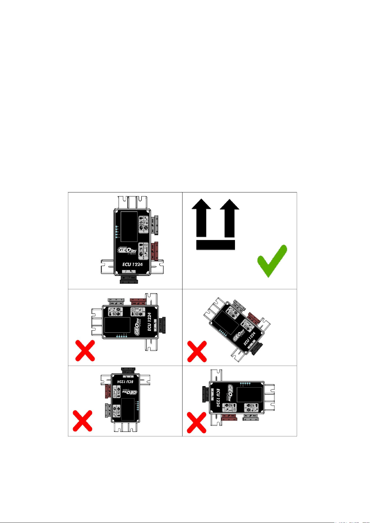
8.1.1 ECU 1224 Positioning
Fix driver box on a flat surface applying 4 screws into the predefined holes. For better sealing
performance set ECU top down as reported in table below.
Figure 6

ISOBUS ECU 1224 User and Instruction maual |
P00801545 Rev:02 SW:1.0.0
14
8.1.2 Cables connecting ISOBUS ECU 1224
Figure 7
Table 5
Connector
Description
Connector
Description
C1
Black connector for ISOBUS main
cable connection
C3
Brown connector for valves,
flowmeter and optional sensors
C2
Grey connector for valves and
optional sensors
The cabling of Input sensors and Output need to be completed before the main cable is plugged to
tractor.
Unused connectors should be protected with a blanking plug or plastic bag to prevent oxidation
Figure 8
Do NOT use high pressure washing machines directly on harness and ISOBUS ECU 1224.

ISOBUS ECU 1224 User and Instruction maual |
P00801545 Rev:02 SW:1.0.0
15
Table 6
Power cable should be fixed to a support at a distance of at least 30cm from the connector itself to
relieve the weight of the cable.
Secure the cables with ties where possible. Repeat this operation for all the connectors of the
driver box.
8.2 Speed sensor installation
The wheel speed sensor is directly connected to ISOBUS ECU 1224 driver and when used as speed
source, it shall be correctly configured in the SETUP page of the user interface (refer to chapter 9)
It shall be mounted in the proximity of the rim’s bolts (refer to Figure 9 ) and by detecting the
transit of every bolt, it will be able to determine the distance covered in a time base.

ISOBUS ECU 1224 User and Instruction maual |
P00801545 Rev:02 SW:1.0.0
16
Figure 9
The speed sensor is provided with a cable terminating with a 3-poles male connector, plug this
connector in the female multi connector cable provided with the ISOBUS ECU 1224 . Sensor input
plug is part of harness Connector C3 (Gray connector 24 pin), Label “S”
Figure 10
The pinout of the female connector provided with the ISOBUS ECU 1224
Table 7
Description
Color
1
GND
BLACK
2
Power
BROWN
3
Signal
BLU
8.2.1 Tips for installation
- Install the sensor at 4-5 mm maximum distance from the nut to be detected.
- Do not install the sensor body too close to other metal objects which could affect the operation
of the detector.

ISOBUS ECU 1224 User and Instruction maual |
P00801545 Rev:02 SW:1.0.0
17
8.3 Flowmeter installation
The flowmeter is directly connected to ISOBUS ECU 1224 and measure flow in the control unit
during a spraying treatment, it shall be correctly configured in the SETUP page of the user
interface (refer to Flowmeter setup Chapter 9.3.2)
The flowmeter shall be provided with a cable terminating with a 3-poles male connector, that will
be plugged with the related female of the connection cable provided with ISOBUS ECU 1224.
Sensor input plug is part of harness Connector C2 (Gray connector 24 pin), Label “F”
The pinout of the female connector provided with the ISOBUS ECU 1224 driver cable is the
following
Table 8
PIN
Description
Color
1
GND
BLACK
2
Power
RED
3
Signal
GREEN
8.4 Pressure sensor installation
The pressure sensor is optional. can be used for pressure measure or flow regulation. For specific
applications, user can decide to use Pressure sensor instead of flow sensor.
Sensor is connected to the ISOBUS ECU 1224 and can measure the liquid pressure during a
spraying treatment, it shall be correctly configured in the SETUP page of the user interface (refer
to chapter 9)
The pressure sensor shall be provided with a cable terminating with a 3-poles male connector, that
will be plugged with the related female of the connection cable provided with the ISOBUS ECU
1224. Sensor input plug is part of harness Connector C2 (Gray connector 24 pin), label “P”
The pinout of the female connector provided with the ISOBUS ECU 1224 driver cable is the
following
Table 9
PIN
Description
Color
1
GND
BLACK
2
Power
RED
3
Signal
GREEN
8.5 Tank-level sensor installation
The tank-level sensor is optional. Level sensor is noyt used for rate regulation. Level sensor is
directly managed by the ISOBUS ECU 1224 driver and if installed to manage the detection of the

ISOBUS ECU 1224 User and Instruction maual |
P00801545 Rev:02 SW:1.0.0
18
product quantity currently contained in the tank, it shall be correctly configured in the SETUP page
of the user interface (refer to sections 9.3 and 9.3.5).
The tank-level sensor shall be provided with a cable terminating with a 3-poles male connector,
that will be plugged with the related female of the connection cable provided with the ISOBUS
ECU 1224. Sensor input plug is part of harness Connector C3 (Brown connector 24 pin), label “L”.
The pinout of the female connector provided with the ISOBUS ECU 1224 driver cable is the
following
Table 10
PIN
Description
Color
1
GND
BLACK
2
Power
RED
3
Signal
GREEN

ISOBUS ECU 1224 User and Instruction maual |
P00801545 Rev:02 SW:1.0.0
19
8.6 Check hardware installation
Before plug ISOBUS ECU 1224 connector to ISOBUS PLUG installed on the tractor check
the correct installation of each component:
•Check that the connectors are in the right locations
•Check that the cables have the right length
•Check that all screws are tight
•Check the polarity and the supply voltage
•Verify there is enough space for folding unfolding sprayer.
8.7 Chemical compatibility
The table below shows the material used for ISOBUS ECU 1224.
Please verify compatibility with chemical products used for spraying.
Table 11
DESCRIPTION
Body
Nylon reinforced with
fiber glass
Connectors
PA6
Screws
Stainless steel
Resin
Bicomponent
poliuretanic
9PROGRAMMING USER INTERFACE
This manual suits for next models
8
Table of contents
Other Tecomec Control Unit manuals


Popular Control Unit manuals by other brands

Trenz Electronic
Trenz Electronic TE0712 TRM manual

Teletek electronics
Teletek electronics ARGUS Installation, programming, and user's manual

urmet domus
urmet domus DIGIVOICE K-Steel 1038/16 Guide

Edgewater Wireless Systems, Inc.
Edgewater Wireless Systems, Inc. EWC24GWFR1 user manual

Beckhoff
Beckhoff PS2001-2420-0000 Documentation

Rittal
Rittal SV9343.070 Assembly instructions


