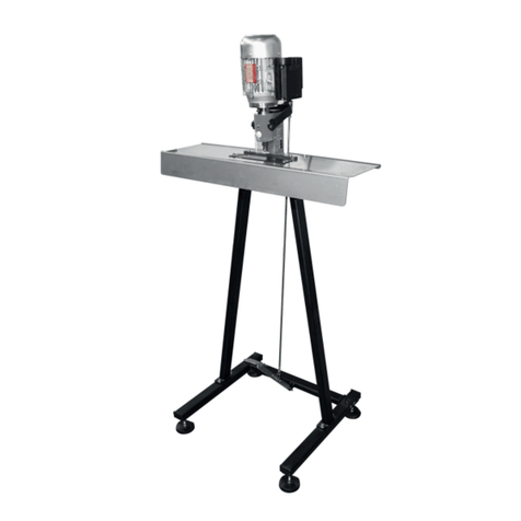
Tecomec RIVET MASTER 120Vac User manual

MANUALE ISTRUZIONI
MANUEL D’INSTRUCTIONS
OWNER’S MANUAL
GEBRAUCHSANWEISUNG
MANUAL DE INSTRUCCIONES
MANUAL DE INSTRUÇÕES
EGCEIRIDIO CRHSHS
GEBRUIKSAANWIJZING
BRUKSANVISNING
BRUKSANVISNING
OHJEKIRJA
BRUGSANVISNING
INSTRUKCJA OBSLUGI
PRÍRUCKA
I
F
GB
D
E
P
GR
NL
S
N
FI
DK
mod. RIVET MASTER
PL
ˇ
ˇ
CZ
®
230Vac
120Vac

RIVET MASTER®
2
5
3
2
4
1
9
8
1
2
3
4
7
5
4
6
FRONT
FRONT

RIVET MASTER®
3
6
9
9/A
6/A
7 8

RIVET MASTER®
4
15
14
10
10/A
11
12 13

RIVET MASTER®
5
16 17
18 19
21
20

RIVET MASTER®
6
22 23
24 25
26
25/A

RIVET MASTER®
7
32
31
27 28
1
29 30

MANUALE ISTRUZIONI RIVETTATRICE ELETTRICA PER CATENE DI MOTOSEGA ED ELETTROSEGA
RIVET MASTER 120Vac
RIVET MASTER 230Vac
Ci complimentiamo con Lei per l'acquisto della rivettatrice elettrica RIVET MASTER. Se usata correttamente sarà uno strumento di lavoro rapido,
comodo e preciso. Perchè il Vostro lavoro sia sempre sicuro e dia buoni risultati rispettate scrupolosamente le istruzioni riportate nel presente
manuale. Per ragioni di sicurezza e un corretto uso della Rivettatrice, si rende necessario leggere attentamente il manuale istruzioni prima della
messa in opera. In dotazione ad ogni macchina viene fornita una copia di questo manuale, conservatelo con cura.
N.B.: Le descrizioni e le illustrazioni contenute nel presente manuale si intendono non rigorosamente impegnative.
La Ditta si riserva il diritto di apportare eventuali modifiche senza impegnarsi ad aggiornare di volta in volta questo manuale.
1 SIMBOLOGIA SULLA MACCHINA
Importante! Le istruzioni contrassegnate con questo simbolo vanno seguite con la massima attenzione.
Usare sempre la macchina con occhiali di protezione.
Usare sempre la macchina con i guanti.
2 CARATTERISTICHE DELLA MACCHINA
- Costruttore: Tecomec SpA - Via Secchi, 2 - 42011 Bagnolo in Piano - Reggio Emilia - ITALY
- Macchina: Rivettatrice elettrica per catene RIVET MASTER.
DATI E MODELLI
- Versioni: RIVET MASTER 230Vac - RIVET MASTER 120Vac
- Potenza installata: Motore elettrico 50Hz 300Wtensione 230Vac - 60Hz 400Wtensione 120Vac
- Velocità massima: (1400 min-1 230Vac) - (1700 min-1 120Vac)
- Livello di pressione acustica: < 70dB (A)
- Tipi di catene rivettabili: passi 1/4" - .325 - 3/8" - .404 / 90SG-91-25AP-HARVESTER
- Peso della macchina completa: 275 N (28 kg)
3 GARANZIA
- La validità della garanzia sul prodotto é quella riconosciuta nel paese di vendita. La richiesta di garanzia ha valore solo se accompagnata
da copia del documento di acquisto (fattura o scontrino di cassa). Per eventuali riparazioni la macchina dovrà essere inviata al rivenditore
in Porto Franco.
- La garanzia decade se:
a) la rivettatrice è stata manomessa;
b) la rivettatrice non è stata usata nel modo indicato dal presente manuale;
c) sulla macchina sono montati pezzi - attrezzi non originali e/o non autorizzati;
d) la rivettatrice è stato collegata a tensioni diverse da quelle indicate sulla targhetta della macchina.
4 SICUREZZA
4.1 AVVERTENZE GENERALI
- La rivettatrice deve essere usata esclusivamente da persone adulte, in buone condizioni fisiche e a conoscenza delle norme d'uso.
- Non indossare bracciali, monili, collari, accessori o indumenti che possono entrare in contatto con le parti rotanti.
- Durante le fasi di lavoro indossare sempre gli occhiali protettivi e i guanti.
- Non usare cavi o prolunghe difettose e/o non a norma.
- Disinserire immediatamente la spina dalla rete se il cavo è danneggiato. Per la riparazione o sostituzione rivolgersi esclusivamente al rivenditore
di fiducia o centro di assistenza autorizzato.
-
Il collegamento elettrico deve essere disposto in modo da evitare che persone o altre macchine possano danneggiarlo, causando situazioni di pericolo.
- Prima di avviare la rivettatrice assicurarsi che la zona di lavoro sia sgombra da utensili o altri oggetti.
- Non permettere ad estranei di sostare nelle vicinanze della rivettatrice o di toccare il cavo di alimentazione durante il suo funzionamento.
- Per le operazioni di manutenzione seguire sempre le istruzioni sotto riportate.
- Non lavorare mai con una rivettatrice danneggiata o modificata arbitrariamente.
- Non togliere o danneggiare o rendere inefficaci i dispositivi di sicurezza.
- Consentire l'utilizzo della rivettatrice soltanto a persone esperte ed a conoscenza del funzionamento e del corretto utilizzo della macchina.
- Collegare la rivettatrice ad una presa di corrente provvista di una di una efficace contatto di terra, in caso di dubbio far effettuare una verifica
da personale tecnico qualificato.
- Scollegare sempre la spina della presa di corrente, prima di effettuare qualsiasi operazione di manutenzione, lubrificazione o pulizia.
- Tenere ben illuminata l’area di lavoro.
- Non usare la rivettatrice alla presenza di liquidi o di gas infiammabili.
- Proteggersi dalle scosse elettriche. Evitare il contatto del corpo con superfici metalliche, estranee alla macchina, messe a terra.
- Non tirare mai il cavo per scollegarlo dalla presa. Tenere lontano il cavo da fonti di calore e spigoli vivi.
- Durante le fasi di lavoro mantenere una buona posizione ed equilibrio appropriato.
- Lavorare sempre in posizione stabile, sicura e prestar e la massima attenzione senza distrarsi.
- Se posizionando l’interruttore su “1” la rivettatrice non si avvia, se l’interruttore è posizionato su “0” la rivettatrice non si arresta, scollegare
immediatamente il cavo di alimentazione dalla rete.
4.2 RISCHI RESIDUI
- Rischio di danno, dovuto ad accensione accidentale. Non usare in area dove possono essere presenti dei bambini.
- Non esporre la macchina a pioggia o ad eccessiva umidita'.
- Quando la rivettatrice non e' utilizzata dislocarla in ambienti e/o luoghi non accessibili ai bambini.
- Quando la macchina viene utilizzata all'aperto con prolunghe, assicurarsi che queste siano a norme e adatte all'uso.
ITALIANO
8

- Non utilizzare la macchina quando l'operatore è stanco.
- Per tutte le operazioni di riparazione e/o sostituzione di parti della macchina difettose o usurate che non sono descritte nelle istruzioni d'uso,
rivolgersi esclusivamente al rivenditore di fiducia.
- La macchina è stata progettata per rivettare esclusivamente le catene per motoseghe ed elettroseghe come indicato nel capitolo Caratteristiche
della Macchina.
5 CONTROINDICAZIONI D'IMPIEGO
- E' vietato utilizzare la rivettarice per cianfrinare o rivettare manufatti che non siano catene.
- Non forzare la rivettatrice durante le fasi di lavoro.
- La macchina puo' essere usata solamente come descritto nel capitolo Installazione.
- La macchina non puo' funzionare a tensioni diverse da quelle indicate.
6 TRASPORTO
- La macchina viene fornita dentro due scatole di cartone riciclabile, una contenente il gruppo motore, l'altra contenente le strutture di sostegno.
Le scatole devono essere maneggiate con cura evitando che subiscano urti durante gli spostamenti.
7 INSTALLAZIONE
La macchina viene fornita in due confezioni separate: confezione gruppo motore e confezione gruppo telaio. All’interno del gruppo motore troverete:
motore elettrico direttamente applicato al suo supporto, una confezione di viti necessarie per fissare il gruppo motore al gruppo telaio e una
confezione con all’interno i porta testina A e B con i relativi contrasti più lo schermo di protezione trasparente.
All’interno del gruppo telaio, troverete i seguenti componenti sciolti:
- n. 1 piano appoggio catena (foto 1 part.1)
- n. 1 montante destro (foto 1 part.2)
- n. 1 montante sinistro (foto 1 part.3)
- n. 2 strutture di sostegno complete di piedini regolabili (foto 1 part.4)
- n. 1 traversa porta pedale (foto 1 part.5)
- n. 1 pedale (foto 1 part.6)
- n. 1 asta completa di due forcelle più una confezione con all’interno viti e rondelle necessarie per assemblare la struttura (foto 1 part.7)
- n. 3 ganasce di fermo catena (foto 1 part.8)
- n. 1 guida appoggio catene (foto 1 part.9)
Per un corretto montaggio della struttura seguire le istruzioni riportate in sequenza:
1 - fissare i due montanti (destro part.2 – sinistro part.3) alle due strutture complete di piedini (part. 4) usando n.2+2 viti M8x16 più n.4 rondelle
grower in dotazione (foto 2). Rispettare il senso di montaggio delle strutture come indicato in (foto 3)
2 - unire i due montanti completi di strutture usando la traversa porta pedale (part.5) mediante n.2+2 viti M6x12 più n.4 rondelle grower in
dotazione (foto 4)
3 - fissare il pedale (part. 6) alla traversa porta pedale mediante perno e copiglia in dotazione (foto 5)
4 - assemblare il gruppo motore alla struttura, unendo i due montanti e fissare il tutto con n.4 viti M8x14 più n.4 rondelle grower in dotazione
(foto 6 e 6/A)
5 - fare scivolare il piano appoggio catena sotto l’albero porta testine (foto 7), posizionarlo correttamente sui due montanti e fissarlo usando
n.2 viti a testa svasata M5x16 più n.2 dadi M5 in dotazione (foto 8)
6 - prendere le tre ganasce di fermo catena (part. 8) in dotazione, sovrapporle una sopra all’altra e con n.2 viti M6x25 fissarle al piano appoggio
catena, facendo attenzione di posizionarle correttamente rivolgendo la parte scaricata dal lato del supporto motore (foto 9 e 9/A)
7 - prendere la guida appoggio catene (part. 9), appoggiarla sul pianale, facendo attenzione di rivolgere la nicchia di forma raggiata verso il
supporto motore. Fare combaciare le asole della guida con i due sottostanti fori del pianale, infilare dall’alto n.2 viti a testa tonda e quadro
sotto testa M5x20 e fissare il tutto con due pomoli in dotazione avvitandoli da sotto (foto 10 e 10/A)
8 - fissare la forcella completa di asta (part. 7) al pedale mediante perno e copiglia in dotazione (foto 11) facendo attenzione di fissare il lato
dove la forcella e asta sono privi di dado
9 - liberare la molla di richiamo dal motore (foto 12) in modo da rendere più agevole il fissaggio della forcella superiore alle due flange
mediante perno e copiglia in dotazione (foto 13)
10 - riagganciare la molla di richiamo al motore usufruendo della vite a viola montata sulla carcassa del motore (foto 14)
8 MONTAGGIO PORTA TESTINA E CONTRASTO
La macchina viene fornita con: porta testina, contrasto e schermo di protezione smontati.
All’interno della confezione del motore, troverete una testina e contrasto tipo Ada utilizzare per catene (vedi fig 1) e una testina e contrasto
tipo Bda utilizzare per catene (vedi fig 2).
Per il montaggio dei tre componenti sopra citati seguire le indicazioni sottostanti:
1 - scegliere la testina e il contrasto in base al tipo di catena da ribadire
2 - avvitare manualmente la testina sull’albero fino a battuta (foto15)
3 - dotarsi di una chiave fissa es.14 e di una chiave es. 23
4 -
abbassare leggermente la testina agendo sul pedale, impugnare con la mano sinistra la chiave es.14 e bloccare l’albero porta testina (foto 16)
5 - impugnare con la mano destra la chiave es.23 serrare il tutto azionando sull’esagono del porta testina (foto 17)
6 -
scegliere il contrasto corrispondente alla testina appena montata e inserirlo all’interno della propria sede (foto 18). Consultare la tabella specifica.
7 - prendere lo schermo di protezione trasparente in dotazione ed asportare le due pellicole di protezione (foto 19)
8 - dotarsi di un cacciavite con estremità a stella e di dimensioni adeguate alle viti di fissaggio
9 - fissare lo schermo di protezione al supporto nei tre punti indicati come da (foto 20) usufruendo di tre viti autofilettanti in dotazione
ATTENZIONE: lo schermo trasparente è uno schermo di protezione sia per gli occhi che per le mani. Non è consentito operare sulla macchina
priva di schermo in quanto viene a meno un importante elemento di sicurezza. In tale caso la Ditta costruttrice si solleva da ogni tipo di responsabilità
in caso di infortunio accidentale dovuto proprio alla mancanza dello schermo.
NOTA: il contrasto si posiziona liberamente nella propria sede e lo si può sostituire senza rimuovere sia lo schermo di protezione che la testina.
Non utilizzare mai la macchina con testina e contrasto di tipo differenti.
9 REGOLAZIONI PRELIMINARI (N.B. tutte le regolazioni della macchina vanno effettuate con il cavo di alimentazione scollegato dalla rete)
1 - regolare i quattro piedini della struttura in modo da rendere la macchina stabile, senza dondolii e sicura durante l’utilizzo (foto 21)
2 - dopo avere verificato che l’impianto elettrico della rete sia conforme alle norme vigenti. in particolare deve essere dotato di protezione
9

differenziale (salvavita) e che il voltaggio della linea corrisponda al voltaggio indicato sulla targhetta dati tecnici della macchina, si può inserire
la spina del cavo di alimentazione nella presa dell’impianto.
Il gruppo asta con forcelle regolabile, è stato pensato per regolare la distanza del pedale dal piano terra e la distanza della testina dal
contrasto. Il gruppo asta viene fornito con le due forcelle regolate in modo che la distanza tra la testina e il contrasto sia massima e la distanza
del pedale dal piano terra sia minimo dai 3 ai 4 cm (1”1/4 – 1”1/2). In questa posizione si può ribadire qualsiasi tipo di catena.
Nel caso si ritenga eccessiva la distanza tra testina e contrasto (es. per ribadire delle catene molto piccole tipo 91VS) esiste la possibilità di
regolare tale distanza eseguendo queste operazioni:
3 - porsi sul lato destro della macchina, con una chiave esagonale di 13 allentare il dado sotto alla forcella superiore (foto 22)
4 - impugnare l’asta con le mani e ruotare la stessa in senso antiorario (foto 23). In questo modo si riduce la distanza tra testina e contrasto
5 - trovata la giusta posizione sempre con una chiave esagonale di 13 serrare il dado contro la forcella
ATTENZIONE ! durante la fase di ribaditura, quando la testina inizia a ruotare tende a trascinare anche la catena. Dopo un piccolo accenno di
rotazione la catena si blocca contro il piano delle tre ganasce fissate sul piano appoggio mettendo l’operatore in condizione di assoluta sicurezza.
L’uso dei guanti e occhiali protettivi è obbligatorio.
10 MESSA IN FUNZIONE
1 - preparare la catena da assemblare appoggiandola sul pianale, prendere la maglia di unione con i rivetti rivolti verso l’alto e infilare le
due estremità della catena sui due rivetti (foto 24)
2 - prendere la maglia di unione forata e centrarla sui due rivetti (foto 25 e 25/A)
3 -
impugnare la catena sia a destra che a sinistra rispetto alla maglia da rivettare ad una distanza consigliata tra le mani di 20cm (8”) circa (foto 26)
4 - tenere in tensione la catena, farla scivolare sotto la protezione trasparente del supporto e appoggiare correttamente uno dei rivetti della
maglia di collegamento sul contrasto concavo (foto 27)
5 - a questo punto anche la parte sporgente delle maglie di trascinamento saranno correttamente appoggiate sulla guida di appoggio catena
(foto 27 punto 1)
ATTENZIONE: controllare che la posizione della guida di appoggio catena, non precluda la corretta posizione del rivetto sul contrasto. Il
bordo della guida non deve mai toccare la maglia di congiunzione sottostante. Si consiglia di lasciare sempre una distanza di: (vedi fig 3).
Per regolare la guida allentare i due pomoli sottostanti, spostare la guida in avanti verso il motore all’indietro verso di sé. Trovato la giusta
posizione bloccare il tutto serrando nuovamente i due pomoli sottostanti.
6 - azionando l’interruttore principale posto sul lato superiore della scatola a lato destro del motore, la macchina si metterà in moto, facendo
ruotare la testina ribaditrice in senso orario (il senso di rotazione della testina è indicato da una etichetta con freccia di colore rosso applicata
sulla parte frontale del motore)
7 - avvicinare gradualmente la testina al rivetto premendo sul pedale senza bruschi movimenti (foto 28) iniziando a ribadire il rivetto
ATTENZIONE: durante la fase di ribaditura, quando la testina inizia a lavorare tende a trascinare la zona interessata della catena. Dopo
un piccolo accenno di rotazione la catena si blocca contro il piano formato dalla tre ganasce fissate sul piano di appoggio mettendo l’operatore
in condizione di assoluta sicurezza. L’uso dei guanti e degli occhiali è comunque obbligatorio.
8 - nel caso in cui il rivetto risulti troppo (o poco) schiacciato, si deve intervenire sulla apposita ghiera di registro per aumentare o diminuire la
corsa di lavoro (foto 29)
9 - definito la regolazione ottimale si può iniziare la ribaditura sul restante rivetto
10 - lubrificare ogni 2/3 operazioni con una goccia d’olio il rivetto e la testina (foto 30)
11 SOSTITUZIONE DELLA TESTINA E DEL CONTRASTO
1 - rimuovere lo schermo di protezione trasparente svitando le tre viti (foto 31)
2 - per lo smontaggio e sostituzione della testina seguire le indicazioni del paragrafo 8
3 - munirsi di un cacciavite di qualunque forma ma sufficientemente lungo
4 - portare il cacciavite al centro della struttura nella parte sottostante
5 - individuare la sede dove agire e con una leggerissima pressione dal basso verso l’alto, rimuovere il contrasto fino alla completa fuoriuscita
dalla propria sede (foto 32)
6 - montare il nuovo contrasto infilandolo dall’alto (foto 18)
7 - rimontare correttamente lo schermo di protezione (foto 20)
12 MANUTENZIONE
- Qualsiasi operazione di manutenzione deve essere eseguita togliendo tensione.
- La macchina deve essere mantenuta pulita, questo per rendere le istruzioni sulla sicurezza e le targhette ben leggibili. La pulizia va effettuata
con uno straccio o con uno scovolino.
- Non usare l'aria compressa perchè questa potrebbe portare i trucioli metallici in punti vitali della macchina.
-Ogni 20 ore: lubrificare la flangia attacco motore ed il montante (utilizzando i due rispettivi ingrassatori).
13 DEMOLIZIONE
La Rivettatrice RIVET MASTER è stata costruita con materiali riciclabili fino al 90%, di conseguenza, nel caso esista la necessita' di mettere fuori
servizio la macchina, non abbandonatela nell'ambiente, ma consegnatela al Vs. rivenditore che provvedera' alla sua giusta collocazione.
IN CASO DI PROBLEMI TECNICI
• La macchina non si avvia:
- verificare che la spina sia ben collegata alla presa di corrente
- verificare che il cavo di alimentazione della macchina non sia danneggiato
- verificare che la presa di corrente sia sotto tensione
- verificare che non siano saltati eventuali fusibili all’interno della presa
- controllare che non sia saltato il salvavita del vostro impianto
Dopo queste operazioni il mancato avviamento è imputabile alla macchina. Fatela controllare ad un centro di assistenza autorizzato.
• Il collegamento della macchina alla rete fa scattare il salvavita:
- rivolgersi ad un centro di assistenza autorizzato.
• Il motore elettrico della macchina scalda eccessivamente:
- verificare che il voltaggio indicato sulla targhetta dati tecnici corrisponda al voltaggio in rete
- verificare che la ventola di raffreddamento del motore giri regolarmente e che non sia danneggiata
- verificare che l’albero porta testina giri liberamente a motore spento.
Nel caso il problema persista rivolgersi ad un centro di assistenza autorizzato.
• Il senso di rotazione della testina è opposto a quello indicato sulla macchina:
- rivolgersi ad un centro di assistenza autorizzato
• La macchina ha delle vibrazioni anomale:
- verificare la regolazione dei quattro piedini di appoggio del telaio
- verificare che il motore sia fissato correttamente al supposto
- verificare che tutti gli elementi della struttura siano fissati bene tra di essi
Nel caso il problema persista rivolgersi ad un centro di assistenza autorizzato.
10

MANUEL D’INSTRUCTIONS RIVETEUSE ELECTRIQUE POUR CHAINES DE TRONCONNEUSES ET SCIES ELECTRIQUES
RIVET MASTER 120Vac
RIVET MASTER 230Vac
Nous vous félicitons d’avoir choisi la riveteuse électrique RIVET MASTER. Si elle est utilisée correctement, elle sera un outil de travail rapide, pratique
et précis. Pour travailler en toute quiétude et obtenir de bons résultats, respectez scrupuleusement les instructions reportées dans ce manuel.
Pour garantir la sécurité et une utilisation correcte de la riveteuse, il est nécessaire de lire attentivement le manuel des instructions avant de procéder
à la première mise en service. Un exemplaire de ce manuel est fourni avec chaque machine, conservez-le soigneusement.
N.B.: Les descriptions et les illustrations qui y sont contenues sont susceptibles de variations. La Société se réserve le droit d’apporter d’éventuelles
modifications sans être obligée à chaque fois de remettre à jour le manuel.
1 PICTOGRAMMES UTILISES SUR LA MACHINE
Important ! Les instructions reportant ce pictogramme doivent être respectées avec la plus grande attention.
Le port des lunettes de protection est obligatoire.
Le port des gants est obligatoire.
2 CARACTERISTIQUES DE LA MACHINE
- Fabricant: Tecomec SpA - Via Secchi, 2 - 42011 Bagnolo in Piano - Reggio Emilia - ITALY
- Machine: Riveteuse électrique pour chaînes RIVET MASTER.
DONNEES ET MODELES
- Versions: RIVET MASTER 230Vac – RIVET MASTER 120Vac
- Puissance installée: Moteur électrique 50Hz 300Wtension 230Vac – 60Hz 400Wtension 120Vac
- Vitesse maximum: (1400 min-1 230Vac) - (1700 min-1 120Vac)
- Niveau de pression acoustique: <70dB (A),
- Types et pas des chaînes rivetables: types 90SG –91-25AP-HARVESTER pas 1/4" - .325" - 3/8" - .404 / 90SG-91-25AP-HARVESTER
- Poids de la machine complète: 275 N (28 kg)
3 GARANTIE
- La garantie du produit est valable conformément aux dispositions du pays de vente. La demande de garantie n’est valable que sur présentation
d’une copie du document d’achat (facture ou ticket de caisse). En cas de réparation la machine doit être envoyée au revendeur franco de port.
- La garantie déchoit automatiquement si:
a) la riveteuse a été manipulée,
b) la riveteuse n’a pas été utilisée comme indiqué dans ce manuel,
c) des pièces détachées non d’origine et/ou non autorisées ont été montées sur la riveteuse,
d) la riveteuse a été branchée à un voltage différent de celui indiqué sur la plaquette d’identification.
4 SECURITE
4.1 CONSIGNES GÉNÉRALES
- La riveteuse doit être utilisée exclusivement par des personnes adultes, en bonnes conditions physiques et ayant pris connaissance du contenu
de ce manuel.
- Il est interdit de porter des vêtements flottants ou des accessoires (bijoux, écharpes) qui pourraient entrer en contact avec les parties rotatives.
- Le port des lunettes et des gants de protection est obligatoire pendant l’utilisation de la riveteuse.
- Il est interdit d’utiliser des câbles ou des rallonges défectueux et/ou non conformes aux normes.
- Débranchez immédiatement la machine si le câble est défectueux. Pour toute réparation, adressez-vous exclusivement à votre revendeur habituel
ou à un centre de service après vente agréé.
- Le branchement électrique doit être effectué de façon à éviter que des personnes ou d’autres machines puissent l’endommager et créer des
situations de danger.
- Avant de mettre en route la riveteuse, vérifiez si la zone de travail est dégagée, sans outils ou objets qui pourraient gêner les manœuvres.
- Il est interdit à toute tierce personne d’approcher la riveteuse ou de toucher le câble d’alimentation pendant son fonctionnement.
- Pour les opérations d’entretien, respectez les instructions reportées ci-dessous.
- Ne travaillez jamais avec une riveteuse endommagée ou qui aurait été modifiée sans autorisation.
- Ne démontez ni n’endommagez jamais les dispositifs de sécurité.
- L’utilisation de la riveteuse doit être confiée à un personnel qualifié et expérimenté ayant pris connaissance du contenu de ce manuel.
- Brancher la riveteuse à une prise d’alimentation équipée d’une mise à la terre efficace ; en cas de doute, faire procéder à une vérification par
des techniciens qualifiés
- Il faut toujours débrancher la fiche de la prise de courant, avant d'effectuer toute opération d'entretien, de graissage ou de nettoyage, quelle qu’elle soit.
- Il faut bien éclairer la zone de travail.
- Ne pas utiliser la riveteuse en présence de liquides ou de gaz inflammables.
- Il faut se protéger contre les secousses électriques. Eviter le contact du corps avec des surfaces métalliques, étrangères à la machine, mises à la terre.
- Ne pas forcer la riveteuse pendant les phases de travail.
- Ne pas jamais tirer sur le câble pour le débrancher de la prise. Maintenir le câble loin de toute source de chaleur et de toute arête vive
- Pendant les phases de travail, maintenir une bonne position et un équilibre approprié.
- Travailler toujours en position stable, sûre et apporter la plus grande attention aux opérations effectuées, en évitant tout facteur de distraction.
- Si, quand on met l'interrupteur sur "1", la riveteuse ne démarre pas ou si, l'interrupteur étant placé sur "0", la riveteuse ne s'arrête pas, débrancher
immédiatement le câble d'alimentation du réseau.
4.2 RISQUES POTENTIELS
- Risque d’endommagement, pouvant être provoqué par un allumage accidentel. Ne pas utiliser dans des zones qui peuvent être parcourues par
des enfants.
- Il est interdit d’exposer la riveteuse à la pluie ou à une humidité excessive.
- Lorsqu’elle n’est pas utilisée, rangez la machine à l’abri, loin de la portée des enfants.
FRANÇAIS
11

- Lorsque la riveteuse est utilisée à ciel ouvert avec des rallonges, vérifiez si elles sont conformes aux normes et adaptées pour cet usage.
- L’opérateur doit toujours être en bonnes conditions physiques et mentales.
- Pour toute réparation et/ou changement de pièce défectueuse ou usée qui n’est pas décrite dans ce manuel, adressez-vous exclusivement à votre
revendeur habituel.
- La riveteuse a été conçue pour riveter exclusivement les chaînes pour tronçonneuses et scies électriques comme indiqué dans le paragraphe
Caractéristiques de la machine.
5 USAGES IMPROPRES
- Il est interdit d’utiliser la riveteuse pour chanfreiner ou riveter des produits qui ne seraient pas des chaînes.
- Ne pas forcer la riveteuse pendant les phases de travail
- La riveteuse peut être utilisée exclusivement comme indiqué dans le paragraphe “Installation”.
- La riveteuse ne peut pas fonctionner à un voltage différent de celui indiqué.
6 MANUTENTION
- La machine est livrée dans deux boîtes en carton recyclable, une contenant le groupe moteur, l’autre contenant les structures de soutien. Les boîtes
doivent être manutentionnées soigneusement sans leur faire subir de chocs.
7 INSTALLATION
La machine est fournie dans deux emballages séparés: emballage groupe moteur et emballage groupe châssis. A l'intérieur du groupe moteur,
vous trouverez: moteur électrique directement placé sur son support, un paquet de vis nécessaires pour fixer le groupe moteur au groupe châssis
et un emballage avec, à l'intérieur, les porte-têtes A et B avec les butées correspondantes plus l'écran de protection transparent.
A l'intérieur du groupe châssis, vous trouverez les composants suivants en vrac:
- 1 plan d’appui de la chaîne (photo 1, détail 1)
- 1 montant droit (photo 1, détail 2)
- 1 montant gauche (photo 1, détail 3)
- 2 structures de soutien équipées de petits pieds réglables (photo 1, détail 4)
- 1 traverse porte-pédale (photo 1, détail 5)
- 1 pédale (photo 1, détail 6)
- 1 hampe équipée de deux fourches, plus un emballage contenant les vis et les rondelles qui sont nécessaires pour assembler la structure (photo1, détail 7)
- 3 mâchoires d’arrêt de chaîne (photo 1, détail 8)
- 1 guide appui chaînes (photo, détail 9)
Pour un assemblage correct de la structure, suivre dans l’ordre les instructions ci-dessous:
1 - fixer les deux montants (droit, détail 2 – gauche, détail 3) aux deux structures équipées de petits pieds (détail 4) en utilisant 2+2 vis M8x16
plus 4 rondelles grower fournies comme accessoires (photo 2). Respecter le sens d'assemblage des structures comme indiqué dans la (photo 3)
2 - unir les deux montants équipés de structures en utilisant la traverse porte-pédale (détail 5) à l’aide de 2+2 vis M6x12 plus 4 rondelles grower
fournies comme accessoires (photo 4)
3 - fixer la pédale (détail 6) à la traverse porte-pédale par le biais de la tige et de la goupille fournies comme accessoires (photo 5)
4 - assembler le groupe moteur sur la structure, en unissant les deux montants et fixer le tout avec 4 vis M8x14 plus 4 rondelles grower fournies
comme accessoires (photo 6 et 6/A)
5 - faire coulisser le plan d'appui de la chaîne sous l'arbre porte-tête (photo 7), le placer correctement sur les deux montants et le fixer en utilisant
2 vis à tête évasée M5x16 plus 2 écrous M5 fournis comme accessoires (photo 8)
6 - prendre les trois mâchoires d’arrêt de chaîne (détail 8) fournies comme accessoires, les superposer l’une sur à l'autre et avec 2 vis M6x25
les fixer sur le plan d’appui de chaîne, en faisant attention de les mettre en place correctement en tournant la partie déchargée du côté du
support moteur (photos 9 et 9/A).
7 - prendre le guide d’appui des chaînes (détail 9), l'appuyer sur la plate-forme, en faisant attention de tourner la niche en forme de rayons
vers le support moteur. Faire coïncider les ouvertures allongées du guide avec les deux trous de la plate-forme se trouvant en dessous, enfiler
par le haut 2 vis à tête ronde et carrée sous tête M5x20 et fixer le tout avec les deux pommeaux fournis comme accessoires, en les vissant
par-dessous (photos 10 et 10/A)
8 - fixer la fourche équipée de la hampe (détail 7) à la pédale par le biais de la tige et de la goupille fournis comme accessoires (photo 11), en
faisant attention de fixer le côté où la fourche et la hampe sont privées d’écrou
9 - libérer le ressort de rappel du moteur (photo 12), de façon à rendre plus facile la fixation de la fourche supérieure aux deux brides par le
biais du pivot et de la goupille fournis comme accessoires (photo 13)
10 - raccrocher le ressort de rappel au moteur en utilisant la vis montée sur le bloc moteur (photo 14)
8 ASSEMBLAGE PORTE-TETE ET BUTEE
La machine est fournie avec : porte-tête, butée et écran de protection démontés.
A l'intérieur de l'emballage du moteur, vous trouverez une tête et une butée de type A, à utiliser pour chaînes (voir fig1) et une tête et une butée
de type B, à utiliser pour chaînes (voir fig2).
Pour l'assemblage des trois composants susmentionnés, se conformer aux indications ci-dessous:
1 - choisir la tête et la butée sur la base du type de chaîne à riveter
2 - visser manuellement la tête sur l'arbre jusqu'à arriver en butée (foto15)
3 - prendre une clé fixe à tête hexagonale 14 et une clé hexagonale 23
4 - abaisser légèrement la tête en agissant sur la pédale, saisir la clé hexagonale de la main gauche et bloquer l'arbre porte tête (photo 16)
5 - saisir avec la main droite la clé hexagonale 23, resserrer le tout en agissant sur l'hexagone du porte- tête (photo 17)
6 - choisir la butée correspondant à la tête qui vient d’être montée et l'introduire à l'intérieur de son logement (photo 18). Consulter le tableau spécifique.
7 - prendre l'écran de protection transparent fourni comme accessoire et enlever les deux pellicules de protection (photo 19)
8 - prendre un tournevis avec extrémité en étoile (type Stanley) et présentant des dimensions adaptées à celles des vis de fixation
9 - fixer l'écran de protection au support dans les trois points indiqués comme sur la (photo 20) en se servant des trois vis-tarauds fournies comme
accessoires
ATTENTION: l'écran transparent est un écran de protection aussi bien pour les yeux que pour les mains. Il n'est pas permis d’utiliser la machine
quand celle-ci est privée de cet écran dans la mesure où il manquerait dans un tel cas un élément qui est extrêmement important pour la sécurité.
Dans le cas contraire, la firme constructrice décline toute responsabilité en cas d'accident dont la cause serait à rechercher dans l’absence de l’écran
de protection.
NOTE: La butée se place d’elle-même dans son logement et on peut la remplacer sans devoir enlever ni l'écran de protection ni la tête.
Ne jamais utiliser la machine avec une tête et une butée de type différent.
9 REGLAGES PRELIMINAIRES (N.B. tous les réglages de la machine doivent être effectués alors que le câble d'alimentation est débranché du
réseau d’alimentation)
12

1 - régler les quatre petits pieds de la structure, de façon à rendre la machine stable, exempte de toute oscillation et sans danger au cours de
son utilisation (photo 21)
2 - après avoir vérifié que l'installation électrique du réseau est bien conforme aux normes en vigueur (celle-ci doit être en particulier équipée
d’une protection différentielle - disjoncteur) et que le voltage de la ligne correspond au voltage indiqué sur la plaquette des données nominales
de la machine, on peut enfiler la fiche du câble d'alimentation dans la prise de l'installation.
Le groupe hampe avec fourches réglables a été conçu pour régler la distance de la pédale à partir du sol et la distance de la tête de la butée.
Le groupe hampe est fourni avec les deux fourches réglées de telle manière que la distance entre la tête et la butée soit au maximum et que
la distance de la pédale à partir du sol soit au minimum de 3 à 4 cm (1”1/4-1”1/2). Dans cette position, on peut riveter n’importe quel type de chaîne.
Dans le cas où l’on estimerait excessive la distance entre tête et butée (ex. pour riveter des chaînes très petites du type 91VS), on dispose de
la possibilité de régler cette distance en exécutant les opérations suivantes:
3 - se placer sur le côté droit de la machine, avec une clé hexagonale de 13, desserrer l’écrou sous la fourche supérieure (photo 22)
4 - saisir la hampe avec les mains et la faire tourner dans le sens contraire aux aiguilles d'une montre (photo 23). De cette manière, la distance
entre la tête et la butée diminue.
5 - une fois qu’on a trouvé la bonne position, serrer l’écrou contre la fourche à l’aide d’une clé hexagonale de 13.
10 MISE EN MARCHE
1 - préparer la chaîne à assembler en l'appuyant sur la plate-forme, prendre le maillon de raccord avec les rivets tournés vers le haut et enfiler
les deux bouts de la chaîne sur les deux rivets (photo 24)
2 - prendre le maillon de raccord doré et le centrer sur les deux rivets (photos 25 et 25/A)
3 - saisir la chaîne soit à droite soit à gauche par rapport au maillon à riveter, avec une distance conseillée entre les mains de 20 cm (8") environ
(photo 26)
4 - mettre la chaîne sous tension, la faire glisser sous la protection transparente du support et appuyer correctement un des rivets du maillon de
liaison sur la butée concave (photo 27)
5 - à ce stade la partie proéminente des maillons d’entraînement sera elle aussi appuyée correctement sur le guide d'appui de la chaîne (photo
27, point 1)
ATTENTION: contrôler que la position du guide d'appui de la chaîne n’entrave pas la mise en place correcte du rivet sur la butée. Le bord
du guide ne doit jamais toucher le maillon de raccord sous-jacent. On conseille de toujours maintenir une distance de: (voir fig. 3).
Pour régler le guide, desserrer les deux pommeaux sous-jacents, déplacer le guide en avant vers le moteur, en arrière vers soi. Une fois qu’on
a trouvé la bonne position, bloquer le tout en serrant de nouveau les deux pommeaux sous-jacents.
6 - en actionnant l'interrupteur principal se trouvant sur le côté supérieur du boîtier situé du côté droit du moteur, la machine se mettra en marche,
en faisant tourner la tête riveteuse dans le sens des aiguilles d’une montre, le sens de rotation de la tête est indiqué par une étiquette avec
une flèche de couleur rouge appliquée sur la partie frontale du moteur.
7 - rapprocher graduellement la tête du rivet en appuyant sur la pédale sans faire de mouvements brusques (photo 28), en commençant à riveter le rivet
ATTENTION: pendant la phase de rivetage, quand la tête commence à travailler, elle a tendance à entraîner la zone correspondante de la
chaîne. Après une petite ébauche de rotation, la chaîne se bloque contre le plan formé par les trois mâchoires fixées sur le plan d'appui
(détail 8), ce qui a pour effet d’assurer totalement la sécurité de l'opérateur. Il est dans tous les cas obligatoire d’utiliser des gants et des
lunettes de protection.
8 - au cas où le rivet apparaîtrait trop (ou trop peu) écrasé, on doit intervenir sur la bague de réglage prévue à cet effet pour augmenter ou
diminuer la course du travail (photo 29)
9 - lorsqu’on a défini le réglage optimal, on peut commencer le rivetage sur le rivet restant
10 - lubrifier le rivet et la tête avec une goutte d'huile chaque fois qu’on a accompli 2/3 opérations (photo 30)
11 REMPLACEMENT DE LA TETE ET DE LA BUTEE
1 - enlever l'écran de protection transparent en dévissant les trois vis (photo 31)
2 - pour le démontage et le remplacement de la tête, suivre les indications du paragraphe 8
3 - se munir d'un tournevis de n'importe quel forme mais suffisamment long
4 - amener le tournevis au centre de la structure dans la partie sous-jacente
5 - trouver l’endroit où l’on doit exercer l’action et, par une légère pression du bas vers le haut, enlever la butée jusqu'à ce que ce qu’elle soit
entièrement sortie de son logement (photo 32)
6 - monter la nouvelle butée en l'enfilant par le haut (photo 18)
7 - remonter correctement l'écran de protection (photo 20)
12 ENTRETIEN
- Coupez l’arrivée de courant avant toute opération d’entretien.
- La riveteuse doit être maintenue dans un état de propreté constante pour que les consignes de sécurité reportées sur les plaquettes soient toujours
bien lisibles. Le nettoyage doit s’effectuer avec un chiffon ou un goupillon.
- Ne nettoyez pas la machine avec de l’air comprimé car cela entraînerait la poussière métallique dans des endroits inaccessibles et pourrait
endommager des pièces vitales de la riveteuse.
-Toutes les 20 heures: lubrifier la bride de raccord du moteur et le montant (à l’aide des deux graisseurs correspondants).
13 DEMOLITION
La riveteuse RIVET MASTER aété construite avec des matériaux pouvant être recyclés jusqu'à 90%, par conséquent, dans le cas où il s’avérerait
nécessaire de mettre la machine hors service, il ne faut pas l'abandonner dans le milieu ambiant mais la remettre à votre détaillant qui s‘occupera
de l’éliminer de manière appropriée.
EN CAS DE PROBLEMES TECHNIQUES
• La machine ne démarre pas:
- vérifier que la fiche est bien introduite dans la prise de courant
- vérifier que le câble d'alimentation de la machine n’est pas endommagé
- vérifier que la prise de courant est bien sous tension
- vérifier qu’aucun fusible à l’intérieur de la prise n’a sauté
- contrôler que le disjoncteur de votre installation électrique ne s’est pas déclenché
Après ces contrôles, toute absence de démarrage doit être imputée à la machine. Faites-la contrôler par un centre d'assistance autorisé.
• Le branchement de la machine au réseau déclenche le disjoncteur:
- s'adresser à un centre d'assistance autorisé.
• Le moteur électrique de la machine chauffe excessivement:
- vérifier que le voltage indiqué sur la plaquette des données nominales correspond bien au voltage du réseau utilisé
- vérifier que le ventilateur de refroidissement du moteur tourne régulièrement et qu’il n’est pas endommagé
- vérifier que l'arbre porte-tête tourne librement quand le moteur est éteint.
Dans le cas où le problème persisterait, il faut s'adresser à un centre d'assistance autorisé.
• Le sens de rotation de la tête est opposé à celui qui est indiqué sur la machine:
- s'adresser à un centre d'assistance autorisé
• La machine est animée de vibrations anormales:
- vérifier le réglage des quatre petits pieds d'appui du châssis
- vérifier que le moteur est fixé correctement sur le support
- vérifier que tous les éléments de la structure sont bien fixés entre eux
Dans le cas où le problème persisterait, il faut s'adresser à un centre d'assistance autorisé.
13

ENGLISH
14
ELECTRICAL RIVETING MACHINE FOR CHAIN AND POWER-SAW CHAINS
RIVET MASTER 120Vac
RIVET MASTER 230Vac
We should like to congratulate you for purchasing a RIVET MASTER electrical riveting machine. If used correctly, you will find this appliance to
be a fast, comfortable and precision working companion. To ensure maximum safety and top results every time, always carefully follow the
instructions in this manual. For safety reasons and for a correct use of the Riveting Machine, carefully read the operating instructions before start-
up. Each machine is accompanied by a copy of this manual. Please take care of it!
Please note: The descriptions and illustrations contained in this manual shall not be binding. The manufacturer reserves the right to bring about
any modifications without updating the manual.
1 MACHINE SYMBOLS
Important! The instructions marked with this symbol must be very carefully followed.
Always wear protective eyewear
Always wear protective gloves
2 MACHINE SPECIFICATIONS
- Manufacturer: Tecomec SpA - Via Secchi, 2 - 42011 Bagnolo in Piano - Reggio Emilia - ITALY
- Machine: RIVET MASTER electrical riveting machine for chains
DETAILS AND MODELS
- Models: RIVET MASTER 230Vac RIVET MASTER 120Vac
- Installed power: Electric motor 50Hz 300Wvoltage 230Vac 60Hz 400Wvoltage 120Vac
- Top speed: (1400 min-1 - 230Vac) - (1700 min-1 - 120Vac)
- Sound pressure level: < 70dB (A)
- Types and pitches of rivetable chains: types 90SG –91 –25AP –HARVESTER pitches 1/4" - .325”- 3/8" - .404”.
- Weight of complete machine: 275 N (28 kg - 61 lb)
3 WARRANTY
- The validity of the warranty on the product is that recognized in the country of sale. The warranty request is valid only if accompanied by
a copy of the purchase document (invoice or sales ticket). For any repairs, the machine must be sent, freight prepaid, to your dealer.
- The warranty will be void if:
a) the riveting machine has been tampered with
b) the riveting machine has not been used as indicated in this manual
c) the machine has been fitted with non-original and/or unauthorised spare parts
d) the riveting machine has been connected to power voltages different from those shown on the machine plate.
4 SAFETY
4.1 GENERAL PRECAUTIONS
- The riveting machine must be used only by adults, in good physical condition and aware of how to use it.
- Do not wear bracelets, necklaces, chains, accessories or clothes which could become trapped in moving parts
- When operating the machine. always wear protective eyewear and gloves.
- Do not use faulty and/or non-standard cables or extensions
- If the cable is damaged, immediately disconnect the plug from the mains. Repairs must only be done by authorised dealers or after-sales centres.
- Power connections must be made so as to prevent persons or other machines from causing any damaging and creating hazardous situations.
- Before starting the riveting machine, make sure the work area is free of tools and other objects.
- Never allow unauthorised persons to stand near the riveting machine or touch the power cable during operation
- For maintenance purposes always follow the instructions shown below
- Never work with a damaged or freely-modified riveting machine
- Never remove or damage or disengage the safety devices
- This riveting machine must only be used by expert operators who are fully aware of how it works.
- Connect the riveter to a socket provided with a proper grounding contact; if in doubt, have it checked by qualified technicians.
- Always disconnect the plug from the socket before carrying out any maintenance, lubrication or cleaning operations.
- Keep the work area perfectly lighted.
- Do not use the riveter in the presence of flammable liquids or gases.
- Protect yourself from electrical shocks. Do not touch with your body any grounded metal surfaces which are not connected with the machine.
- Do not pull the cable to disconnect it from the socket. Keep the cable far from sources of heat or sharp edges.
- Keep a proper position and be balanced while you're working.
- Always work in a stable and safe position, and be particularly careful.
- If when you turn the switch to "1" the riveter does not start, and if when the switch is in the "0" position the riveter does not stop, promptly
disconnect the power cable from the mains.
4.2 OUTSTANDING RISKS
- Damage risk, caused by accidental start-up. Do not use in a place where children may be present.
- Always protect the machine against rain and excessive damp
- When the machine is not used, store it in environments and/or premises not accessible to children
- When the machine is used outdoors with extensions, make sure these comply with applicable standards and that they are suited for the purpose.
- The machine should not be used when the operator is tired.
- For all repair and/or faulty or worn machine part replacement operations not described in the operating instructions, always contact your
authorised dealer.
- The machine has been designed only to rivet chain and power-saw chains as indicated in the Machine Specifications chapter.

15
5 FORBIDDEN USE
- The machine must never be used to caulk or rivet anything but chains.
- Do not force the riveter while you're working.
- The machine must only be used as described in the Installation chapter.
- The machine cannot operate at voltages other than those indicated.
6 TRANSPORT
- The machine is supplied in two recyclable cardboard boxes. One contains the motor unit and the other contains the support structures. These
boxes must be handled carefully and should not be knocked during movement.
7 INSTALLATION
The machine is delivered in two separate packages: motor unit package and frame unit package.
The motor unit includes the electric motor directly fastened to the support, a kit of screws for fastening the motor unit to the frame unit and a kit
that contains head holders A and B together with the related rivet holder and a transparent protective shield.
The frame unit includes loose components:
- 1 chain support plane (photo 1 item 1)
- 1 right column (photo 1 item 2)
- 1 left column (photo 1 item 3)
- 2 supporting frames complete with adjustable feet (photo 1 item 4)
- 1 crossbar (photo 1 item 5)
- 1 pedal (photo 1 item 6)
- 1 rod complete with two forks and a kit containing screws and washers to assemble the frame (photo 1 item 7)
- 3 jaws (photo 1 item 8)
- 1 chain support guide (photo 1 item 9)
For a correct assembly of the frame, follow the instructions provided in sequence:
1 - fasten the two columns (right item2 – left item 3) to the two frames complete with feet (item 4), using 2+2 M8x16 screws and 4 grower washers
provided (photo 2). Follow the direction of assembly of the frames, as indicated in (photo 3)
2 - join the two columns complete with frames with the pedal-holder crossbar (part.5) using 2+2 M6x12 screws and 4 grower washers provided
(photo 4)
3 - fasten the pedal (part. 6) to the pedal-holder crossbar with the pin and cotter pin provided (photo 5)
4 - install the motor unit on the frame, joining the two columns and fasten the assembly with 4 M8x14 screws and 4 grower washers provided
(photos 6 and 6/A)
5 - make the chain support plane slide under the head-holder shaft (photo 7), position it properly on the two columns and fasten it using 2 M5x16
countersunk-head screws and 2 M5 nuts provided (photo 8)
6 - take the three chain stop jaws (item 8) provided, overlap them and, with 2 M6x25 screws, fasten them onto the chain support plane, making
sure to turn the part discharged from the motor support side (photos 9 and 9/A)
7 - take the chain support guide (item 9) and rest it on the plane, checking that the rayed slot is facing the motor support. Make the guide slots
match with the two holes in the plane below, fit from the top 2 button-headed screws and M5x20 square bolt and fasten the assembly with
two knobs provided, screwing them from the bottom (photos 10 and 10/A)
8 - fasten the fork complete with rod (part. 7) to the pedal with the pin and copper pin provided (photo 11), making sure that you are fastening
the side where the fork and rod have no nut.
9 - release the spring from the motor (photo 12), so as to facilitate fastening of the upper fork to the two flanges, using the pin and copper pin
provided (photo 13)
10 - couple the spring to the motor again, using the screw installed on the motor casing (photo 14)
8 HEAD HOLDER AND RIVET HOLDER ASSEMBLY
The machine is supplied with: disassembled head holder, rivet holder and protective shield.
The motor package includes a head and a rivet holder (type A) to be used for chains (see fig. 1) and a head and a rivet holder (type B) to be
used for chains (see fig. 2).
To assemble the three components mentioned above, follow the instructions provided below:
1 - choose the head and rivet holder according to the type of chain to be riveted
2 - manually screw the heads on the shaft, up to the end of its stroke (photo 15)
3 - take an Allen wrench No. 14 and an Allen wrench No. 23
4 - slightly lower the head with the pedal, grasp the Allen wrench No. 14 with your left hand and lock the head holder shaft (photo 16)
5 - grasp the Allen wrench No. 23 with your right hand, and tighten the assembly working on the head holder’s hexagon (photo 17)
6 - choose the rivet holder corresponding to the installed head and fit it into its seat (photo 18). See the relevant table.
7 - take the transparent protective shield provided and remove the two protective films (photo 19)
8 - take a cross-tip screwdriver suitable for fastening screws
9 - fasten the protective shield to the support in the three points indicated in (photo 20), using the three self-tapping screws provided.
CAUTION: the transparent shield is a protective device for both your eyes and your hands. It’s forbidden to work on the machine without a shield,
because an important safety device would not be available. In this case, the Manufacturer cannot be held liable for any accident caused by the
absence of the shield.
NOTE: the rivet holder positions itself freely in its seat, and can be replaced without removing the protective shield and the head.
Never use the machine with head and rivet holder of different type.
9 PRELIMINARY ADJUSTMENTS (WARNING: all adjustments must be made with the power cable unplugged)
1 - adjust the four feet of the structure, so that the machine is stable and does not rock during operation (photo 21)
2 - after making sure that the electrical system conforms to applicable standards. In particular, it must feature an overload/short circuit cutout, and
the mains voltage must be the voltage indicated on the machine’s data plate, so that the power cable can be plugged in the system socket.
The rod unit, with adjustable forks, has been designed to adjust the distance between pedal and ground level and the distance between head
and rivet holder. The rod unit is supplied with the two forks adjusted in such a way that the distance between head and rivet holder is maximum
and the distance between pedal and ground level is minimum, from 3 to 4 cm (1”1/4 –1”1/2). Any type of chain can be riveted in this position.
If the distance between head and rivet holder seems excessive (e.g. to rivet very small chains, of the 91VS type), this distance can be adjusted as follows:
3 - from the right side of the machine, use an Allen wrench No. 13 to loosen the nut under the upper fork (photo 22)
4 - grasp the rod with both hands and turn it anticlockwise (photo 23), so as to reduce the distance between head and rivet holder
5 - once the correct position has been found, tighten the nut against the fork with an Allen wrench No. 13

16
10 START-UP
1 - Prepare the chain to be assembled by resting it on the table, take the tie strap (the rivets must be turned upwards), and slip the two ends of
the chain onto the two rivets (photo 24)
2 - take the pierced tie strap and center it on the two rivets (photos 25 and 25/A)
3 - grip the chain on both the right and left of the tie strap to be riveted; the recommended distance between your hands should be approx. 20cm
(8”) (photo 26)
4 - tension the chain, make it slide under the support’s transparent guard and rest carefully one of the rivet of the tie strap on the concave rivet
holder (photo 27)
5 - at this point, also the protruding part of the drive links will be resting on the chain support guide (photo 27 point 1)
CAUTION: check that the position of the chain support guide does not prejudice the correct position of the rivet on the rivet holder.
The guide edge must never touch the tie strap below. It’s recommended to always keep a distance of: (see fig. 3).
To adjust the guide, loosen the two knobs below, move the guide forward, towards the motor, and backward towards you. Once the correct
position has been found, lock the assembly by tightening the two knobs below again.
6 - turn on the master switch on the top of the box, on the right side of the motor; the machine will start, making the riveting head turn clockwise
(the direction of rotation of the head is indicated by a label with a red arrow, stuck on the front of the motor)
7 - gradually approach the head to the rivet, by pressing the pedal without any sudden movements (photo 28), and start riveting the rivet.
CAUTION: during the riveting stage, the head begins to revolve and tends to drag the involved section of the chain. After a feeble attempt to
revolve, the chain stops against the plane of the three jaws fastened onto the support plane (item 8), so to assure the operator's safety. Always
wear safety gloves and goggles.
8 - In the event of the rivet being flattened too much or too little, adjust it by means of the adjustment ring nut, so as to increase or decrease its
travel (photo 29)
9 - after identifying the best adjustment, riveting operations can be initiated on the remaining rivet
10 - lubricate the rivet and the head every 2/3 operations with a drop of oil (photo 30)
11 REPLACING THE HEAD AND THE RIVET HOLDER
1 - remove the transparent protective shield, by unscrewing the three screws (photo 31)
2 - to disassemble and replace the head, follows the instructions provided in paragraph 8
3 - take a screwdriver of any shape but long enough
4 - position the screwdriver at the center of the structure, on the underside
5 - identify the seat where you should work, and slightly press it from bottom to top, removing the river holder, that must leave its seat (photo 32)
6 - install the new rivet holder, driving it from above (photo 18)
7 - install the protective shield again with great care (photo 20)
12 MAINTENANCE
- Only perform maintenance jobs after interrupting power to the machine
- The machine must be kept clean so that safety instructions and plates are clearly visible. To clean, use a cloth or swab.
- Do not use compressed air as this could blow metal shavings into vital machine parts.
-Every 20 hours: lubricate the motor adapter flange and the support (using the two respective greasers).
13 SCRAPPING
The RIVET MASTER riveting machine has been made using 90% recyclable materials and consequently, in the event of the machine being scrapped,
do not discard in the environment but make sure it is disposed of through your dealer.
TROUBLESHOOTING
• The machine does not start:
- check that the plug is perfectly connected to the outlet
- check that the power cable of the machine is not damaged
- check that the outlet is energized
- check that no fuses have blown in the outlet
- check that the automatic circuit-breaker has not tripped.
If, after these operations, the failure to start can be attributed to the machine, have it checked by an authorized service center.
• The connection of the machine to the mains makes the automatic circuit-breaker trip:
- contact an authorized service center.
• The machine’s electrical motor is overheated:
- check that the voltage indicated on the data plate meets the mains voltage
- check that the motor’s cooling fan is turning properly and is not damaged
- check that the head holder shaft is turning freely when the motor is OFF.
If the problem persists, contact an authorized service center.
• The direction of rotation of the head is the opposite of that indicated on the machine:
- contact an authorized service center
• The machine shows signs of anomalous vibrations:
- check the adjustment of the four supporting feet of the frame
- check that the motor unit is secured to the base unit
- check that all the elements of the structure are securely fastened
If the problem persists, contact an authorized service center.

DEUTSCH
17
GEBRAUCHSANLEITUNG ELEKTRISCHE VERNIETGERÄTE FÜR MOTOR- UND ELEKTROSÄGEKETTEN
RIVET MASTER 120Vac
RIVET MASTER 230Vac
Wir danken Ihnen für den Kauf des elektrischen Vernietgerätes RIVET MASTER. Sie haben eine ausgezeichnete Wahl getroffen. Wenn das Gerät
korrekt eingesetzt wird, stellt es ein schnelles, bequemes und leistungsstarkes Gerät dar. Beachten Sie genau die in diesem Handbuch enthaltenen
Anweisungen, damit die Sicherheit des Bedieners und ein gutes Resultat gewährleistet wird. Aus Sicherheitsgründen und für eine richtige
Benutzung der Nietmaschine vor der Inbetriebnahme sorgfältig die Bedienungsanleitung lesen.
Jedes Vernietgerät wird mit einer Kopie dieses Handbuchs geliefert. Bewahren Sie das Handbuch sorgfältig auf.
Anm.: Die in dem vorliegenden Handbuch enthaltenen Beschreibungen und Abbildungen sind nicht bindend.
Die Firma behält sich das Recht vor, gegebenenfalls Änderungen an den Geräten vorzunehmen, ohne jeweils das Handbuch zu bearbeiten.
1 ZEICHENERKLÄRUNG
Wichtig! Die mit diesem Symbol gekennzeichneten Anleitungen sind genauestens zu befolgen.
Bei der Bedienung der Maschine ist immer eine Schutzbrille zu tragen.
Bei der Bedienung der Maschine sind immer Handschuhe zu trageNr.
2 MASCHINENEIGENSCHAFTEN
- Hersteller: Tecomec SpA - Via Secchi, 2 - 42011 Bagnolo in Piano - Reggio Emilia - ITALY
- Maschine: Elektrisches Vernietgerät für Ketten RIVET MASTER
DATEN UND MODELLE
- Ausführungen: RIVET MASTER 230Vac - RIVET MASTER 120Vac
- Installierte Leistung: Elektromotor 50Hz 300WSpannung 230Vac - 60Hz 400WSpannung 120Vac
- Höchstgeschwindigkeit: (1400
min-1 - 230Vac)-(1700 min-1 - 120Vac)
- Schalldruckpegel: < 70dB (A)
- Vernietbarer Kettentyp und Kettengliedabschnitte: Typen 90SG –91 – 25AP – HARVESTER Abstände 1/4" - .325” - 3/8" - .404”
- Gesamtgewicht der Maschine: 275 N (28 kg)
3 GARANTIE
- Die Garantielaufzeit auf das Produkt ist diejenige, die im Verkaufsland anerkannt wird. Die Garantie kann nur in Verbindung mit der Kopie
des Kaufdokuments (Rechnung oder Kassenzettel) in Anspruch genommen werden. Für ggf. erforderliche Reparaturen muss die Maschine
mit bezahltem Porto an den Verkäufer eingesandt werden.
- Die Garantie verfällt, wenn:
a) unerlaubte Abänderungseingriffe an dem Vernietgerät ausgeführt wurden;
b) das Vernietgerät nicht wie in diesem Handbuch beschrieben eingesetzt wurde;
c) keine Originalteile und Originalausrüstungen oder nicht genehmigte Teile verwendet werden;
d) das Vernietgerät an andere Spannungen angeschlossen wird, als auf dem Geräteschild angegeben ist.
4 SICHERHEIT
4.1 ALLGEMEINE WARNHINWEISE:
- Das Vernietgerät darf nur von Erwachsenen in gutem Gesundheitszustand verwendet werden, die über die
Gebrauchsanweisungen unterrichtet sind.
- Keine Armbänder oder Kleidungsstücke tragen, die mit den sich drehenden Teilen in Berührung geraten können.
- Während der Arbeit immer Handschuhe und Schutzbrille tragen.
- Keine defekten oder nicht den Vorschriften entsprechenden Verlängerungen oder Kabel verwenden.
- Sofort den Netzstecker ziehen, wenn das Kabel beschädigt ist. Für die Reparatur oder das Auswechseln ist ausschließlich unser Wiederverkäufer
oder ein autorisiertes Kundendienstzentrum zuständig.
- Der elektrische Anschluss muß derart ausgeführt werden, daß keine Personen oder anderen Maschinen ihn beschädigen und somit zu
Gefahrensituationen führen können.
- Vor dem Einschalten des Vernietgeräts ist zu kontrollieren, daß der Arbeitsbereich frei von Werkzeugen oder anderen Gegenständen ist.
- Unbefugten ist der Aufenthalt in der Nähe der Vernietmaschine und das Berühren des Speisekabels während des Maschinenbetriebs zu untersagen.
- Bei der Ausführung der Wartungseingriffe sind die nachstehenden Anleitungen zu befolgen.
- Niemals mit einem beschädigten oder unerlaubt abgeänderten Vernietgerät arbeiten.
- Die Sicherheitsvorrichtungen nicht entfernen oder beschädigen oder unwirksam machen.
- Den Gebrauch des Vernietgerätes nur erfahrenen Personen erlauben, die mit dem Betrieb und dem korrekten Einsatz der Maschine vertraut sind.
- Die Nietmaschine an eine Steckdose mit einem leistungsfähigen Schutzkontakt anschließen und im Zweifelsfall eine Kontrolle von qualifiziertem
Fachpersonal durchführen lassen.
- Vor jeglicher Wartungs-, Schmierungs- oder Reinigungsarbeit immer den Netzstecker herausziehen.
- Den Arbeitsbereich gut beleuchten.
- Die Nietmaschine nicht in der Gegenwart von entflammbaren Flüssigkeiten bzw. Gasen verwenden.
- Sich vor Stromschlägen schützen. Den Körperkontakt mit metallischen Oberflächen, die nicht zur Maschine gehören, und mit den Erdleitungen
vermeiden.
- Nie am Kabel ziehen, um es aus der Steckdose zu ziehen. Das Kabel entfernt von Hitzequellen und scharfen Kanten halten.
- Während der Arbeitsphase eine korrekte Position und ein angemessenes Gleichgewicht beibehalten.
- Immer in stabiler und sicherer Position arbeiten und sich dabei nicht ablenken lassen.
- Wenn der Schalter auf „1” geschaltet ist, kann die Nietmaschine nicht anlaufen. Falls er hingegen in der Position „0“ ist und die Nietmaschine
nicht stehen bleibt, das Speisekabel sofort vom Netz trennen.
4.2 RESTGEFAHREN
- Schadensgefahr durch ungewolltes Einschalten. Nicht in der Nähe von Kindern benutzen.
- Die Maschine vor Regen oder übermäßiger Feuchtigkeit schützen.
- Wenn das Gerät nicht verwendet wird, ist es an einem kindersicheren Ort aufzubewahren.
- Wenn die Maschine außerhalb von Gebäuden mit Verlängerungen eingesetzt wird, ist dafür zu sorgen, daß diese Verlängerungen den
Vorschriften entsprechen und für den Einsatz geeignet sind.
- Die Maschine nicht verwenden, wenn der Bediener müde ist.
- Nicht in den Gebrauchsanleitungen beschriebene Reparaturen und/oder das Auswechseleingriffe an defekten oder verschlissenen Teilen der

18
Maschine sind ausschließlich vom zugelassenen Wiederverkäufer auszuführen.
- Die Maschine wurde ausschließlich für das Vernieten von Motorsägeketten und Elektrosägeketten entwickelt, worauf im Kapitel Maschineneigenschaften
näher eingegangen wird.
5 EINSATZ-GEGENANZEIGEN
- Es ist verboten die Vernietmaschine zum Stemmen oder Vernieten von anderen Gegenständen als Ketten zu verwenden.
- Die Nietmaschine während den Arbeitsphasen nicht forcieren.
- Die Maschine darf nur wie im Kapitel Installation beschrieben verwendet werden.
- Die Maschine muß mit den vorgeschriebenen Spannungswerten betrieben werden.
6 TRANSPORT
- Die Maschine wird in zwei recyclefähigen Kartons versendet. Ein Karton enthält die Motorgruppe, der andere Karton das Stützgerüst. Beim
Hantieren mit den Kartons ist die notwendige Sorgfalt anzuwenden, damit sie keinen Stößen ausgesetzt werden.
7 INSTALLATION
Die Maschine wird in zwei getrennten Packungen geliefert: Motorgruppe und Gestellgruppe. In der Motorgruppe befinden sich: Elektromotor, direkt
an seiner Halterung befestigt, eine Packung Schrauben, um die Motorgruppe an der Gestellgruppe zu befestigen und eine Packung mit den
Kopfhaltern A und B und den entsprechenden Anschlägen plus dem transparenten Schutzschild.
In der Gestellgruppe finden Sie die folgenden losen Bauteile:
- Nr.1 Kettenauflage (Foto 1 Det.1)
- Nr.1 rechter Ständer (Foto 1 Det.2)
- Nr.1 linker Ständer (Foto 1 Det.3)
- Nr.2 Stützstruktur komplett mit Stellfüßen (Foto 1 Det.4)
- Nr.1 Pedalträgertraverse (Foto 1 Det.5)
- Nr.1 Pedal (Foto 1 Det.6)
- Nr.1 Stab komplett mit zwei Gabeln mit einer Packung Schrauben und Unterlegscheiben zum Zusammenbau der Struktur (Foto 1 Det.7)
- Nr.3 Kettenspannbacken (Foto 1 Det.8)
- Nr.1 Kettenauflageführung (Foto 1 Det.9)
Für eine richtige Montage der Struktur die nachstehenden Anleitungen in Reihenfolge beachten:
1 - Die beiden Ständer (rechts Det.2 – links Det.3) an den beiden Strukturen komplett mit Füßen (Det. 4) anbringen und dazu Nr.2+2 Schrauben
M8x16 plus Nr.4 mitgelieferte Grower-Unterlegscheiben benutzen (Foto 2). Die Montagefolge der Strukturen einhalten, wie dargestellt in (Foto
3)
2 - Die beiden Ständer komplett mit Strukturen verbinden und dazu die Pedalträgertraverse (Querhaupt) (Det.5) benutzen mit Nr.2+2 Schrauben
M6x12 plus Nr.4 mitgelieferte Grower-Unterlegscheiben (Foto 4)
3 - Das Pedal (Det. 6) an der Pedalträgertraverse fixieren mit dem mitgelieferten Zapfen und Splint (Foto 5)
4 - Die Motorgruppe an der Struktur befestigen und die beiden Ständer miteinander verbinden und alles mit Nr.4 Schrauben M8x14 plus Nr.4
mitgelieferte Grower-Unterlegscheiben (Foto 6 und 6/A) fixieren.
5 - Die Kettenauflagefläche unter die Kopfträgerwelle schieben (Foto 7), richtig auf den beiden Ständern positionieren und mit Nr.2 Senkkopfschrauben
M5x16 plus Nr.2 mitgelieferten Muttern M5 befestigen (Foto 8)
6 - Die drei mitgelieferten Backen für den Kettenanschlag (Det. 8) nehmen, eine über die andere legen und mit Nr.2 Schrauben M6x25 an der
Kettenauflagefläche befestigen. Dabei darauf achten, dass diese richtig befestigt werden, wobei der ausgegebene Teil zur Seite der Motorhalterung
zeigen muss (Foto 9 und 9/A)
7 - Die Kettenführung nehmen (Det. 9) und auf die Werkbank legen, dabei die speichenförmige Aussparung zur Motorhalterung ausrichten. Die
Ösen der Führung mit den beiden darunterliegenden Löchern der Werkbank ausrichten, von oben Nr.2 Rundkopfschrauben M5x20 einsetzen
und mit den zwei mitgelieferten Drehknöpfen fixieren, die von unten verschraubt werden (Foto 10 und 10/A)
8- Die Gabel komplett mit Stab (Det. 7) mit dem mitgelieferten Zapfen und Splint am Pedal befestigen (Foto 11) und dabei darauf achten, die
Seite zu fixieren, wo Gabel und Stab keine Mutter haben
9 - Die Rückholfeder vom Motor lösen (Foto 12) um die obere Gabel leichter mit dem mitgelieferten Zapfen und Splint an den beiden Flanschen
befestigen zu können (Foto 13)
10 - Die Rückholfeder wieder am Motor befestigen und dabei die Stellschraube auf dem Motorgehäuse benutzen (Foto 14)
8 KOPFTRÄGER UND ANSCHLAG MONTIEREN
Die Maschine wird geliefert mit: zerlegtem Kopfträger, Anschlag und Schutzabdeckung.
In der Motorpackung finden Sie einen Kopf und Anschlag von Typ Afür Ketten (siehe Abb. 1) und einen Kopf und Anschlag Typ Bfür Ketten
(siehe Abb. 2).
Für die Montage der drei genannten Bauteile folgendermaßen vorgehen:
1 - Kopf und Anschlag (Kerbe) je nach zu stauchender Kette auswählen
2 - Den Kopf von Hand ganz bis zum Anschlag auf die Welle schrauben (Foto 15)
3 - Einen festen 14er Schlüssel und einen 23er-Sechskantschlüssel nehmen
4 - den Kopf leicht mit dem Pedal absenken, mit der linken Hand den 14er Schlüssel nehmen und die Kopfträgerwelle blockieren (Foto 16)
5 - In der rechten Hand den 23er Sechskantschlüssel halten und die Gruppe anziehen, dabei den Sechskant des Kopfträgers betätigen (Foto 17)
6 - Den Anschlag wählen, der dem eben montierten Kopf entspricht und diesen in seinen Sitz einsetzen (Foto 18). Siehe spezielle Tabelle.
7 - Den mitgelieferten durchsichtigen Schutzschirm nehmen und die beiden Schutzfolien abziehen (Foto 19)
8 - Einen angemessen großen Sternschraubenzieher für die Befestigungsschrauben nehmen
9 - Den Schutzschirm an den drei Punkten, wie angegeben, an der Halterung befestigen (Foto 20) und dabei die drei mitgelieferten selbstschneidenden
Schrauben benutzen
ACHTUNG: Der durchsichtige Schutzschirm ist ein Schutz sowohl für die Augen als auch für die Hände. Es ist verboten, die Maschine ohne Schutz
zu bedienen, da somit ein wichtiges Sicherheitselement fehlt. In diesem Fall haftet die Herstellerfirma nicht für Unfälle verursacht durch den fehlenden
Schutzschirms.
ANM.: Der Anschlag positioniert sich frei in seinem Sitz und er kann ausgewechselt werden, ohne den Schutzschirm oder den Kopf zu entfernen.
Die Maschine nie mit Kopf und Anschlag unterschiedlichen Typs benutzen.
9 VORBEREITENDE EINSTELLUNGEN (N.B. alle Einstellungen an der Maschine müssen mit vom Netz abgetrennten Stromkabel erfolgen)
1 - Die vier Füße der Struktur so einstellen, dass die Maschine während des Gebrauchs fest, stabil und sicher steht (Foto 21)
2 - Nach der Kontrolle, ob die elektrische Anlage des Stromnetzes mit den geltenden Vorschriften übereinstimmt – dieser sollte vor allem über einen
Schaltautomaten (Differentialschalter) verfügen – und ob die Leitungsspannung der Spannung auf dem technischen Kennschild entspricht, kann
der Stecker des Netzkabels in die Anlagenbuchse gesteckt werden.
Die Stabgruppe mit der verstellbaren Gabel ist zur Einstellung des Abstands des Pedals vom Fußboden gedacht und für den Abstand des Kopfs
vom Anschlag. Die Stabgruppe wird mit zwei Gabeln geliefert, die so eingestellt sind, dass der Abstand zwischen dem Kopf und dem Anschlag
maximal ist und der Abstand des Pedals vom Fußboden mindestens 3 bis 4 cm (1”1/4 – 1”1/2) beträgt. In dieser Position kann jede Art von
Kette vernietet werden.
Sollte der Abstand zwischen Kopf und Anschlag zu groß sein (z.B. zum Stauchen von sehr kleinen Ketten, Typ 91VS) besteht die Möglichkeit,
diesen Abstand folgendermaßen einzustellen:

19
3 - Gehen Sie auf die rechte Seite der Maschine und lockern Sie mit einem 13er Sechkantschlüssel die Mutter unter der oberen Gabel (Foto 22)
4 - Den Stab mit den Händen anfassen und gegen den Uhrzeigersinn (Foto 23) drehen. Auf diese Weise wird der Abstand zwischen Kopf und
Anschlag verringert
5 - Nachdem die richtige Position gefunden wurde, mit dem 13er Schlüssel die Mutter gegen die Gabel anziehen
10 INBETRIEBNAHME
1 - Die zusammengebaute Kette vorbereiten und auf die Kettenablage legen. Das Verbindungsglied mit den Nieten nach oben nehmen und die
beiden Kettenenden auf die beiden Nieten ziehen (Foto 24)
2 - Das durchbohrte Verbindungsglied nehmen und auf den beiden Nieten zentrieren (Foto 25 und 25/A)
3 - Die Kette rechts und links des zu vernietenden Kettenglieds anfassen, dabei die Hände in einem empfohlenen Abstand von etwa 20cm (8”)
halten (Foto 26)
4 - Die Kette spannen und unter den durchsichtigen Schutz der Halterung gleiten lassen und eine der Nieten des Verbindungsglieds auf die Kerbe
legen (Foto 27)
5 - Jetzt ist auch der überstehende Teil der Antriebsglieder richtig auf der Kettenführung aufgelegt (Foto 27 Punkt 1)
ACHTUNG: Kontrollieren, dass die Position der Kettenführung nicht die richtige Position der Niete auf der Kerbe beeinflusst. Die Kante der
Führung darf nie das darunter liegende Verbindungsglied berühren. es wird empfohlen, immer einen Abstand von: (siehe Abb. 3) zu lassen.
Zur Einstellung der Führung die beiden unteren Drehknöpfe lockern, die Führung nach vorne in Richtung Motor verschieben, nach hinten
bezogen auf sich. In der richtigen Position alles blockieren und dazu erneut die beiden unteren Drehknöpfe festschrauben.
6 - Bei Betätigen des Hauptschalters auf der oberen Gehäuseseite rechts des Motors wird die Maschine in Betrieb gesetzt und dreht den Stauchkopf
im Uhrzeigersinn (die Drehrichtung des Kopfs wird von einem Schild mit rotem Pfeil angezeigt, das auf der Stirnseite des Motors angebracht
ist)
7 - Den Kopf langsam der Niete nähern und dazu das Pedal ohne abrupte Bewegungen drücken (Foto 28) und mit dem Stauchen der Niete
beginnen
ACHTUNG: Während der Stauchphase, wenn der Kopf mit der Arbeit beginnt, neigt er dazu, den betroffenen Bereich der Kette mitzuschleppen.
Nach einem kleinen Drehbeginn wird die Kette gegen die Fläche der drei Spannbacken blockiert, die auf der Auflagefläche befestigt sind
(Det.8) und der Bediener kann in absoluter Sicherheit arbeiten. Es müssen obligatorisch Handschuhe und Schutzbrille getragen werden.
8 - Falls die Niete zu stark (oder zu wenig) gestaucht wird, muss die Stellzwinge betätigt werden, um den Arbeitshub zu steigern oder zu verringern
(Foto 29)
9 - Nach Bestimmung der optimalen Einstellung kann mit dem tauchen der restlichen Niete fortgefahren werden
10 - Alle 2/3 Arbeitsdurchgänge die Niete und den Kopf mit einem Tropfen öl schmieren (Foto 30)
11 KOPF UND ANSCHLAG AUSWECHSELN
1 - Die transparente Schutzabdeckung entfernen und dazu die drei Schrauben lösen (Foto 31)
2 - Für den Ausbau und das Auswechseln des Kopfs siehe Angaben in Absatz 8
3 - Einen beliebigen, aber ausreichend langen Schraubenzieher nehmen
4 - Den Schraubenzieher in die Mitte der Struktur in den darunterliegenden Teil stecken
5 - Den Sitz ausfindig machen, wo vorgegangen werden muss und mit einem sehr leichten Druck von unten nach oben den Anschlag entfernen,
bis diese ganz aus seinem Sitz herauskommt (Foto 32)
6 - Den neuen Anschlag einbauen und von oben einführen (Foto 18)
7 - Die Schutzabdeckung wieder anbringen (Foto 20)
12 WARTUNG
- Wartungseingriffe dürfen erst nach Unterbrechung der Stromversorgung ausgeführt werden.
- Die Maschine ist stets sauber zu halten, damit die Sicherheitshinweise und Schilder immer gut sichtbar sind. Zur Reinigung ist ein Tuch oder ein
Wischer zu verwenden.
- Die Maschine nie mit Druckluft reinigen, da der Metallstaub in unzugängliche Stellen geblasen werden könnte, was zur Beschädigung der
wichtigsten Maschinenteile führen würde.
-Alle 20 Stunden: Die Motorbefestigungsflansch und den Träger (mittels den beiden betreffenden Schmierbüchsen) schmieren.
13 ENTSORGUNG
Das Vernietgerät RIVET MASTER besteht bis zu 90% aus recyclefähigem Material. Falls die Maschine nicht mehr benötigt wird und ausser Betrieb
gesetzt werden soll, übergeben sie diese bitte Ihrem Wiederverkäufer, der für die korrekte Entsorgung sorgen wird.
BEI TECHNISCHEN PROBLEMEN
• Die Maschine startet nicht:
- kontrollieren, dass der Stecker gut in der Netzsteckdose steckt
- kontrollieren, dass Das Netzkabel der Maschine nicht beschädigt ist
- kontrollieren, dass die Netzsteckdose unter Spannung steht
- kontrollieren, dass keine ggf. im Inneren der Steckdose vorhandenen Sicherungen durchgebrannt sind
- kontrollieren, dass der Schaltautomat Ihre Anlage nicht angesprochen hat
Nach diesen Kontrollen liegt der nicht erfolgte Start bei der Maschine. Lassen Sie diese bei einem zugelassenen Kundendienstzentrum kontrollieren.
• Der Anschluss der Maschine an das Stromnetz lässt den Schaltautomaten ansprechen:
- wenden Sie sich an ein zugelassenes Kundendienstzentrum.
• Der Elektromotor der Maschine heizt sich zu sehr auf:
- kontrollieren, dass die auf dem Kennschild der Maschine genannte Spannung auch der Netzspannung entspricht
- kontrollieren, dass das Kühlgebläse des Motors sich frei und gleichmäßig dreht und nicht beschädigt ist
- kontrollieren, dass sich die Kopfträgerwelle bei ausgeschaltetem Motor frei dreht.
Sollte das Problem weiter bestehen, wenden Sie sich an ein zugelassenes Kundendienstzentrum.
• Die Drehrichtung des Kopfs ist entgegengesetzt der auf der Maschine angezeigten Drehrichtung:
- wenden Sie sich an ein zugelassenes Kundendienstzentrum
• Die Maschine vibriert anomal:
- die Einstellung der vier Stellfüße des Gestells kontrollieren
- kontrollieren, dass der Motor richtig an der Halterung befestigt ist
- kontrollieren, dass alle Strukturelemente miteinander verbunden sind
Sollte das Problem weiter bestehen, wenden Sie sich an ein zugelassenes Kundendienstzentrum.

ESPAÑOL
20
MANUAL DE INSTRUCCIONES DE LA REMACHADORA ELÉCTRICA PARA CADENAS DE MOTOSIERRA Y ELECTROSIERRA
RIVET MASTER 120Vac
RIVET MASTER 230Vac
Enhorabuena por haber comprado la remachadora eléctrica RIVET MASTER. Si usada correctamente será una herramienta de trabajo rápida,
cómoda y exacta. Para que vuestro trabajo sea siempre seguro y proporcione buenos resultados es preciso atenerse terminantemente a las
instrucciones presentadas en este manual. Por razones de seguridad y para un uso correcto de la Remachadora, antes de hacerla funcionar es
necesario leer con atención el manual de instrucciones. Junto con cada máquina se entrega una copia de este manual; guardadlo con cuidado.
Nota: Las descripciones y las ilustraciones contenidas en el presente manual no se consideran rigurosamente vinculantes. La empresa se
reserva el derecho de aportar eventuales modificaciones sin empeñarse por ello en corregir cada vez este manual.
1 SÍMBOLOS EN LA MÁQUINA
¡Importante! Es preciso seguir con la máxima atención las instrucciones marcadas con este símbolo.
Cuando se usa la máquina llevar siempre gafas protectoras.
Cuando se usa la máquina llevar siempre guantes.
2 CARACTERÍSTICAS DE LA MÁQUINA
- Fabricante: Tecomec SpA - Via Secchi, 2 - 42011 Bagnolo in Piano - Reggio Emilia - ITALY
- Máquina: Remachadora eléctrica para cadenas RIVET MASTER
DATOS Y MODELOS
- Variantes: RIVET MASTER 230Vac – RIVET MASTER 120Vac
- Potencia instalada: Motor eléctrico 50Hz 300Wtensión 230Vac – 60Hz 400Wtensión 120Vac
- Velocidad máxima: (1400 min-1 230Vac)-(1700 min-1 120Vac)
- Nivel de presión acústica: < 70dB (A)
- Tipos de pasos de cadenas remachables: tipos 90SG –91 – 25AP – HARVESTER pasos 1/4" - .325” - 3/8" - .404”.
- Peso de la máquina completa: 275 N (28 kg)
3 GARANTÍA
- La validez de la garantía sobre el producto es la reconocida en el país de venta. La solicitud de garantía sólo tiene valor si acompañada
por una copia del documento de compra (factura o resguardo fiscal). Para eventuales reparaciones, la máquina tendrá que ser enviada al
vendedor libre de puerto.
- La garantía cesa si:
a) La remachadora ha sido manumitida
b) La remachadora no ha sido usada de la manera indicada en el presente manual
c) En la máquina hay montadas piezas-equipos no originales y/o no autorizados
d) La remachadora ha sido conectada a voltajes distintos de los indicados en la placa de la máquina.
4 SEGURIDAD
4.1 ADVERTENCIAS GENERALES
- La remachadora puede ser usada exclusivamente por parte de personas adultas, en buenas condiciones físicas y que tengan conocimiento de
las normas de uso.
- No llevar pulseras, collares, accesorios o prendas que puedan engancharse en las partes giratorias.
- Durante el trabajo llevar siempre gafas protectoras y guantes.
- No usar cables o alargos eléctricos estropeados y/o no conformes a las normas.
- Desconectar inmediatamente la clavija de la red si el cable está estropeado. Para la reparación o sustitución dirigirse exclusivamente al revendedor
de confianza o al centro de asistencia autorizado.
- La conexión eléctrica tiene que efectuarse de manera que se evite que personas u otras máquinas puedan estropearla causando situaciones peligrosas.
- Antes de poner en marcha la remachadora comprobar que la zona de trabajo esté despejada de herramientas y otros objetos.
- No permitir que personal ajeno se quede cerca de la máquina ni que toque el cable de alimentación durante su funcionamiento.
- Para las operaciones de mantenimiento atenerse siempre a las instrucciones presentadas más adelante.
- No trabajar nunca con una remachadora estropeada o modificada de manera arbitraria.
- No retirar, estropear o inactivar los dispositivos de seguridad.
- Permitir el uso de la remachadora sólo a personas expertas y que conozcan el funcionamiento y el uso correcto de la máquina.
- Conectar la remachadora en un tomacorriente previsto de un eficiente contacto de tierra; en caso de duda hacer efectuar una verificación por
personal técnico competente.
- Antes de efectuar cualquier operación de mantenimiento, lubricación o limpieza, desconectar siempre el enchufe del tomacorriente.
- Mantener bien iluminada el área de trabajo.
- No usar la remachadora ante la existencia de líquidos o gases inflamables.
- Protegerse de las sacudidas eléctricas. Evitar el contacto del cuerpo con superficies metálicas puestas a tierra, extrañas a la máquina.
- No tirar nunca el cable para desconectarlo del tomacorriente. Mantenerlo lejos de fuentes de calor y aristas vivas.
- Durante las fases de trabajo mantener una buena posición e idóneo equilibrio.
- Trabajar siempre en posición estable, segura y prestar la máxima atención, sin distraerse.
- Si posicionando el interruptor en “1” la remachadora no se pone en marca, si con el interruptor colocado en “0” la remachadora no se para,
desconectar inmediatamente el cable de alimentación de la red.
4.2 RIESGOS RESIDUOS
- Riesgo de daño causado por encendido accidental. No usar en área donde se pueden encontrar niños.
- No exponer la máquina a la lluvia o a excesiva humedad.
- Cuando no se usa, es preciso guardar la remachadora en sitios a los cuales los niños no tengan acceso.
- Cuando se usa la máquina al aire libre, con cables de alargo, comprobar que sean conformes a las normas y aptos para el uso.
- No usar la máquina cuando el operario esté cansado.
This manual suits for next models
1
Table of contents
Languages:
Other Tecomec Rivet Tools manuals
Popular Rivet Tools manuals by other brands
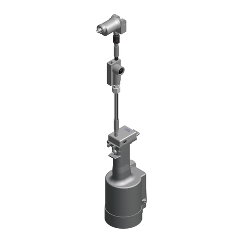
Gage Bilt
Gage Bilt GB722 Original instructions

Astro Pneumatic Tool
Astro Pneumatic Tool PRN2 manual

Emhart Teknologies
Emhart Teknologies POP ProSet 2100 Series Maintenance manual

Gage Bilt
Gage Bilt GB2620A instructions
Degometal
Degometal GO 230 Safety and operating instructions

WERKZEUG
WERKZEUG 44322-WW manual
