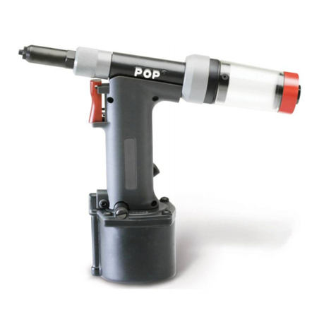
Emhart Teknologies POP ProSet 2100 Series User manual

ProSet2100 Series
Maintenance Manual
Rivet
Tool

Page 2Emhart Teknologies -50 Shelton Technology Center, Shelton CT 06484 -Tel. (203) 924-9341 -Fax (800) 225-5614
Introduction
Introduction . . . . . . . . . . . . . . . . . . . . . . . . . . . . . . . . . . . . . . . . . . . . . . . . . . . . . . . . . . . . . . . . . . .
2
Safety Instructions & Precautions . . . . . . . . . . . . . . . . . . . . . . . . . . . . . . . . . . . . . . . . . . . . . . . .
3
Specifications . . . . . . . . . . . . . . . . . . . . . . . . . . . . . . . . . . . . . . . . . . . . . . . . . . . . . . . . . . . . . . . . .
4
Packaged Accessories
Tool Requirements
Tool Dimensions
Common Nosepieces
Basic Tool Operation . . . . . . . . . . . . . . . . . . . . . . . . . . . . . . . . . . . . . . . . . . . . . . . . . . . . . . . . . . .
6
Front-End Service
Mandrel Collector System (MCS)
Adjusting Low-Flow Vacuum
Cleaning the MCS Filter
Exploded View of Tool . . . . . . . . . . . . . . . . . . . . . . . . . . . . . . . . . . . . . . . . . . . . . . . . . . . . . . . . . .
10
Parts List . . . . . . . . . . . . . . . . . . . . . . . . . . . . . . . . . . . . . . . . . . . . . . . . . . . . . . . . . . . . . . . . . . . . .
12
Tool Cross Section .. . . . . . . . . . . . . . . . . . . . . . . . . . . . . . . . . . . . . . . . . . . . . . . . . . . . . . . . . . . .
14
Hydraulic Oil Charging Procedure . . . . . . . . . . . . . . . . . . . . . . . . . . . . . . . . . . . . . . . . . . . . . . . . .
15
Maintenance Schedule . . . . . . . . . . . . . . . . . . . . . . . . . . . . . . . . . . . . . . . . . . . . . . . . . . . . . . . . . .
16
Safety Data . . . . . . . . . . . . . . . . . . . . . . . . . . . . . . . . . . . . . . . . . . . . . . . . . . . . . . . . . . . . . . . . . . .
17
Troubleshooting . . . . . . . . . . . . . . . . . . . . . . . . . . . . . . . . . . . . . . . . . . . . . . . . . . . . . . . . . . . . . . .
18
EC Declaration of Conformity . . . . . . . . . . . . . . . . . . . . . . . . . . . . . . . . . . . . . . . . . . . . . . . . . . . .
19
Thank you for choosing the Emhart Teknologies’ ProSet™ 2100 Series Rivet Tool.
ProSet™ tools are recommended to be used with genuine POPBrand Rivets.
Models Diameter Rivet Size Nose Housing Diameter
ProSet™ 2100
(P/N: PA203-001)
ProSet™ 2100 MCS
(P/N: PA203-003)
0.953” (24.2 mm) Max.
ProSet™ 2101 *
(P/N: PA203-002)
ProSet™ 2101 MCS *
(P/N: PA203-004)
3/32” to 3/16” (2.4 to 4.8 mm)
0.689” (17.5mm) Max.
Contents
*ProSet™ 2001 models are recommended for rivet break loads of 1,000 lbs. max.

Emhart Teknologies -50 Shelton Technology Center, Shelton CT 06484 -Tel. (203) 924-9341 -Fax (800) 225-5614 Page 3
1. DO NOT use this tool in a manner other than that recommended by Emhart Teknologies.
2. Always wear eye protection. When using the tool both the operator and any person(s) in the
vicinity are required to wear eye protection to protect against injury.
3. Inspect tool for damage before connecting to air supply.
4. Trained personnel must perform tool repair and/or maintenance at the prescribed intervals
for damage and functionality.
5. Disconnect the air supply when adjusting, servicing or removing any part of the tool.
6. Keep your fingers off of the trigger when connecting the air supply.
7. Keep your fingers away from the front of the tool when connecting the air supply or setting
rivets.
8. DO NOT point the tool at any person(s) or the operator.
9. DO NOT operate tool with nose housing removed.
10. DO NOT operate tool without deflector or MCS options.
11. DO NOT modify the tool in any way. In addition to voiding any applicable warranties,
unauthorized modifications can result in damage to the tool or physical injury to the user.
12. DO NOT look into the tool from the front or the back during use. Rivets or expended
mandrels may be ejected resulting in injury.
13. The operating pressure shall not exceed 100 psi (6.9 bar).
14. DO NOT direct tool exhaust towards anyone.
15. If there is excessive contact with hydraulic fluid or lubricants, care should be taken to wash
thoroughly.
16. Take care to keep hair, fingers and loose clothing away from moving parts of the tool to
avoid entanglement and/or physical injury.
TO INSURE PROPER FUNCTIONING AND SAFE OPERATION READ THIS MANUAL
CAREFULLY BEFORE SETTING UP OR OPERATING THE ProSet™ 2100 SERIES TOOLS
Safety Instructions

Page 4Emhart Teknologies -50 Shelton Technology Center, Shelton CT 06484 -Tel. (203) 924-9341 -Fax (800) 225-5614
Packaged Accessories
Qty Item 2100 2101 Part No.
1ProSet™ Rivet Tool üü
1Operating Instructions üüP449
1Maintenance Manual üüP442
1Nosepiece for 4 size open end rivets üInstalled PRN414
1Nosepiece for 5 size open end rivets üüPRN514
1Nosepiece for 6 size open end rivets Installed üPRN614
1Jaw Pusher -üPRG520-33
1Air Hose Assembly üüPRT5200-220
1Warranty Card üüFG2184
Air supply * 6 scfm (150 l/min) Minimum
Recommended Operating Pressure 72.5-90 PSI (5.0-6.2 Bar) dry, filtered
Maximum Operating Pressure 100 PSI (6.9 Bar) dry, filtered
Hydraulic Oil ** POP®p/n: PRG540-130 [1 qt. (.945 ml)] (Mobil DTE 26)
Jaw Lubricant ** POP®p/n: PRG510-130 [6 oz. (177 ml)]
Seal Lubricant ** Lubriplate®130 AA
*
Note: For best results and long service life, use only a dry filtered air supply.
**
Note: See lubricant safety information.
Lubriplate®is a register mark of Fiske Brothers Refining Company.
ProSet™ 2100 ProSet™ 2101
w/o MCS w/MCS w/o MCS w/MCS
Weight 3.31 lbs. (1.5 kg) 3.70 lbs. (1.68 kg) 3.13 lbs. (1.4 kg) 3.50 lbs. (1.59 kg)
Length 11.14” (283.0 mm) 12.32” (312.9 mm) 10.53” (267.5 mm) 11.71” (297.4 mm)
Height 11.07” (281.2 mm) 10.85” (275.6 mm)
Tool stroke .669” (17 mm) .629” (16 mm)
Pulling force * 1900 lbs @ 85 PSI (8452N @ 5.9 bar) 1900 lbs@ 85 PSI (8452N @ 5.9 bar)
Air consumption
per rivet .011 cu. ft.
(.31 liters)/rivet 0 to 2 scfm
adjustable .011 cu. ft.
(.31 liters) / rivet
0 to 2 scfm
adjustable
Tool Requirements
Specifications
*ProSet™ 2001 models are recommended for rivet break loads of 1,000 lbs. max.

Emhart Teknologies -50 Shelton Technology Center, Shelton CT 06484 -Tel. (203) 924-9341 -Fax (800) 225-5614 Page 5
3.45” (87.6 mm)
.953” (24.2 mm)
[.689” (17.5 mm)]
11.07” (281.2 mm)
[10.85” (275.6 mm)]
11.14” (283 mm)
[10.53” (267.5 mm)]
Tool Dimensions
3.8” (96.5 mm)
3.45” (87.6 mm)
11.07” (281.2 mm)
10.85” (275.6 mm)
3.45” (87.6 mm)
11.07” (281.2 mm)
[10.85” (275.6 mm)]
.953” (24.2 mm)
[.689” (17.5 mm)]
2.29” (58.2 mm)
3.8” (96.5 mm)
ProSet™ 2100
&
ProSet™ 2101
Dimensions shown in square brackets [ ]
ProSet™ 2100 MCS
&
ProSet™ 2101 MCS
Dimensions shown in square brackets [ ]
12.32” (312.9 mm)
[11.71” (297.4 mm)]

Page 6Emhart Teknologies -50 Shelton Technology Center, Shelton CT 06484 -Tel. (203) 924-9341 -Fax (800) 225-5614
* Included with the tool.
Before operating the tool check the following:
qInspect tool for damage or leaking oil.
•Do not use tool if damaged or leaking oil.
qCheck to see that correct nosepiece is installed into the nose housing.
•Tighten nosepieces to 60-65 in-lbs. of torque.
qBe sure that the nose housing nut (9) is tight.
•Hand tighten only.
qConnect tool to air supply.
•See air supply requirements (page 4).
qTurn on MCS by rotating switch-ring to one of the three ‘ON’ positions.
•MCS style only.
qAdjust low-flow vacuum setting if necessary.
•See “Adjusting low-flow vacuum” (page 8).
qInsert rivet into nosepiece.
qPosition rivet in work piece.
qPull trigger to set rivet.
•When turned on, the MCS vacuum will automatically switch to high-flow mode and
transfer the mandrel into the collector bottle.
qRelease trigger.
•MCS low-flow will begin to time out. (Approx. 5 to 18seconds).
Closed End T-Rivet HR Rivets
Rivet Diameter Open End
Steel
Mandrel
Aluminum
Mandrel Aluminum
Body
Steel
Body
3/32” (2.4 mm) PRN314 -----
1/8” (3.2 mm) or
7/64” (2.8 mm) PRN414*PRN424 PRN434 -PRN414 PRN4H
5/32” (4.0 mm) PRN514*PRN524 PRN534 -PRN514 PRN5H
3/16” (4.8 mm) PRN614*PRN624 PRN634 PRN625 PRN614 -
Common Nosepieces
Basic Tool Operation

Emhart Teknologies -50 Shelton Technology Center, Shelton CT 06484 -Tel. (203) 924-9341 -Fax (800) 225-5614 Page 7
1. REMOVE NOSE HOUSING:
Remove Nose Housing Assembly by grasping the
Nose Housing Nut by hand and rotate the entire
assembly counterclockwise until the threads are
fully disengaged. Tools are not required, however,
flats are provided as back-up.
Slide Nose Housing Assembly off the tool.
2. REMOVE JAW GUIDE TO ACCESS JAWS
INTERNAL PARTS:
Pull back the Collar to disengage the Collar teeth
from the Jaw Guide teeth.
Once the teeth are disengaged unscrew the Jaw
Guide from the Pulling Head Adaptor.
Remove jaws, jaw pusher, and jaw pusher spring for
servicing. Tools are not required.
3. CLEAN PARTS:
Clean jaws, jaw guide, jaw pusher, spring and
thread area of the pulling head adaptor. Also be
sure to clean the inside of the Nose Housing
Assembly. A long narrow wire may be needed to
loosen debris at the inside-front surface.
4. REASSEMBLY OF INTERNAL PARTS AND JAW
GUIDE:
Apply Lubriplate to jaws and to conical area of the jaw
guide and Jaw Pusher.Place the Jaws and Jaw
Pusher into the Jaw Guide and slide the Jaw Pusher
Spring into the Pulling Head Adaptor.
Apply a slight amount of Lubriplate®130 AA to the
Pulling Head Adaptor threads and Collar teeth. Screw
the Jaw Guide onto the Pulling Head Adaptor until the
teeth on the Collar causes the Jaw Guide to stop
rotating.
Do not pull the collar back and fully tighten jaw
guide onto the pulling head adaptor.
Apply jaw lube to the jaw area by submerging the
assembled jaw guide into jaw lube about 1 in.(25mm).
Make sure the MCS unit is turned off.
5. REINSTALL NOSE HOUSING ASSEMBLY:
Slide the Nose Housing Assembly over the Pulling
Head Adaptor. Hand tighten the Nose Housing Nut
onto the Adaptor so that it squeezes snuggly against
the Nose Housing Seal.
Do not use a wrench to tighten the nose housing
onto the tool. The wrench flats are only to assist
removal of the nose housing when necessary.
Check to make sure that there is sufficient squeeze on
the Nose Housing Seal. There may be a loss of
vacuum if the Nose Housing Seal is not fully engaged.
Note: Turn off MCS unit while servicing tool to avoid sucking any oils or other fluids into the MCS unit.
Front End Service
For optimal tool performance, Front End maintenance should be performed regularly per the “Preventative Maintenance
Schedule”.
Nose Housi
ng
Assembly
Nose Housing Nut
Adapter
To remove
ONLY
Collar
Jaw
Guide
Jaw Guide
Tooth
Collar teeth
(12 teeth)

Page 8Emhart Teknologies -50 Shelton Technology Center, Shelton CT 06484 -Tel. (203) 924-9341 -Fax (800) 225-5614
Mandrel Collection System (MCS)
For ProSet™ 2100MCS & ProSet™ 2101MCS.
The MCS suction on the ProSet™ model tools is switched ON and OFF by turning the red Switch Ring (21) to
one of the three ON positions.
The MCS features an automatic timer and switch that reduces air flow to a Low-Flow mode if the tool is left idle.
Air Flow Modes
With the Switch Ring in the ON position air will flow through the MCS system. If the trigger has not been pressed
the air flow will be in the Low-Flow mode. Pressing the trigger will activate the Full-Flow mode for 15 –20
seconds. After 15 –20 seconds, if the trigger has not been pressed again the toolwill automatically return to the
Low-Flow mode.
1. Remove Collector Bottle (22) from tool.
2. Remove Filter Cover Assembly (43).
3. Remove Filter (24). (Optional)
4. Connect tool to air supply.
5. Turn on MCS unit by rotating the Switch Ring (21) to one of the three on positions.
•Activate Trigger (5) while rotating Switch Ring (21) to on position.
6. Using a small screwdriver rotate Low-flow adjustment screw.
•Clockwise -reduce vacuum in low-flow mode.If screw is fully in, there won’t be vacuum during the low-
flow mode.
•Counter clockwise –increase vacuum in low-flow mode. If screw is fully back, vacuum during the low-
flow mode will continue at full flow.
DO NOT attempt to remove Low Flow Adjustment Screw. A flange on the blind side prevents removal
and the assembly will be damaged if removal is attempted.
7. Replace filter (24).
•Be sure that filter does not cover both Low-flow adjustment and vacuum holes.
8. Replace Filter Cover Assembly (43).
9. Replace Collector Bottle (22).
Adjusting Low-Flow Vacuum

Emhart Teknologies -50 Shelton Technology Center, Shelton CT 06484 -Tel. (203) 924-9341 -Fax (800) 225-5614 Page 9
Cleaning the MCS Filter
For optimal performance, the MCS filter should be cleaned at regular intervals per the “Preventative
Maintenance Schedule”.
Note: Turn off MCS unit AND UNPLUG AIR SUPPLY while servicing MCS to avoid INJURY.
1. CLEAN THE MANDREL COLLECTION UNIT:
•Remove and empty the Collector Bottle (22)
by unscrewing counterclockwise.
•Remove the Filter Cover Assembly (43) by
taking hold of the center stem and pulling
the assembly out.
•Remove the Filter (24).
•Remove debris from the back of the MCS
taking care not to let debris fall into the
piston shaft area.
2. RE-ASSEMBLE THE MANDREL
COLLECTION UNIT:
•Place the Filter (24) back into the MCS unit
ensuring that the oval slot in the filter
exposes the two holes in the back of the
MCS.
•Insert the Filter Cover Assembly (43) into
the recess in the back of the unit, O-rings
first.
•Screw on the Collector Bottle (22) hand-tight
so that the O-ring (33) seal squeezes tightly
against the back of the MCS unit.
Filter Cover Assembly (43)
Filter (24)
Low-flow adjustment screw
(use small screwdriver to adjust)
Switch Ring (21)
Vacuum hole
Collector Bottle (22)
w/ O-Ring (33)

Page 10 Emhart Teknologies -50 Shelton Technology Center, Shelton CT 06484 -Tel. (203) 924-9341 -Fax (800) 225-5614
REDUCED DIAMETER OPTION –ProSet™ 2101
FULL DIAMETER OPTION -ProSet™ 2100

Emhart Teknologies -50 Shelton Technology Center, Shelton CT 06484 -Tel. (203) 924-9341 -Fax (800) 225-5614 Page 11
PRT OPTION
MCS OPTION

Page 12 Emhart Teknologies -50 Shelton Technology Center, Shelton CT 06484 -Tel. (203) 924-9341 -Fax (800) 225-5614
ITEM
Part No. DESCRIPTION
ProSet™ 2100
ProSet™ 2101
ProSet™ 2100
MCS
ProSet™ 2101
MCS
113300 JAW 3-STYLE 3-3-
22001-8549-002 O-RING --11
3DP203-011 SEAL SLEEVE 1111
4DP203-031 HANDLE 1111
5DP203-032 TRIGGER 1111
6DP203-037 END CAP -POP OFF STYLE 11--
7DP203-086 HYDRAULIC PISTON 1111
8DP203-090 NOSE HOUSING –FD 2100 1-1-
9DP203-091 NOSE HOUSING NUT 1111
10 DP203-096 NOSE HOUSING –RD 2101 -1-1
11 DP203-120 CLAMP –LEFT 1111
12 DP203-121 CLAMP –RIGHT 1111
13 DP203-172 JAW GUIDE –RD 2101 -1-1
14 DP203-181 JAW GUIDE –FD 2100 1-1-
15 DP203-191 ADAPTOR 1111
16 DP203-210 ORIFICE –MCS --11
17 DP203-236 BOTTOM HOUSING -MCS --11
18 DP203-245 MCS VALVE STEM --11
19 DP203-250 MCS VALVE STEM SEAL --11
20 DP203-260 TOP HOUSING --11
21 DP203-261 SWITCH RING, MCS --11
22 DP203-263 COLLECTOR BOTTLE, MCS --11
23 DP203-265 LEAK FILTER --11
24 DP203-272 MCS FILTER --11
25 DP203-276 MCS MUFFLER --11
26 DP203-287 VALVE STEM RETAINING BUSHING --11
27 DP900-005 O-RING –ADAPTOR 1111
28 DP900-006 O-RING -COLLAR FD 2100 1-1-
29 DP900-007 O-RING -COLLAR RD 2101 -1-1
30 DP900-008 O-RING -MH2BH --11
31 DP900-009 O-RING -SWITCH RING --11
32 DP900-010 O-RING -FILTER COVER--22
33 DP900-011 O-RING -COLLECTOR BOTTLE --11
34 DP903-001 SCREW -FHSCS 6-32 X 0.500 --33
35 DP904-001 SET SCREW -5/16-18 X 5/32 HOLLOW --11
36 DP906-002 SCREW -4-40 X 3/16 BHCS --11
37 DP907-001 SCREW -6-32 X 1 1/4 SHCS --33
38 DP908-001 SEALING WASHER (2 PC. ASSEMBLY) --11
39 DP909-001 #3 FLAT WASHER -ORIFICE --11
40 FA203-194 PULLING HEAD ADAPTOR ASSEMBLY -2100 1-1-
41 FA203-200 PULLING HEAD ADAPTOR ASSEMBLY -2101 -1-1
42 FA203-277 MIDDLE HOUSING ASSEMBLY --11
43 FA203-281 FILTER COVER ASSEMBLY --11
44 MCS500-22 O-RING –TRANSDUCER --22
45 MCS5200-13 O-RING --11
46 MCS5200-18 O-RING --11
47 MCS5200-19 RETAINER –TRANSDUCER --11
48 MCS5200-20 TRANSDUCER (ASSEMBLY) --11
49 MCS5200-21 O-RING --33
50 MCS5200-3SPRING -VALVE STEM --11
51 MCS5200-7VALVE GUIDE --11
52 PRG402-8A JAW -2-2
53 PRG510-107 O-RING --11
54 PRG510-123 SPRING –JAW PUSHER 1111
Parts List

Emhart Teknologies -50 Shelton Technology Center, Shelton CT 06484 -Tel. (203) 924-9341 -Fax (800) 225-5614 Page 13
ITEM Part No. DESCRIPTION
ProSet™ 2100
ProSet™ 2101
ProSet™
2100 MCS
ProSet™
2101 MCS
55 PRG510-56 DEFLECTOR 11--
56 PRG520-100 SCREWS -RETAINER PLATE 3333
57 PRG520-101 RETAINING RING -SEAL SLEEVE 1111
58 PRG520-106 O-RING –POT 1111
59 PRG520-45 RESTRICTOR 1111
60 PRG520-47 O-RING -SS WIPER 1111
61 PRG520-49 O-RING –END CAP OUTSIDE 1111
62 PRG520-89 O-RING -SS OUTSIDE 1111
63 PRG540-102 WASHER -FILL SCREW 1111
64 PRG540-117 O-RING –VALVE 4433
65 PRG540-118 O-RING –END CAP INSIDE 1122
66 PRG540-120 LOCK WASHER 3333
67 PRG540-122 FILL SCREW 1111
68 PRG540-4O-RING -NH 1111
69 PRN 414 NOSEPIECE 4-SIZE -1-1
70 PRN 614 NOSEPIECE 6-SIZE 1-1-
71 PRT5200-4JAW PUSHER ASSEMBLY -1-1
72 PRT5200-15 PISTON SEAL (2 PC. ASSEMBLY) 1111
73 PRT5200-19 WASHER –SS 1111
74 PRT5200-20 RETAINING RING -SS 1111
75 PRT5200-220 AIR LINE ASSEMBLY (COMPLETE) 1111
76 PRT5200-26 INTENSIFIER ASSEMBLY 1111
77 PRT5200-28 SEAL -AIR PISTON 1111
78 PRT5200-29 INTENSIFIER CHAMBER 1111
79 PRT5200-30 INTENSIFIER CHAMBER SLEEVE 1111
80 PRT5200-33 SPRING PIN –TRIGGER 1111
81 PRT5200-34 JAW PUSHER –CONICAL 1-1-
82 PRT5200-35 VALVE PLUG 1111
83 PRT5200-37 SCREW -END CAP 33--
84 PRT5200-46 RAM SLEEVE 1111
85 PRT5200-47 RESTRICTOR SEAT 1111
86 PRT5200-48 RETAINER PLATE -RAM SLEEVE 1111
87 PRT5200-50 PRESSURE REGULATOR ASSEMBLY 1111
88 PRT5200-59 O-RING -RAM SLEEVE 1111
89 PRT5200-62 SCREW -CLAMP FRONT 1111
90 PRT5200-63 SCREW -CLAMP BACK 1111
91 PRT5200-8ROD SEAL 1111
92 PRT5200-84 RAM SEAL 1111
93 PRT5300-26 GROMMET 1111
94 PRT5500-113 CLAMP NUT 2222
95 PRT5200-55 AIR VALVE ASSEMBLY 1111
96 PRG540-39 AIR LINE 1111
97 PRG540-40 HOSE FEMALE FITTING 1111
98 PRG540-45 AIRLINE “O“ CLAMP 2222
99 PRT5200-90 AIR LINE FITTING 1111
100 FA203-279 BOTTOM HOUSING ASSEMBLY --11
101 FA203-092 NOSE HOUSING ASSEMBLY -2100 1-1-
102 FA203-097 NOSE HOUSING ASSEMBLY -2101 -1-1
107 FA203-405 COLLECTOR BOTTLE ASSEMBLY --11
108 FA203-402 MANDREL COLLECTION SYSTEM --11
109 FA203-404 NOSE HOUSING NUT ASSEMBLY 1111
110 FA203-406 END CAP ASSEMBLY --11
FD: Denotes “Full Diameter” option 2100.
RD: Denotes “Reduce Diameter” option 2101.
Parts List

Page 14 Emhart Teknologies -50 Shelton Technology Center, Shelton CT 06484 -Tel. (203) 924-9341 -Fax (800) 225-5614
Optional Kits are also available separately.
Part No. Description
FA203-400 ProSet™ 2100 Seal Kit
FA203-401 ProSet™ 2100MCS Seal Kit
FA203-403 Reduced Diameter Front End Kit (2100 to 2101 conversion)
FA203-408 ProSet™ 2100 Adaptor Kit for MCS5000 (remote MCS)
FA203-2102K ReducedDiameter Front End Extension Kit –6” length
FA203-2103K ReducedDiameter Front End Extension Kit –8” length
FA203-2104K Standard Diameter Front End Extension Kit –6” length
FA203-2105K Standard Diameter Front End Extension Kit –8” length
Double balloons indicate 2100 and 2101 equivalents. MCS version shown.
Tool Cross Section

Emhart Teknologies -50 Shelton Technology Center, Shelton CT 06484 -Tel. (203) 924-9341 -Fax (800) 225-5614 Page 15
IMPORTANT.TOOL MUST BE DISCONNECTED FROM THE AIR SUPPLY. USE ONLY APPROVED HYDRAULIC OIL
SPECIFIED IN THIS MANUAL.
1. Disconnect tool from air supply.
2. Remove Nose Housing Assembly (101 or 102).
3. Loosenfill screw (67) together with fill screw washer (63) ¼” turn.
4. Remove clamp screws (89 & 90), clamp nuts (94), right and left
clamps (11 & 12). Note the orientation of Clamp lettering “Made In U.S.A.”.
5. Remove intensifier chamber and sleeve (78 & 79), Remove O-ring (93
& 58). To avoid spilling hydraulic oil,DO NOT remove Intensifier Assembly
(76) at this time.
6. Turn tool upside down as shown in View E1. Slowly withdraw the
intensifier assembly (76), being careful not to scratch or score the
inside of the Ram Sleeve surface (84).
7. Turn the tool right side up over a pan that can capture the hydraulic oil
as it is drained from the tool. The oil will exit the tool out of the Ram
Sleeve (84).
8. Remove or loosen the fill screw Assembly (67 & 63). Allow oil to drain
for a minute or two.
9. Invert the handle, pulling head down (view E1) in a soft jawed vise. Grip the tool gently on the aluminum
casting in the middle of the tool handle grip area.
10. If fill screw (67) and fill screw washer (63) have been removed during dismantling,reinstall these before
proceeding and tighten hand tight (approximately 15 in –lbs).
11. Move the pulling head (40 or 41) to the full forward position. Note:
rotating the pulling head adaptor while moving it will reduce sudden
uncontrolled movement.
12. Fill ram sleeve (84) with hydraulic oil until level with the top of the
ram sleeve.
13. Slowly move the pulling head back, about ½ inch.Then, slowly
return the pulling head to the full forward position. Note: rotating the
pulling head adaptor while moving it will reduce sudden uncontrolled
movement.
14. Refill ram sleeve (84) with hydraulic oil until level with the top of the
ram sleeve. Repeat above procedure a second time.
15. With the pulling head in full forward position, refill ram sleeve, if
needed, with hydraulic fluid until level with the top of the ram sleeve.
16. Slowly move the pulling head back until the oil level in the ram
sleeve drops to approximately ½ inch for top of seal sleeve.
17. Add hydraulic fluid until level with the top of the ram sleeve.
18. Install the intensifier assembly (76) into the ram sleeve. Push in until
it is about 1/3 down.
19. Reposition this assembly to the upright position, as shown on view E2.
20. Let the tool stand for approximately 2 minutes so that any air in the ram sleeve rises to the top.
Hydraulic Oil Charging Procedure
67
63
4
NOTE 23
VIEW “E2”
UPRIGHT POSITION
VIEW “E1”
INVERTED
POSITION
76
84
40 or 41

Page 16 Emhart Teknologies -50 Shelton Technology Center, Shelton CT 06484 -Tel. (203) 924-9341 -Fax (800) 225-5614
Maintenance
21. Move the intensifier (item 76) up approximately ½ inch more. This will force air trapped at the top of the
ram sleeve into the upper bore chamber of the handle, in front of the hydraulic piston.
22. Let the tool stand for approximately 2 minutes so that any air in the upper bore chamber rises towards the
fill screw.
23. Move the intensifier up so that the pulling head is in the full back position. Apply pressure to the bottom of
the air piston and loosen the fill screw until oil seeps by the threads of the fill screw. Continue until the
piston gap setting is .180 (4.6mm). See gap setting.
24. Tighten fill screw to 60-65 in –lbs.
25. Wipe away any excess oil from the handle.
26. Inspect Ram Seal (92) for cuts and defects. Inspect inside
surface of the Ram Sleeve (84) for marks and scratches.
27. Reinstall the intensifier chamber and sleeve (78 & 79)and
O-ring (93 & 58).
28. Install the Clamp assemblies (11, 12, 89, 90 and 94). Be sure
that the orientation of the clamps is correct. Tighten both Clamp
Nuts (94) to 8 –10 in–lbs. NOTE: The orientation of the words
“Made In U.S.A.” on one of the clamps should be the same as the
words “POP” on the Handle (4) and located opposite the air inlet port
of the Handle.
29. Reinstall the Nose Housing Assembly (101 / 102).
Preventative Maintenance Schedule
Item Action Frequency
Clean and lube Front End
of tool See “Front End Service” 1 x per day or
5,000 rivet settings.
Inspect jaws Look for broken jaws and
damage or wear on jaw
gripping teeth.
During Front End service.
When jaws slip on mandrel.
Empty Collector Bottle
When the quantity of stored spent
mandrels begin to interfere with
mandrels entering the collector bottle.
(Storage quantity depends on rivet size
and application).
Clean MCS Filter Once a day or when MCS vacuum will
not pull rivet into collector bottle.
MCS Collector Unit
Clean MCS Muffler 2 months or
250,000 rivet settings.
* Note: Only use Emhart specified greases and lubricants
.180 GAP SETTING.
NOTE
23
GAP SETTING

Emhart Teknologies -50 Shelton Technology Center, Shelton CT 06484 -Tel. (203) 924-9341 -Fax (800) 225-5614 Page 17
LUBRIPLATE®130-AA
Manufactured by:
Fiske Brothers Refining Co.
Phone: (419) 691-2491
First Aid:
SKIN:
Remove any contaminated clothing
and wash with soap and warm
water. If injected by high pressure
under skin, regardless of the
appearance of its size, contact a
physician IMMEDIATELY. Delay
may cause loss of affected part of
body.
INGESTION:
Call a physician immediately. Do
not induce vomiting.
EYES:
Flush with clear water for 15
minutes or until irritation subsides.
If irritation persists, consult a
physician.
Fire:
FLASH POINT: COC-400°F
Cool exposed containers with water.
Use foam, dry chemical, carbon
dioxide or water spray.
Environment:
WASTE DISPOSAL:
Assure conformity with applicable
disposal regulations. Dispose of
absorbed material at an approved
waste disposal facility or site.
SPILLAGE:
Scrape up grease, wash remainder
with suitable petroleum solvent or
add absorbent.
Handling/ Storage:
Keep containers closed when not in
use. Do not handle or store near
heat, sparks, flame or strong
oxidants.
JAW LUBE (P/N: PRG510-130)
Distributed By:
Emhart Teknologies
Phone: (203) 924-9341
First Aid:
SKIN:
Wash with soap and water until no
odor remains. If redness or swelling
develops, obtain medical
assistance. Wash cloths before
reuse.
INGESTION:
Do not induce vomiting! Do not give
liquids! Obtain emergency medical
attention. Small amounts that
accidentally enter mouth should be
rinsed out until taste of it is gone.
EYES:
Flush with water.
Fire:
FLASH POINT: Greater than 200°F
Can be made to burn. Use water
spray, regular foam, dry chemical or
carbon dioxide.
Environment:
WASTE DISPOSAL:
Do not flush to drain or storm sewer.
Contract authorized disposal
service.
SPILLAGE:
Contain Spill. Absorb onto inert
material. Shovel, sweep or vacuum
spill.
Handling/ Storage:
NFPA Class IIIB Storage. Avoid
prolonged breathing of mist or
vapor. Avoid prolonged or repeated
contact with skin. Avoid contact
with eyes. Wash thoroughly after
handling.
MOBIL DTE 26 (P/N: PRG540-130)
Distributed By:
Emhart Teknologies
Phone: (203) 924-9341
Manufactured By:
ExxonMobil Corporation
Emergency Phone: (609) 737-4411
MSDS Fax on Demand:
(613) 228-1467 MSDS # 602649-00
First Aid:
SKIN:
Remove contaminated clothing and
shoes and wipe excess from skin.
Flush skin with water, then wash
with soap and water. If irritation
occurs, get medical attention. Do
not reuse clothing until cleaned.
INGESTION:
Do not induce vomiting. In general,
no treatment is necessary unless
large quantities of product are
ingested. However, get medical
attention.
EYES:
Flush with water. If irritation occurs,
get medical attention.
Fire:
FLASH POINT: 390 °F/198.9 °C
Material will float and can be re-
ignited on the surface of water. Use
water fog, ‘alcohol foam’, dry
chemical or carbon dioxide (CO2) to
extinguish flames. Do not use a
direct stream of water.
Environment:
WASTE DISPOSAL:
SPILLAGE:
Soak up residue with an absorbent
such as clay, sand or other suitable
material. Place in a non-leaking
container and seal tightly for proper
disposal.
Handling:
Wash with soap and water before
eating, drinking, smoking, applying
cosmetics or using toilet. Properly
dispose of leather articles such as
shoes or belts that cannot be
decontaminated. Use in a well
ventilated area.
Storage:
Store in a cool, dry place with
adequate ventilation. Keep away
from open flames and high
temperatures.
Please refer to the actual MSDS for complete safety and handling
information. These can be obtained from the point of purchase.
Safety Data

Page 18 Emhart Teknologies -50 Shelton Technology Center, Shelton CT 06484 -Tel. (203) 924-9341 -Fax (800) 225-5614
Symptom Probable Cause Remedy
TOOL FAILS TO OPERATE
Tool not connected to air supply.
Insufficient air pressure.
Air pressure too high.
Tool low on hydraulic fluid.
Connect to recommended air supply source.
Adjust air supply pressure.
Adjust air supply pressure.
Service tool by qualified service personnel.
TOOL NOT RETURNING Insufficient air pressure. Adjust air supply pressure.
TOOL LOSING STROKE Tool low on hydraulic fluid. Service tool by qualified service personnel.
JAWS SLIPPING ON MANDRELS Jaws dirty or need lubrication.
Jaws worn.
Clean and lube jaws.
Replace jaws.
JAWS FAIL TO OPEN
Insufficient air pressure.
Nose housing loose.
Excess hydraulic oil in tool.
Adjust air supply pressure.
Tighten nose housing.
Service tool by qualified service personnel.
MANDREL STICKING IN JAWS Jaws dirty or need lubrication. Clean and lube jaws.
RIVET FAILS TO INSERT INTO
NOSEPIECE Incorrect nosepiece.
Shear ring stuck in hole of nosepiece.
Install correct nosepiece.
Remove shear ring.
RIVET MANDREL DOES NOT
BREAK
Rivet not fully set.
Mandrel break load requirement too high.
Insufficient air pressure.
Repeat stroke required, or change rivet.
Upgrade tool.
Adjust air supply pressure.
MCS NOT WORKING
Tool not connected to air supply.
MCS switch ring in off position.
Collector bottle not tight or missing.
Collector bottle seal damaged or missing.
Low-flow adjusted to off position.
Mandrel path blocked.
Connect to recommended air supply source.
Rotate MCS switch ring to “ON” position.
Check collector bottle.
Replace seal.
Adjust low-flow valve. Activate trigger to check.
Clear mandrel path.
LOW VACUUM
Collector bottle not tight.
Dirty filter.
Collector bottle seal damaged or missing.
Insufficient air pressure.
Check collector bottle.
Clean or change filter.
Replace seal.
Adjust air supply pressure.
Troubleshooting

Emhart Teknologies -50 Shelton Technology Center, Shelton CT 06484 -Tel. (203) 924-9341 -Fax (800) 225-5614 Page 19
We, Emhart Teknologies
Tucker Fasteners Limited
Birmingham B42 1BP
United Kingdom.
Declare that:
ProSet2100/MCS
ProSet2101/MCS
Conforms to the following standards:
EN 292 part 1 and part 2 ISO prEN 15744
ISO 3744 EN 28662 -1
ISO prEN 792 part 1 EN 12096
EN ISO 4871
Following the provisions of the Machine Directive 98/37/EEC which replaces Directive 89/392/EEC and its
amending Directives 91/368/EEC, 93/44/EEC and 93/68/EEC.
Signed:____________________________________
Eymard Chitty, Vice President, R&D
Birmingham
1st. November 2003
EC Declaration of Conformity

THE AMERICAS
United States
50 Shelton Technology Center
P.O. Box 859
Shelton, CT 06484 USA
Tel. 203-924-9341
Fax. 800-225-5614
Canada
9870 boul. du Golf
Anjou, Quebec H1J 2Y7
Canada
Tel. 514-351-0330
Fax. 514-351-0458
Brazil
Rua Ricardo Cavatton, 226 LAPA
CEP 05038-110 Sao Paulo, SP
Brazil
Tel. +55-11-3871-6460
Fax +55-11-3611-3508
México
Bosque de Radiatas No 42
Bosques de las Lomas
05120 México, D.F.
Tel. +52-555-326-7100
Fax. +52-555-326-7141
EUROPE
Denmark
Farverland 1B
DK-2600 Glostrup, Denmark
Tel. +45-4484-1100
Fax. +45-4484-6212
Finland
Hyttmästargränden 4,
FlN-02780 Esbo, Finland
Tel. +358 9 8190060
Fax. +358 9 812428
France
ZA des Petits Carreaux
Bâtiment Haute Technologie No 8 Lot
B
2 bis, Avenue des Coquelicots
94385 Bonneuil-Sur-Marne
France
Tel. 33-1-5671-2424
Fax. 33-1-5671-2434
Norway
Postboks 153, Leirdal
1009 Oslo, Norway
Tel. +47 2290-9990
Fax. +47 2290-9980
Spain
Carretera M-300 Km 29,700
28802 Alcalá de Henares
Madrid, Spain
Tel. 34-91-887-1470
Fax. 34-91-882-3602
Sweden
Skjutbanevägen 6
SE-701 44 Örebro, Sweden
Tel. +46 19 2058000
Fax. +46 19 260038
United Kingdom
177 Walsall Road
Perry Barr
Birmingham, B42 1BP
United Kingdom
Tel. +44 (0) 121 356-4811
Fax. +44 (0) 121 356-1598
ASIA PACIFIC
Japan
Shuwa Kioicho Park Building 302
3-6 Kioicho, Chiyoda-Ku
Tokyo, 102-0094, Japan
Tel. 81-03-3265-7291
Fax. 81-03-3265-7298
Korea
Rm 609, Seorin Bldg.
45-15 Yeoido-Dong
Yeongdeungpo-Ku
Seoul, 150-891, R.O. Korea
Tel. 82-2-783-9226
Fax. 82-2-783-9228
P.R.China
488 Jiatang Road
Jiading District
Shanghai 201807
People’s Republic of China
Tel. 86-21-5954-8626
Fax. 86-21-5954-8775
Visit our website at
http://www.emhart.com
©2005 Emhart Industries, Inc. Form No. P442 Rev. 3(07/05)
This manual suits for next models
7
Table of contents
Other Emhart Teknologies Rivet Tools manuals
Popular Rivet Tools manuals by other brands

TKR Group
TKR Group VAS 6790/1 Original instructions
FAR
FAR RAC 230 Original instruction

Hilti
Hilti RT 6-A22 Original operating instructions

Gesipa
Gesipa AccuBird Pro Operating manual with spare parts list

Würth
Würth HES 510-OZS operating instructions

Gesipa
Gesipa AccuBird Operating manual with spare parts list
